Skipper DL2 User manual

DL2
Dual Axis Doppler Speed Log System (SOG+STW)
Installation Manual
SKIPPER Electronics AS Telephone: +47 23 30 22 70
Enebakkveien 150 Telefax: +47 23 30 22 71
P. O. Box 151, Manglerud E-mail: support@skipper.no
0612 Oslo, Norway Co. reg. no: NO-965378847-MVA
www.skipper.no
Document no: DM-M002-SA
Rev: 1723A
Date: 2018-05-28
(for softwares up to 1.0.14 &1.1.0)
BRIDGE
FORE PEAK
115-230VAC
/ 24VDC
DL21SG-SA
DL21 sensor
w/40m cable
in Sea valve
SB-100-SB
JB21-SA
Junction box
JB70D21-SA
Electronic Unit
Sensor extension cable.
Yard supply.
6 x twisted shielded pairs
Dimension: see DL2 manual Chapter 3.
JB12-SA
Junction box
DL2SG-SA
DL2 sensor
w/40m cable
in Sea valve
SB-100-SB
JB70D2-SA
Electronic Unit
Sensor extension cable.
Yard supply.
3 x twisted shielded pairs
Dimension: see DL2 manual Chapter 3.
CU-M001-SA Operator Unit for DL2
LAN cable. CAT6. Max. 100m
24VDC

Page 2 of 60 2018-05-28
Installation DL2 Doppler Speed Log System
INSTALLATION MANUAL
DL2 DUAL AXIS DOPPLER SPEED LOG SYSTEM
Copying of this document, and giving it to others and the use
or communication of contents thereof, are forbidden without
express authority. Offenders are liable to the payment of dam-
ages.
Sin nuestra expresa autorización, queda terminantemente
prohibida la reproducción total o parcial de este documento,
asì como su uso indebido y/o su exhibición o comunicación
a terceros. De los infractores se exigirá el correspondiente
resarcimiento de daños y perjuicios.
Weitergabe sowie vervielfältigung dieser unterlage, verwertung und mitteilung ihres
Inhaltes nicht gestattet, soweit nicht ausdrücklich zugestanden. Zuwiderhandlungen
verpichten zu schadenersatz.
Toute communication ou reproduction de ce document, toute Exploitation ou
communication de ou son contenu sont interdites, sauf autorisation expresse.
Tout manquement à cette règle est illicite et expose son auteur au versement de
dommeges et intèrèts.

2018-05-28 Page 3 of 60
Installation DL2 Doppler Speed Log System
COMMUNICATING WITH US
If you need more information, support or other assistance from us, do not hesitate to contact us:
SKIPPER Electronics AS
P. O. Box 151, Manglerud
NO-0612 Oslo
Norway
Phone: (+47) 23 30 22 70, Fax: (+47) 23 30 22 71
E-mail: support@skipper.no
SOFTWARE UPDATES AND TECHNICAL SUPPORT
Find us on the internet: www.skipper.no
YOUR FEEDBACK IS APPRECIATED
If you nd errors, misspellings or poorly explained sections in this document, please do not hesitate
to contact us at:
support@skipper.no

Page 4 of 60 2018-05-28
Installation DL2 Doppler Speed Log System
CONTENTS
TERMINOLOGY......................................................................................................................... 5
Terms used in this manual................................................................................................................................... 5
CHAPTER 1: GETTING STARTED ........................................................................................... 7
Overview DL2...................................................................................................................................................... 7
Optional items DL2.............................................................................................................................................. 8
Items Not supplied by SKIPPER ......................................................................................................................... 9
Power supply requirements................................................................................................................................. 9
CHAPTER 2: HARDWARE MOUNTING ................................................................................... 10
Placement of the Operator unit ........................................................................................................................... 10
Placement of the electronic unit .......................................................................................................................... 11
Placement of the electronic unit IP22 approved.................................................................................................. 11
Placement of JB12 Junction box ......................................................................................................................... 11
Placement of repeaters ....................................................................................................................................... 11
Placement of the sea valve ................................................................................................................................. 12
Placement of the Sensor in sea valve ................................................................................................................. 13
CHAPTER 3: WIRING................................................................................................................ 16
Clamping the cables............................................................................................................................................ 16
CU-M001-SA Operator unit wiring....................................................................................................................... 17
JB70D2-SA Electronic Unit Wiring ...................................................................................................................... 18
Connectors supplied with JB70D2 ...................................................................................................................... 19
SENSOR CONNECTION J3 ............................................................................................................................... 20
NMEA CONNECTION J1 .................................................................................................................................... 21
AUX/Alarm CONNECTION J2............................................................................................................................. 22
Additional NMEA, Aux and analog Out................................................................................................................ 22
Yard supplied extension cable from sensor to JB70 Electronic unit.................................................................... 23
The junction box (JB12)/splice ............................................................................................................................ 23
CHAPTER 4: SETUP PROCEDURE......................................................................................... 26
CONFIG .............................................................................................................................................................. 27
CU-M001 setup ................................................................................................................................................... 28
JB70D2 setup...................................................................................................................................................... 29
DL2 setup ............................................................................................................................................................ 30
Reset.............................................................................................................................................................. 33
Software options............................................................................................................................................. 34
Communications setup (NMEA/UDP) ................................................................................................................. 36
NMEA............................................................................................................................................................. 36
LAN UDP........................................................................................................................................................ 36
NMEA sentences received ............................................................................................................................. 38
NMEA sentences transmitted ........................................................................................................................ 39
Alarm/Alert setup................................................................................................................................................. 40
Setup AUX........................................................................................................................................................... 44
System Diagnostics ............................................................................................................................................ 45
Available options in the diagnostic page ............................................................................................................. 45
Error messages ................................................................................................................................................... 45
Saving and locking ............................................................................................................................................. 46
Status LEDs ....................................................................................................................................................... 46
Hardware options ................................................................................................................................................ 47
CHAPTER 6: SOLVING PROBLEMS........................................................................................ 48
Software upgrade ................................................................................................................................................ 48
APPENDIX 1: INSTALLATION DRAWINGS ............................................................................. 49
APPENDIX 2: DATA SHEETS ................................................................................................... 55
APPENDIX 3: MULTI EXTENSION PCB................................................................................... 58
APPENDIX 4: CONNECTING 2 SYSTEMS .............................................................................. 59
APPENDIX 4: COMMISIONING CHECKLIST........................................................................... 60

2018-05-28 Page 5 of 60
Installation DL2 Doppler Speed Log System
TERMINOLOGY
Terms used in This manual
_________________________________________________________
Units
Unless otherwise stated, all values shown on the display are as follows:
Speed Knots
Distance (Vessel) Nautical miles
Depth Meters
Tilt ° Degrees
Temperature ° Centigrade
Rotation Degrees per minute
Heading Degrees
Abbreviations
In addition, the following symbols are used
WT Water track
BT Bottom track
STW Speed through water
SOG Speed over ground
Trip Text for trip/total
ECDIS Electronic Chart Display and Information System
INS Inertial Navigation System
VDR Voyage Data Recorder
ROT Rotation from Gyro
GYRO Gyroscopic heading / rotation sensor
HDG Heading
DL2 2 Axis Doppler Log (with speed over bottom and Speed through water)
DL1 1 Axis speed through water sensor (part of DL21 system)
DL21 A system with combined DL1 and DL2 in the same housings
UDP User Datagram Protocol.
SFI System function Id
LAN Local Area Network
Symbols
In addition, the following symbols are used
Indicating that the information presented is partly from the GPS input, and therefore not
from this sensor. (Outputs may show invalid data in this mode)
Symbolising that the data presented is longitudinal (forward or backwards)
Symbolising the data is transversal (port or starboard)

Page 6 of 60 2018-05-28
Installation DL2 Doppler Speed Log System
Alarm active. Unacknowledged (ashing)
Alarm active. Silenced (ashing)
Alarm active. Acknowledged
Alarm active - Responsibility transferred alarm
Alarm rectied - Unacknowledged
Simulator mode - The system is using a simulator to generate the speed and depth
Option - Mute mode. The system has a sync option activated and is currently being
muted (No acoustics)
Symbolising the resultant speed direction

2018-05-28 Page 7 of 60
Installation DL2 Doppler Speed Log System
CHAPTER 1: GETTING STARTED
Overview dl2
The DL2 dual axis Doppler speed log is a Navigational Doppler Speed log system that measures
speed in two axis (longitudinal and transversal) through the water and over the sea bed. The system
requires no external inputs, however adding inputs from other navigational systems enhances the
functionality and allows comprehensive quality control of the data.
The system fullls all class and type regulations based on MED B (wheelmark) and is manufactured
in Norway under stringent production controls.
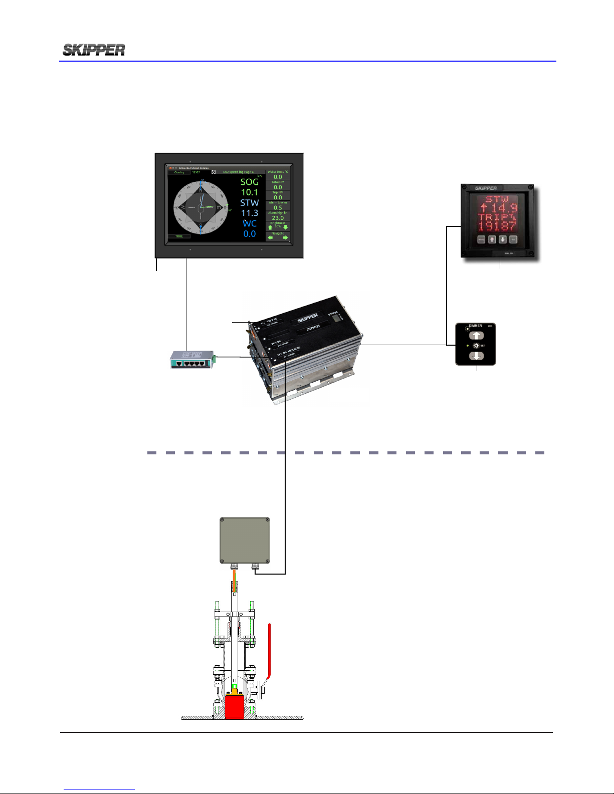
The system comprises of 5 units;
1. The Operator unit – CU-M001-SA
The system is to be tted with a touch
display panel where full setup and
operation can be performed.
2. The electronic unit – JB70D2-SA
This unit comprises of a processor
and a power supply. It is a compact
single euro cabinet. It enables the
user to interface to both modern and
older navigation systems with all the
expected connectivity. The unit has a
built-in web server, allowing the system
to be fully integrated into existing
navigation systems (extra approvals
may apply).
3. Junction box JB12-SA. To connect
sensor cable to yard supplied extension
cable.
4. The sensor – The sensor (DL2SG-
SA) contains acoustic elements and
a fully programmable transceiver unit,
allowing the system to adapt itself
to the conditions and requirements.
In addition the sensor contains a
temperature sensor and tilt sensors.
5. Sea valve. The sensor may be installed
into a sea valve for single bottom hull
(SB-100-XX) or sea valve for double
bottom hull (DB-100-XX).
BRIDGE
FORE PEAK
115-230VAC
/ 24VDC
DL21SG-SA
DL21 sensor
w/40m cable
in Sea valve
SB-100-SB
JB21-SA
Junction box
JB70D21-SA
Electronic Unit
Sensor extension cable.
Yard supply.
6 x twisted shielded pairs
Dimension: see DL2 manual Chapter 3.
JB12-SA
Junction box
DL2SG-SA
DL2 sensor
w/40m cable
in Sea valve
SB-100-SB
JB70D2-SA
Electronic Unit
Sensor extension cable.
Yard supply.
3 x twisted shielded pairs
Dimension: see DL2 manual Chapter 3.
CU-M001-SA Operator Unit for DL2
LAN cable. CAT6. Max. 100m
24VDC
Page 8 of 60 2018-05-28
Installation DL2 Doppler Speed Log System
OpTiOnal iTems dl2
The following optional items are SKIPPER supplied:
- Speed Repeater CD401MR-SB
- External NMEA dimmer IR31DIM-SA
- LAN switch
BRIDGE
FORE PEAK
115-230VAC
/ 24VDC
CD401MR-SB
Repeater NMEA
IR31DIM-SA
External
dimmer
NMEA
24VDC
24VDC
I/O DL2
DL21SG-SA
DL21 sensor
w/40m cable
in Sea valve
SB-100-SB
JB21-SA
Junction box
JB70D21-SA
Electronic Unit
Sensor extension cable.
Yard supply.
6 x twisted shielded pairs
Dimension: see DL2 manual Chapter 3.
JB12-SA
Junction box
DL2SG-SA
DL2 sensor
w/40m cable
in Sea valve
SB-100-SB
JB70D2-SA
Electronic Unit
Sensor extension cable.
Yard supply.
3 x twisted shielded pairs
Dimension: see DL2 manual Chapter 3.
CU-M001-SA Operator Unit for DL2
LAN cable. CAT6. Max. 100m
24VDC
LAN switch
(option)

2018-05-28 Page 9 of 60
Installation DL2 Doppler Speed Log System
iTems nOT supplied by sKipper
The following items are not SKIPPER supplied:
- LAN cable (minimum CAT6) from Operator unit to Electronic unit.
- The sensor is manufactured with a 40m cable. The cable may be cut or extended. Extension cable
is minimum CAT7 type. See chapter 3 for lengths and dimensions.
pOwer supply requiremenTs
The following power supplies are required
- CU-M001-SA. Operator Unit. 24VDC. Max 10W, Typical 6W.
- JB70D2-SA. Electronic unit: 24VDC and/or 115/230VAC. Max 60W typical 15W.
There are no power switch on the CU-M001-SA or JB70D2-SA.
The power input should be including a manual circuit breaker.
There are no input fuse on the CU-M001-SA or JB70D2-SA.
The power input should be including a fuse rated for 100% - 200% of max power installed components.
Example: 24V DC to power CU-M001-SA and JB70D2-SA should have a 3A slow blow fuse.
Optional items power supply requirement:
- CD401MR repeater. 24VDC. Max 10W, Typical 6W.
- IR31DIM-SA. External dimmer: 24VDC
- LAN switch: 24VDC

Page 10 of 60 2018-05-28
Installation DL2 Doppler Speed Log System
CHAPTER 2: HARDWARE MOUNTING
placemenT Of The OperaTOr uniT
The operator unit is placed on the bridge.
Some standards require some operations of
the unit to be available from ‘standing position’.
These operations are available from the operator
unit and multi-repeaters if both input and output
are connected.
Dimensional drawings are found in Appendix 1.
Flush mount installation
Wall mount installation

2018-05-28 Page 11 of 60
Installation DL2 Doppler Speed Log System
placemenT Of The elecTrOnic uniT
The electronic unit can be installed on a DIN rail or directly
screwed onto the wall.
All parts of the system are connected to the electronic unit.
There are no buttons (like ON/OFF) in the electronic unit.
Access is only required for service purpose.
Placement is typically in or near the bridge where the
interfaced systems are available, but no nearer than 0.5 m
to the GYRO heading sensor.
placemenT Of The elecTrOnic uniT ip22 apprOved
If IP22 is required for electronic unit then:
- Alternative 1
Horisontal installation. PCB’s vertical. IP22 Drip plate installed.
-Alternative 2
Vertical installation
Alternative 1 Alternative 2
Drip plate
placemenT Of repeaTers
Repeaters are typically installed on the overhead console and/or the bridge wings. These can be
routed using NMEA signals. These require a local +24 V DC supply.
66
31,5
165,5
141
161
70
125
144
6,1 (4x)
Approved by - date
HK 2012.02.09
Designed by - date
1 of 1
JB12 Outline Drawing
Scale
OD-JB12
Revision
X0
Sheet
Edition date
Name
Drwg. no.
CN
Checked by
Material
Eur. projection
Gen. tolerance
1:2
ISO2768m
E
D
Electronics AS
B
A
8
7
6
4
D
C
5
1
2
3
A
B
4
3
2
1
C
F
E
placemenT Of Jb12 JuncTiOn bOx
The junction box JB12 is an option for connecting sensor cable to a yard
supplied extension cable (See chapter 3).
It is placed in a dry place within reach of the 40m sensor cable.

Page 12 of 60 2018-05-28
Installation DL2 Doppler Speed Log System
placemenT Of The sea valve
Mounting instructions for the sea valve is available from the SKIPPER web site in separate manual
depending on the chosen type. When placing the speed log sensor, consider the following moments:
• Free sight to the bottom (it should be possible to draw a cone of +-45 degrees from the
sensor to the bottom).
• The active face of speed sensor must be in parallel to the horizontal line, max offset +-1°.
• Do not mount transducers aft of bow thruster, propeller outlets or aft of other hull
installations (such as outlets, vents or other protruding details) that may create aeration or
turbulence.
• It is necessary to select a part of the hull that is submerged and free from turbulence and
aeration under all load and speed conditions, and to avoid positions where air is trapped in
heavy weather.
• If a at, horizontal section is not available for transducer tting, the shipyard must construct
a suitable bed. Welding seams in this area and forward should be smoothed and rounded
off in order not to create turbulence or aeration and maintain a laminar waterow at all
speed ranges of the vessel.
• Select an area that is acoustically quiet. The system operates at frequencies between 270
kHz and 284 kHz.
There are 2 channels in DL2.
The acoustic signal is sent in
a 30deg angle in forward and starboard
directions.
In addition a tilt sensor is used to
compensate for vessel movement.
FWD
PORT STRB
AFT
DL2
Longitudal speed
channel
DL2
Transversal speed
Channel
A
Bubbles
Sensor installation
A
Bubbles
Side view
Bottom view
Sensor placed
fore
Water relative speed is measured at a depth
between 0.3 and 3 m below transducer.
(DL1)
2 axis Water relative speed is measured at a
depth between 0.3 and 3 m below
transducer. (DL2)
Bottom track is measured down to 150m
depth

2018-05-28 Page 13 of 60
Installation DL2 Doppler Speed Log System
The generally best placement on larger vessels is in the front region of the vessel just behind the
bulbous bow (see g above). This area is generally designed such that the bubbles are pushed to
either side of the bulb, leaving a clear area under the bulb and just behind. The sensor is installed in
a sea valve in order to service the sensor (clean or replace) without docking the vessel.
It is recommended (but not required) to install the sea valve in a dry area, like a bow thruster room.
This will enable easy cable access to junction box and additionally increase the lifetime of the sea
valve.
The sensor DL2 is installed into sea valve
100mm for single bottom SB-100-SB or
double bottom DB-100-SB.
Please see sea valve manual for installation
procedure.
Manuals available as downloads from
www.skipper.no
The sensor includes 40m moulded in cable.
The cable is 11 mm in outer diameter with a
bending radius of 56 mm. The cable can be
cut or extended if required
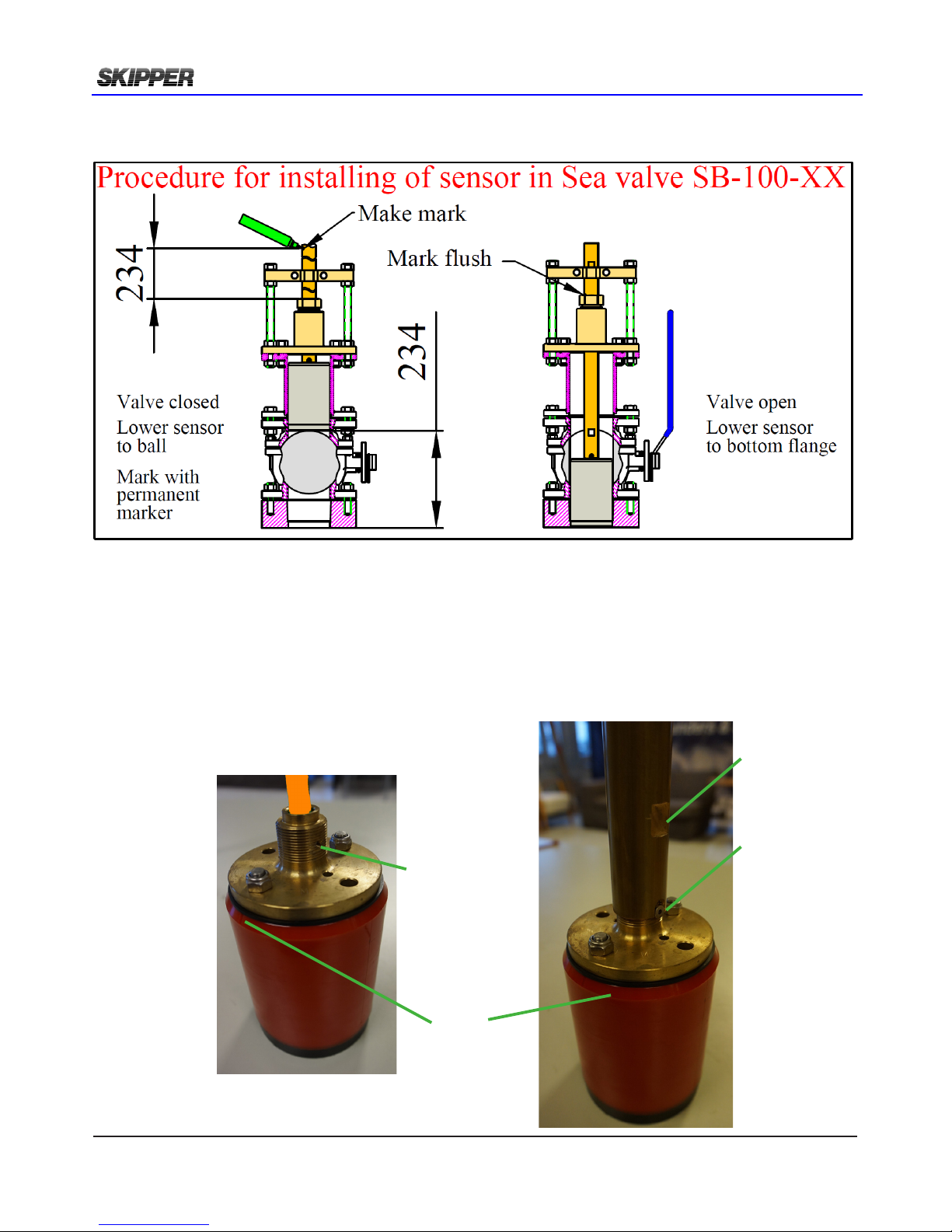
placemenT Of The sensOr in sea valve
NOTE
During physical installation of sensor into sea valve please make special care of the following points:
• Sensor to be lowered completly into bottom ange making sensor head ush with outer hull.
• Sensor forward direction to be aligned +/-10deg. (Fine adjust by software in calibration page)
• Clamping unit nuts and nut M50 to be tighten to secure sensor position.
Page 14 of 60 2018-05-28
Installation DL2 Doppler Speed Log System
Sensor forward direction.
It is important to align sensor forward direction.
Pictures showing forward direction alignment in sea valve SB-100-SB.
Sensor lowered ush with outer hull.
Pictures showing lowering procedure in sea valve SB-100-SB.
Threaded hole
Port side
Forward
position mark
in moulding
Screw M4
In threaded
hole
Port side
Flat area
Port side
2018-05-28 Page 15 of 60
Installation DL2 Doppler Speed Log System
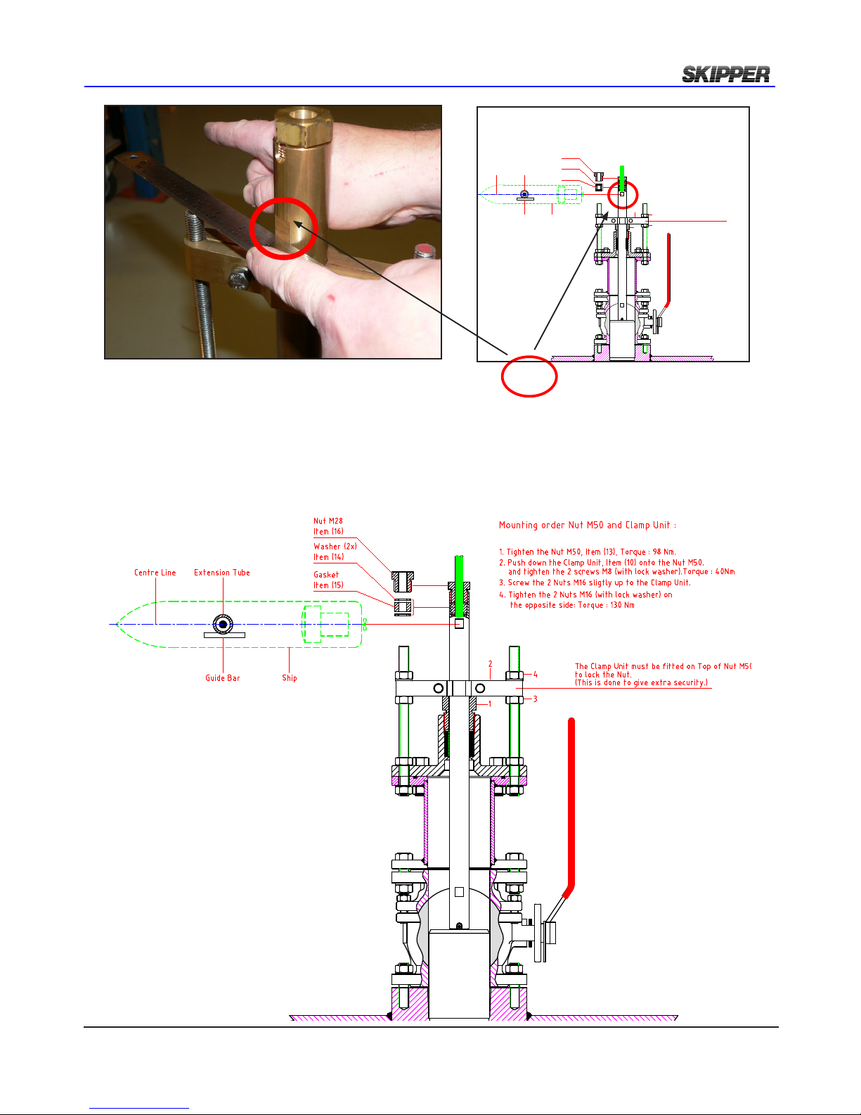
A at object points fore/aft. The at side should be on the port side.
DB-2039
Nut M28
DB-2037
Washer (2x)
Gasket
DB-2038
Final Assembly
1. Tighten the Nut M50 (DB-2036). Torque : 98 Nm
2. Push down the Clamp Unit (DB-2033) onto the Nut M50.
and tighten the 2 screws M8 (with lock washer).Torque : 40Nm
3. Screw the 2 Nuts M16 sligtly up to the Clamp Unit.
4. Tighten the 2 Nuts M16 (with lock washer) on
1
2
3
4
Mounting order Nut M50 and Clamp Unit :
the opposite side: Torque : 98 Nm
The Clamp Unit must be fitted on Top of Nut M50
to lock the Nut.
(This is done to give extra security.)
Extention TubeCente Line
Guide Bar Ship
Secure sensor by tightening clamping unit and nut M50

Page 16 of 60 2018-05-28
Installation DL2 Doppler Speed Log System
CHAPTER 3: WIRING
The JB70D2-SA does not contain a physical switch (only software) and should be connected to a
circuit breaker for removal of power.
Power may be nominal 24V DC (No more than 32V DC) and/or 115-220V AC. Max 60W typical 15W.
The AC input is an optional back up for JB70D2-SA only. The operator unit CU-M001-SA requires a
24V DC power supply.
There are no input fuse on the CU-M001-SA or JB70D2-SA.
The power input should be including a fuse rated for 100% - 200% of max power installed components.
Example: A 24V DC to power both CU-M001-SA and JB70D2-SA should have a 3A slow blow fuse.
clamping The cables
Cables should be connected to WAGO connector, leaving
approximately 3 cm of tail. They should be stripped with 6-7 mm of
metal showing and these should be connected as in the diagram
above. A small screwdriver with blade size approx 3.5 mm can be
used. WAGO part no 210-719 is ideal for this use.
Outer shields should be collected and grounded in a ground stud on
the edge of the cabinet. The outer insulation should be cable tied to
the plastic handle of the connector, and securely anchored nearby.
The plugs when retted, must be installed such that their clips are
fully in the up position.
220V AC. 0,5A
115V AC. 1A
24V DC. 3A

2018-05-28 Page 17 of 60
Installation DL2 Doppler Speed Log System
cu-m001-sa OperaTOr uniT wiring
The operator unit has 2 connectors.
1 LAN connector for communication with Electronic unit.
2: WAGO connector CN1 for 24V power. Max 10W, Typical 6W.
Items supplied with CU-M001
1 x ZZN-01120.
Connector Female w/ejectors 6x2 pole, black. (CN 1)
1 x ZZN-01123. Strain relief plate, 6x2 pole, width 11 mm. (CN 1)
Note:
NMEA and
CANBUS are
options not yet
implemented

Page 18 of 60 2018-05-28
Installation DL2 Doppler Speed Log System
Jb70d2-sa elecTrOnic uniT wiring
The JB70D2-SA is connected with Operator unit CU-M001 with the LAN connectors. The second
LAN connector may be used for set up/ service purpose.
PWR 3
Not in use on DL2
Power in PWR 2
24V DC
Power in PWR1
115-220V AC
Sensor J3
NMEA J1
2 x NMEA In
4 x NMEA Out
AUX/Alarm J2
Alarm relay
1 x AUX In
2 x AUX Out
2 x LAN

2018-05-28 Page 19 of 60
Installation DL2 Doppler Speed Log System
ZZN-01126 Relief Housing,
3 pole snap-on.
WAGO: 232-633
ZZN-01125 Plug, Female 3
pole,231-303 026
ZZN-01124 Plug, Female 2
pole, 231-302_032-000
ZZN-01123 Strain relief
plate, 6x2 pole, width 11 mm
WAGO 713-126
ZZN-01120 Connector Fe-
male w ejectors 6x2 pole, black
WAGO 713-1106/037-000
ZZN-01123 Strain relief
plate, 6x2 pole, width 11 mm
WAGO 713-126
ZZN-01130 Connector, Fe-
male w/ejectors 3x2 pole, black
WAGO 713-1103/037-000
cOnnecTOrs supplied wiTh Jb70d2

Page 20 of 60 2018-05-28
Installation DL2 Doppler Speed Log System
sensOr cOnnecTiOn J3
The sensor is connected to JB70D2-SA Connector J3. 6 pin WAGO connector.
The cable screen is connected to screen on sensor side and does not need to be grounded at
JB70D2-SA side, if the system has instability problems grounding at the JB70 unit may help. .
J3 Pin1
1
6
5
4
3
2
Other manuals for DL2
2
Table of contents


