Skoda SUPERB User manual

Order Number/ Objednací číslo/ Bestellnummer
Fitting instructions/ Montážní návod/ Montageanleitung
Superb (3V)
3V0 054 634, 3V0 054 634A
Parkovací kamera
Rückfahrkamera
REVERSING CAMERA
REVERSING CAMERA
Notes to the text/ Poznámky k textu/ Anmerkungen zum Text
Caution.
Texts with this symbol warn against the risk of injury of the person performing the
assembly, or to potential risk of damage to the vehicle if the operation is performed
improperly.
Pozor.
Texty s tímto symbolem upozorňují na možnost poranění osoby provádějící montáž
popř. možnost poškození vozu při neopatrném provedení operace.
Achtung.
Texte mit diesem Symbol weisen auf Verletzungsgefahren bei Personen oder auf
eventuelle Beschädigungen des Wagens bei unachtsamer Durchführung der Operation
hin.
Attention.
Texts with this symbol contain instructions emphasizing accuracy of performance of
particular operation.
Upozornění.
Texty s tímto symbolem obsahují pokyny s důrazem na přesnost provedení dané
operace.
Hinweis.
Texte mit diesem Symbol enthalten Hinweise auf die Ausführungsgenauigkeit der
jeweiligen Operation.
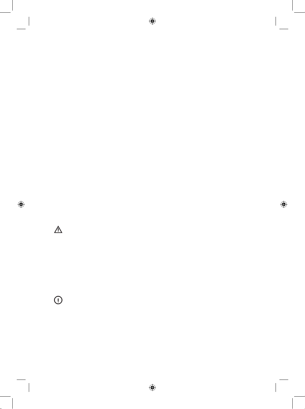
7,5 A
3V0 054 634
3V0 054 634A
3V0 054 634B
3V0 054 634C
B
A
H
G
J
40x
D
E
2x
F
C
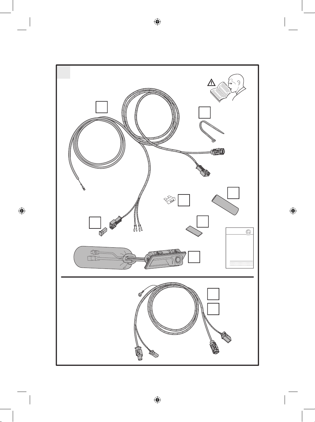
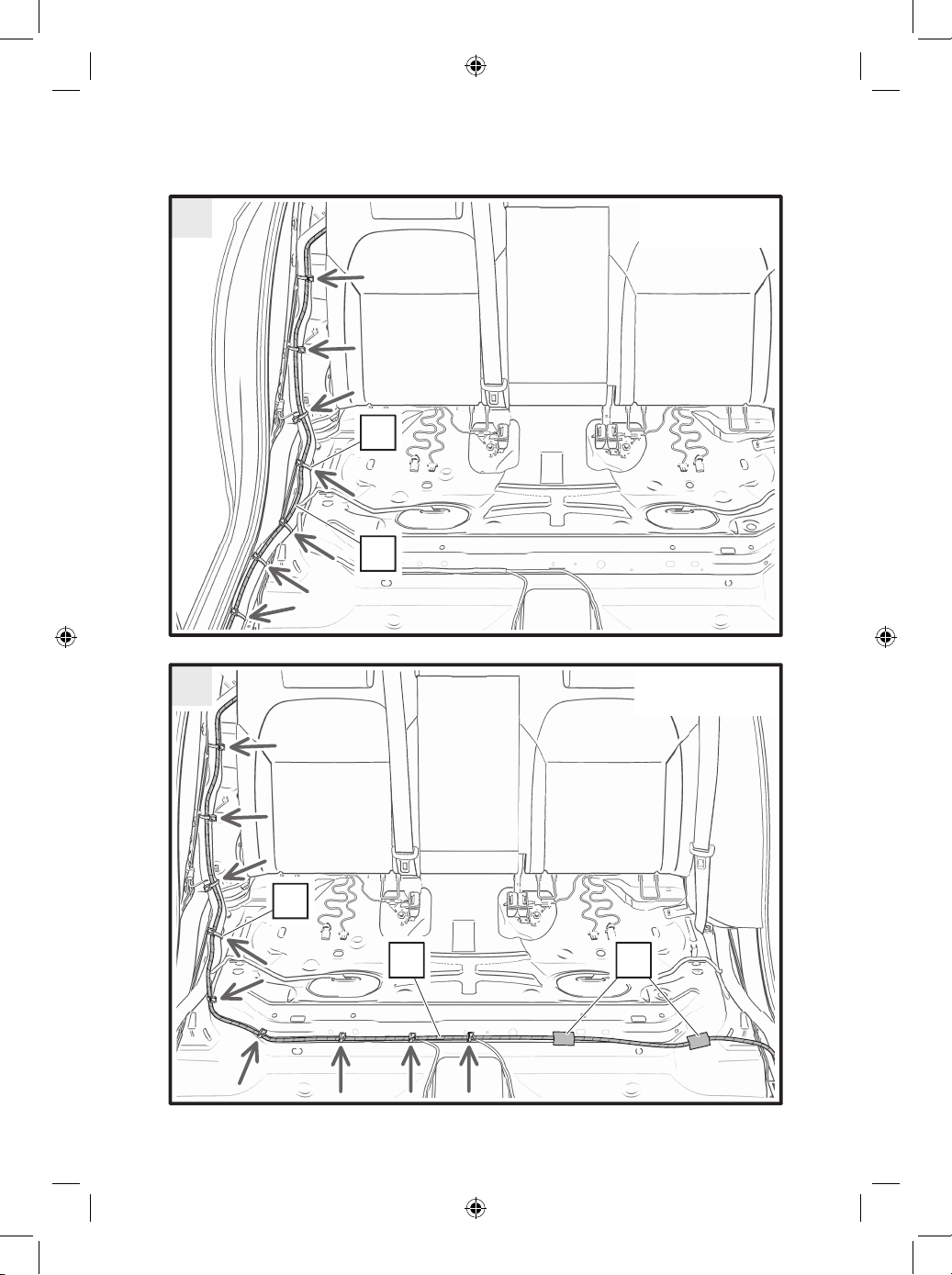
1
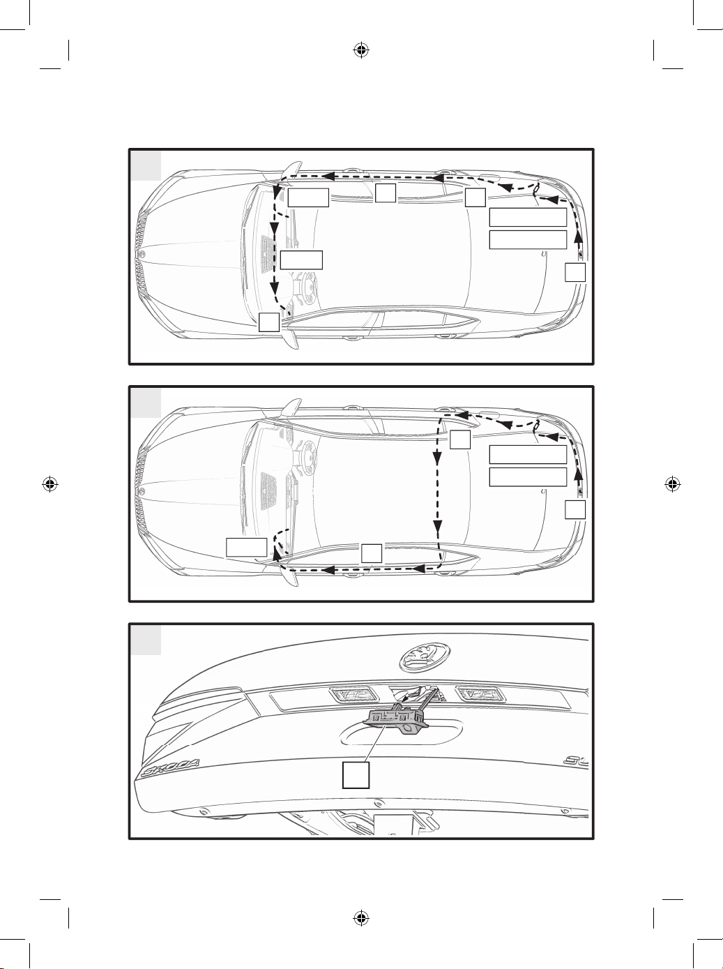
4
9
11
16, 17
5B, 6B, 7B
5A, 6A, 7A
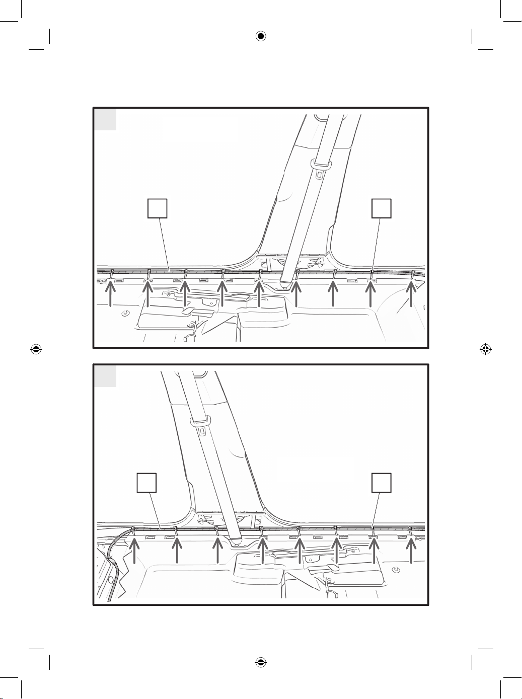
B
4
8
10
15
13, 14
5B, 6B, 7B
5A, 6A, 7A
12, 17
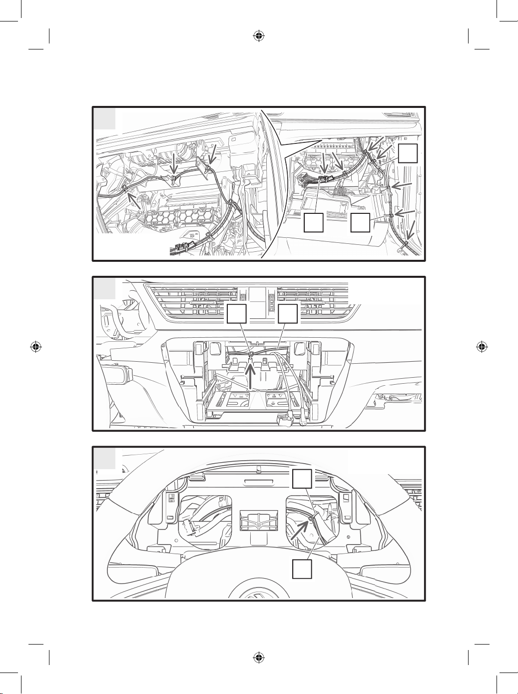
2
3
4

1
Mu 9 Nm
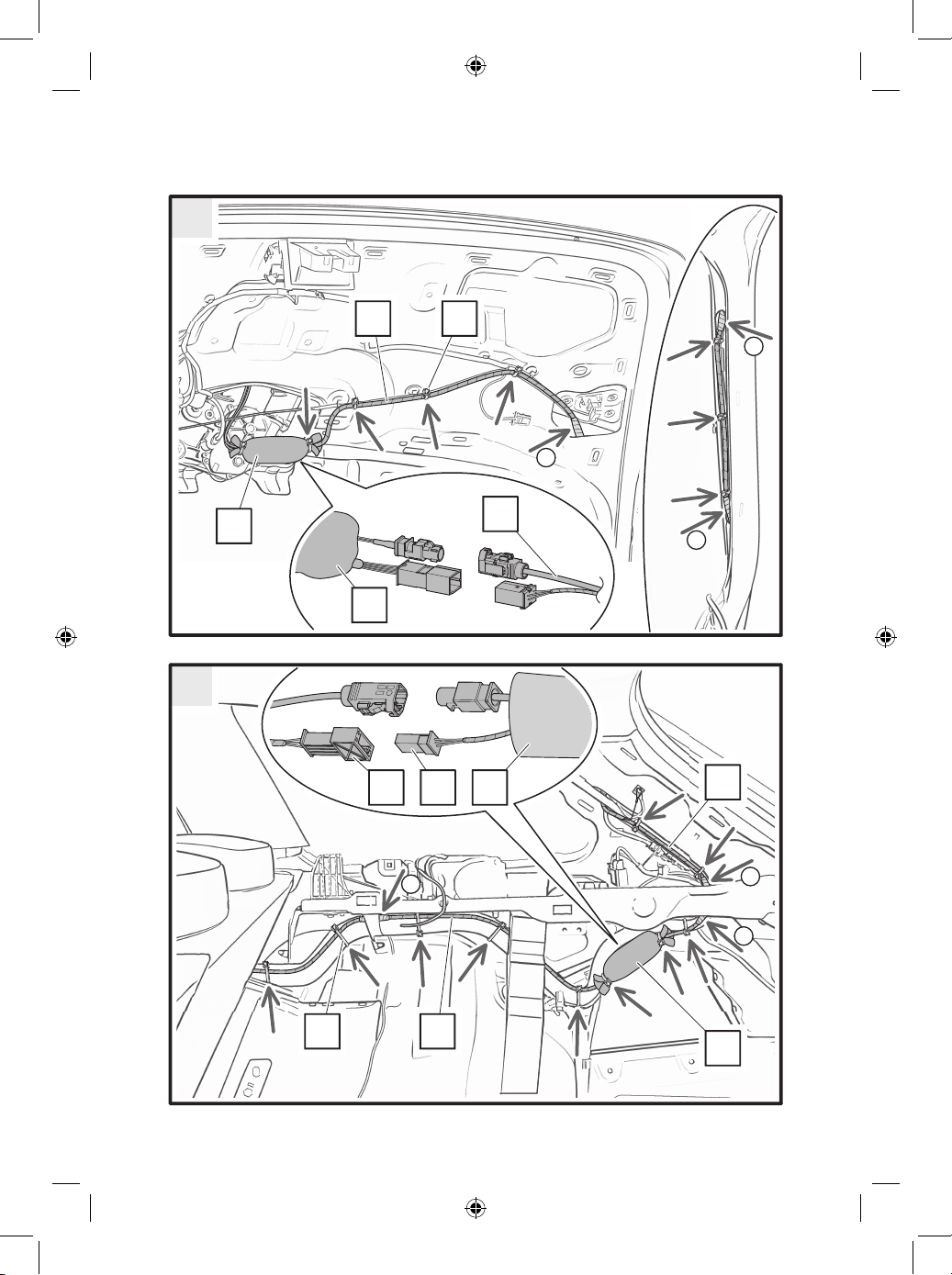
B
H
HA
B
H
H DB
1
1
1
5A
6A

E
H
D
A
E
A
1
Mu 2 Nm
B
J
J
A
7A
5B
1
1
1
B
D
B
J
J
1
1
1
E
D A E
AJ
J
6B
7B
A
D
Applies for left steering.
Platí pro levostranné řízení.
Gilt für Linkslenkung.
A F
D
Applies for right steering.
Platí pro pravostranné řízení.
Gilt für Rechtslenkung.
8
9
DA
Applies for left steering.
Platí pro levostranné řízení.
Gilt für Linkslenkung.
DA
Applies for right steering.
Platí pro pravostranné řízení.
Gilt für Rechtslenkung.
10
11
D
A
C
Applies for left steering.
Platí pro levostranné řízení.
Gilt für Linkslenkung.
AD
Applies for left steering.
Platí pro levostranné řízení.
Gilt für Linkslenkung.
A
D
Applies for left steering.
Platí pro levostranné řízení.
Gilt für Linkslenkung.
12
13
14
Other manuals for SUPERB
10
This manual suits for next models
2
Table of contents
Languages:


