Toyota CAMRY PT949-08210 User manual

TOYOTA CAMRY (GAS AND HV) 2022- DASHCAM (Digital Video Recorder)
Preparation
Page 1 of 16 pages
Issue: A07/25/2021
Part Number: PT949-08210 (Dashcam)
PT949-48210 (Y-Harness)
Dashcam Kit Contents
Item #
Quantity Reqd.
Description
1
1
Dashcam Main Unit
2
1
SD Card Holder
3
1
SD Card (16 GB)
4
1
Window Mounting Plate
5
1
Foam Tape
6
2
Cable Ties
7
1
Quick Start Guide
Y-Harness Kit Contents
Item #
Quantity Reqd.
Description
1
1
Mirror Patch Y-Harness
2
2
Foam Tape
3
4
Cable Ties
Additional Items Required For Installation
Item #
Quantity Reqd.
Description
1
1
PT949-08210 (Dashcam Unit)
2
1
PT949-48210 (Y-Harness)
Conflicts
N/A
Recommended Tools
Personal & Vehicle
Protection
Notes
Seat Protection
Dash Protection
Special Tools
Notes
PT949-IAD0E Install Aid
For Port Installations Only
Installation Tools
Notes
Panel Tool
Socket Wrench
With 10 mm Socket
Torque Wrench
With 10 mm Socket
Hooked Panel Tool
Needle Nose Pliers
For Sun Visor Clip Removal
Special Chemicals
Notes
VDC Approved Cleaner
To Clean Windshield
General Applicability
All Models
Recommended Sequence of Application
Item #
Accessory
1
Y-Harness (PT949-48210)
2
Dashcam (PT949-08210)
*Mandatory
Vehicle Service Parts (may be required for reassembly)
Item #
Quantity Reqd.
Description
1
Up to 2 pcs
Roof Console Clips if damage
occurs during removal.
P/N: 90467-09240
2
3
4
Kit Service Parts (may be required in future)
Item #
Part Number
Description
1
PT949-08210-AA
Camera Unit + SD
2
PT949-08210-AB
SD Card 16GB Industrial
3
PT949-08210-AC
Sd Card Holder Assembly
4
PT949-08210-AD
Window Plate with Tape
Legend
STOP:
Damage to the vehicle may occur. Do not
proceed until process has been complied with.
OPERATOR SAFETY:
Use caution to avoid risk of
injury.
CAUTION:
A process that must be carefully observed
in order to reduce the risk of damage to the
accessory/vehicle and to ensure a quality installation.
TOOLS & EQUIPMENT:
Used in Figures calls out the
specific tools and equipment recommended for this
process.
REVI
SION MARK: This mark highlights a change in
installation with respect to previous issue.
SAFETY TORQUE:
This mark indicates that torque is
related to safety.
REGULATORY MARK:
This mark indicates the
component is related to regulatory compliance

TOYOTA CAMRY (GAS AND HV) 2022 - DASHCAM (Digital Video Recorder)
Procedure
Page 2 of 16 pages
Issue: A07/25/2021
Care must be taken when installing this accessory to ensure damage does not occur to the vehicle. The installation of this
accessory should follow approved guidelines to ensure a quality installation.
These guidelines can be found in the "Accessory Installation Practices" document.
This document covers such items as:-
•Vehicle Protection (use of covers and blankets, cleaning chemicals, etc.).
•Safety (eye protection, rechecking torque procedure, etc.).
•Vehicle Disassembly/Reassembly (panel removal, part storage, etc.).
•Electrical Component Disassembly/Reassembly (battery disconnection, connector removal, etc.).
Please see your Toyota dealer for a copy of this document.
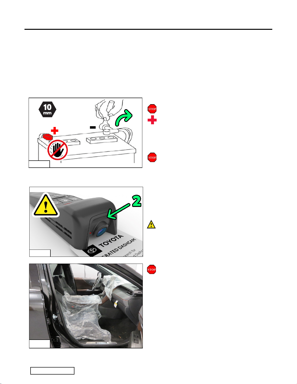
1. Disconnect Battery
(a) Protect the fender before starting.
(b) The engine components and coolant may be
hot.
(c) Remove the vehicle’s 12V battery negative
terminal (Fig 1-1).
(d) Do NOT touch or disconnect high voltage
systems on a Hybrid Vehicle.
CAUTION: Do not touch the positive terminal
with any tool during battery disconnection.
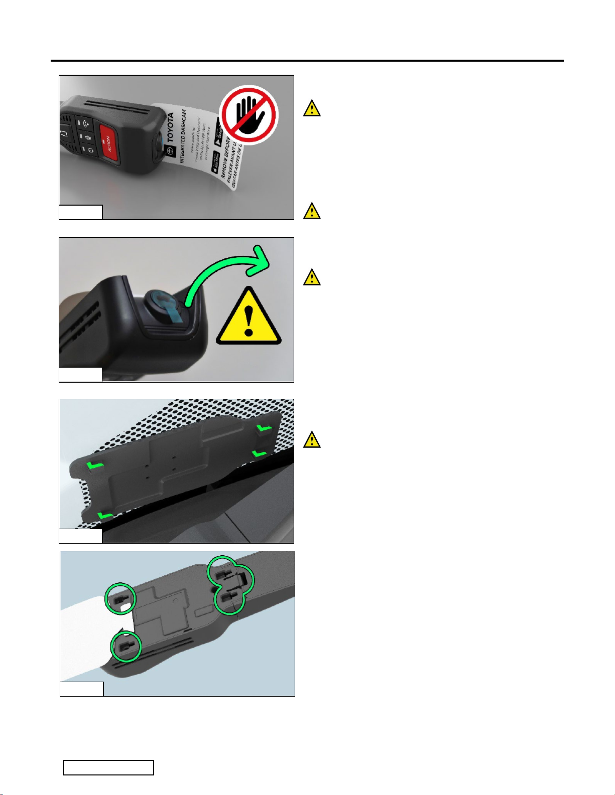
2. Kit Preparation
(a) Check the Dashcam Kits for missing
contents or damage.
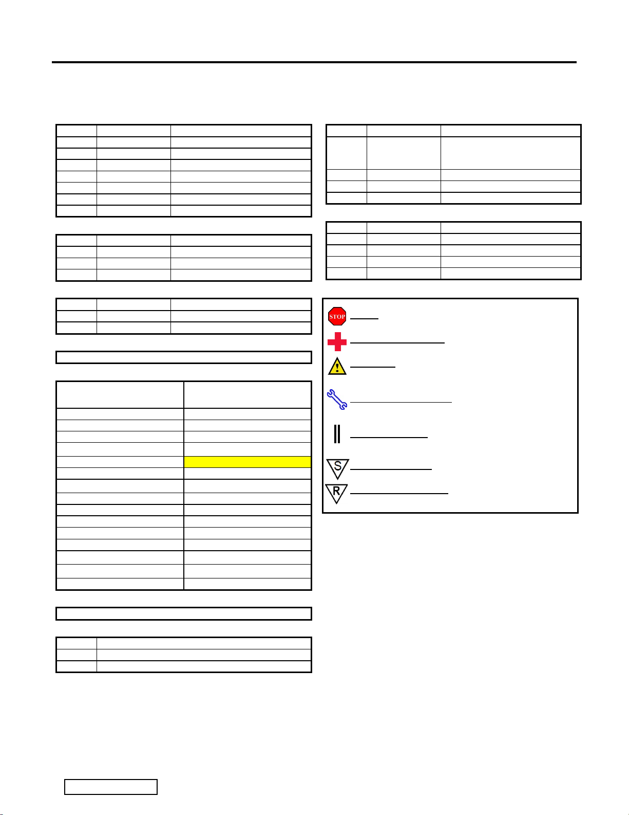
(b) Confirm Camera Angle Position – 2 visible
recessed lines should be seen below the
lens with the camera held in the as-installed
orientation. (Fig 2-1, Note: Camera is upside
down in the image)
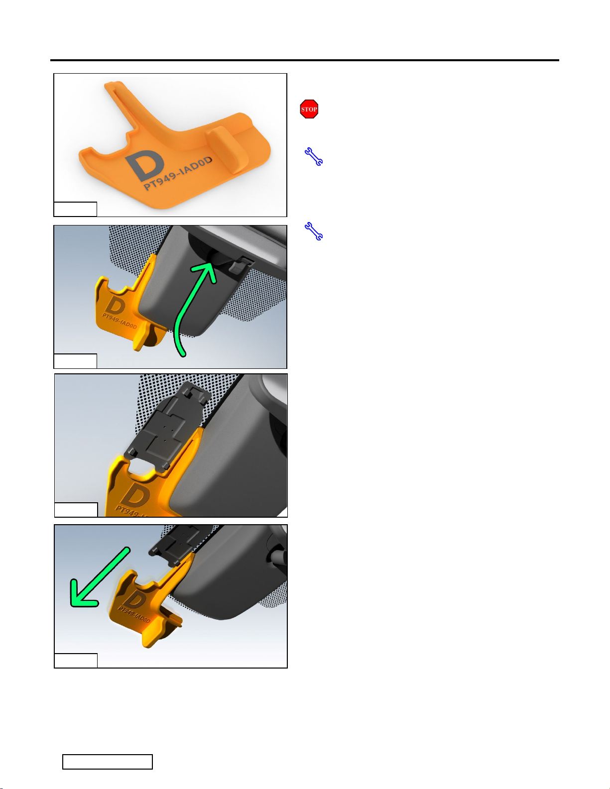
(c) If this is not correct, please see adjustment
instructions at the end of this document
(Step 17) NOTE: Do not try to force it as
there is a hidden lock screw on each side.
3. Vehicle Protection
(a) Apply Vehicle Protection to front seats,
dashboard, and center console. (Fig 3-1)
Fig. 2-1
Fig. 1-1
Fig 3-1

TOYOTA CAMRY (GAS AND HV) 2022 - DASHCAM (Digital Video Recorder)
Procedure
Page 3 of 16 pages
Issue: A07/25/2021
4. Install Windshield Base Plate
STOP: The front windshield must be
at least 50°F (10°C).
(a) For PPO Installations, please use 3D
hard template with the part number
“PT949-IAD0D” (Fig 4-1) and follow
steps (c) through (f).
(b) For Dealer Installations or in the case
that the 3D hard template is unavailable,
please follow steps (g) through (i)
(c) On the driver’s side of the vehicle, using
window cleaner and a lint free cloth,
clean the windshield area next to the
TSS cover.
(d) Insert the 3D Template (PT949-IAD0C)
between the TSS cover and the
windshield glass on the drivers side of
the TSS cover, it should fit snugly
against the TSS cover side walls, and
the features of the template should allow
it to stay in place hands free. If not, apply
a small bit of tape for support to the
lower edge. (Fig 4-2)
(e) Remove adhesive and stick mounting
plate on windshield while aligning to the
lower and right side edges of the
mounting plate. Press firmly to reduce
visible air pockets. Note that the narrow
end of the plate is towards the top of the
windshield. (Fig 4-3)
(f) Remove the 3D hard template by gently
pulling towards the base of the
windshield (wiper cowl area) to slide it
out from under the TSS cover. (Fig 4-4)
Fig. 4-1
Fig. 4-2
Fig.4-4
Fig. 4-3

TOYOTA CAMRY (GAS AND HV) 2022 - DASHCAM (Digital Video Recorder)
Procedure
Page 4 of 16 pages
Issue: A07/25/2021
For Dealer Installations / No 3D Hard
Template Available:
(g) Using scissors, cut the paper template as
indicated. For PPO Installations, please
use 3D hard template provided.
(h) Referencing the TSS cover, align to the
indicated line and affix the template to
the windshield using tape. (Fig 4-5)
(i) Remove adhesive and stick mounting
plate on windshield paying attention to
the reference lines on template. Press
firmly to reduce visible air pockets. Note
that the narrow end of the plate is
towards the top of the windshield.
(Fig 4-6)
(j) Once the base plate is fitted, remove
template in the direction towards the
lower edge of the windshield and clean
any tape residue from the glass.
All Installation types continue from here
onwards.
5. Remove Visor Mount Clips and Base
(a) Remove the Sun Visor Hooks on BOTH
Driver and Passenger side of the Map
Light Console, to allow for gentle pulling
down of the headliner without damage.
Note: Both sides remove in the same
direction, Passenger side is not mirrored.
(1) Twist the Visor Hook Anti-Clockwise
and pull down to release hook
component. (Fig 5-1)
(2) After removing the hook component,
release the two tabs and pull out the
base, needle nose pliers
recommended.
Fig. 4-5
Fig. 4-6
Fig. 5-1

TOYOTA CAMRY (GAS AND HV) 2022 - DASHCAM (Digital Video Recorder)
Procedure
Page 5 of 16 pages
Issue: A07/25/2021
6. Remove Roof Map Light Console
(a) Remove the roof console by pulling down
firmly on the forward edge (towards the
front of the vehicle). Pull down to release
2 clips then slide forwards and down to
unhook the rear edge (Fig 6-1)
(1) A plastic panel removal tool may be
used to pull down on the console.
(2) CAUTION: Do not pry against the
headliner or it will leave visible
damage.
(3) Note clips appearance in the image to
better understand the removal
process. (Fig 6-2)
(b) Once fully detached, disconnect the wire
harness from the roof console and place
the console in a safe place to avoid
damage.
(c) Inspect the console clips and replace if
damaged (P/N: 90467-09240, 2 PCS)
7. Remove the TSS Cover
(a) Start by rotating the mirror approximately
45 degrees to improve access to the
sides of the TSS cover while retaining
access directly above the mirror.
(Fig 7-1)
Fig. 6-1
Fig. 6-2
Fig.7-1

TOYOTA CAMRY (GAS AND HV) 2022 - DASHCAM (Digital Video Recorder)
Procedure
Page 6 of 16 pages
Issue: A07/25/2021
(b) Holding the TSS Cover firmly with both
hands, move it downwards towards the
windshield wiper cowl area by
approximately 10 mm, without fully
removing it. This is to get better access
to remove the cover around the mirror
(Fig 7-2)
(c) While supporting the main cover, pull
down on the smaller inset cover around
the mirror mount, using either your
hooked panel removal tool or your
fingertips, to detach the smaller cover
from the main TSS cover. Take care not
to scratch the headliner in the process.
(1) Pull down on the upper rearward
edge of the cover plate (closest to the
headliner) to disengage the clips.
(Fig 7-3), (Fig 7-4)
(2) Alternatively you can gently pull down
on the headliner, reach through the
Map Light Console opening and push
down on the upper rearward edge of
the cover plate
(3) Slide the smaller cover up and to the
rear of the vehicle to disengage the
lower hooks.
(d) Remove the TSS main cover by sliding
the cover down (Fig , shown from the
back side for clarity) from the TSS cover
base in the direction of the bottom of the
windshield / towards the wiper cowl area.
Both covers should now be fully
removed. (Fig 7-5)
Fig. 7-2
Fig. 7-3
Fig. 7-4
Fig. 7-5

TOYOTA CAMRY (GAS AND HV) 2022 - DASHCAM (Digital Video Recorder)
Procedure
Page 7 of 16 pages
Issue: A07/25/2021
8. Install the Y-Harness
(a) Disconnect the mirror power harness in
on the release tab. The mirror harness is
the 10-pin connector, outboard to the
passenger side. (Fig. 8-1), (Fig 8-2)
(b) Install the Y-harness between the mirror
and the vehicle mirror wire harness
connector.
(1) Gently pull the vehicle’s Power Mirror
connector back inside the Map Light
Console Area (Fig. 8-3)
(2) Insert the male mirror connector into
the Y-Harness black female
connector.
(3) Apply the supplied Foam Tape to
insulate the connector from rattles.
Gently feed the black Y-Harness male
connector back to the TSS area and insert
into the female mirror connector affixed to
the mirror base. (Fig. 8-4)
Fig. 8-1
Fig. 8-2
Fig. 8-3
Fig. 8-4

TOYOTA CAMRY (GAS AND HV) 2022 - DASHCAM (Digital Video Recorder)
Procedure
Page 8 of 16 pages
Issue: A07/25/2021
(4) Pull the remaining slack harness back
into the headliner / map light console
area as per the image. (Fig 8-5)
9. Route Dashcam Harness through the
Headliner
(a) From the driver’s side of the windshield,
locate the notch in the front edge of the
headliner if available (Fig 9-1)
(b) Route the Dash Cam pigtail through the
notch or similar area, and into the
headliner. Take care not to crease the
headliner in the process. (Fig 9-2)
(c) Feed the Dashcam harness through to
the open Map Light Console area.
(Fig 9-3)
Fig. 8-5
Fig. 9-1
Fig. 9-2
Fig. 9-3

TOYOTA CAMRY (GAS AND HV) 2022 - DASHCAM (Digital Video Recorder)
Procedure
Page 9 of 16 pages
Issue: A07/25/2021
(d) Connect the Dashcam pigtail harness to
the newly fitted Y-harness that was fitted
in step 7. (Fig 9-4)
(e) Apply the supplied Foam Tape to
insulate the connectors from rattles.
(Fig 9-5)
10.Reinstall the TSS Cover
(a) Reinstall the TSS cover by pushing up
on the cover along the windshield in the
direction towards the headliner to
engage the mounting clips into the cover
base. (Fig 10-1)
(b) Reinstall the mirror cover plate by
hooking the front hooks into the edge of
the TSS main cover opening and push
up on the mirror cover to engage the
clips to the main cover. (Fig 10-2)
Fig. 9-4
Fig. 9-5
Fig. 10-1
Fig. 10-2

TOYOTA CAMRY (GAS AND HV) 2022 - DASHCAM (Digital Video Recorder)
Procedure
Page 10 of 16 pages
Issue: A07/25/2021
11.Fitting the Dashcam to Base Plate
NOTE: The Hang Tag that is attached to the
Dashcam is only to be removed by the
end user. As the camera turns on with
ignition, the hang tag is intended to block
recording while the vehicle is being
processed through areas which may be
confidential / contain unreleased vehicles.
Do NOT remove the hang tag, please
handle it with care to prevent accidental
removal. (Fig 10-1)
(a) IMPORTANT: DO remove the Semi-
Transparent Blue Film protective cover
from the camera lens before fitting the
camera to the vehicle. Handle the
camera with care after removing. Ensure
the film cover is not left behind in the
vehicle and is properly discarded.
(Fig 11-2)
NOTE: Observe the shape of the T-hook
features for the Dashcam to lock on to. The
hooks face upwards towards the headliner.
(Fig 11-3)
(b) The Dashcam is affixed to the window by
sliding on to these 4 T-hooks and
allowing the clip to engage. (Fig 11-4)
Fig. 11-1
Fig. 11-2
Fig. 11-3
Fig. 11-4

TOYOTA CAMRY (GAS AND HV) 2022 - DASHCAM (Digital Video Recorder)
Procedure
Page 11 of 16 pages
Issue: A07/25/2021
(c) Hook the Dashcam wire extension cover
hooks into the leading edge of the
headliner
(d) Swing the Dashcam unit up towards the
base plate. Check for alignment of the 4
T-hooks
(e) Push the dashcam unit in towards the
windshield to ensure all 4 T-hooks are in
the correct starting point. All sides should
have a consistent gap to the glass.
(f) `Slide the Dashcam down towards the to
the T-hooks and engage the clip that
secures it. Adjust the telescopic wire
harness cover as required to sit correctly,
and confirm the hooks are tucked inside
the leading edge of the headliner.
Fig. 11-7
Fig. 11-6
Fig. 11-5
Fig. 11-8

TOYOTA CAMRY (GAS AND HV) 2022 - DASHCAM (Digital Video Recorder)
Procedure
Page 12 of 16 pages
Issue: A07/25/2021
12.Route / Bundle Wire Harness
(a) Before proceeding with securing the
harness, confirm that both connector
pairs and fuse holders have been
protected with the provided foam tape.
Use the provided foam tape to minimize
any potential rattle concerns. (Fig 12-1)
(b) Secure the Y-harness and fuse holders
against the existing harnesses at the
front edge of the map light / sunglasses
pocket opening. (Fig 12-2)
(c) Secure the Dashcam Pigtail harnesses
against the existing harnesses on the
driver’s side of the map light / sunglasses
pocket opening. Loop and bundle them
as required. Arrange this in a way that
does not obstruct the console being
reinstalled. (Fig 12-2)
(d) Ensure that the connection for the
console is still free to be connected and
that the bundled harnesses are not
obstructing the console map light
connector. (Fig 12-3)
(e) Note: Take care not to cause bulging
in the headliner. Some adjustments to
the bundle may be required to avoid
bulging the headliner.
(f) Note: Do not block access to the clip
holes in the body structure or the roof
console may not fit properly.
(g) After securing, be sure to snip off extra
cable-tie length to prevent any rattles or
squeaks from the loose end of the cable
tie strap.
Fig. 12-1
Fig. 12-2
Fig. 12-3

TOYOTA CAMRY (GAS AND HV) 2022 - DASHCAM (Digital Video Recorder)
Procedure
Page 13 of 16 pages
Issue: A07/25/2021
13.Reinstall Overhead Console
(a) Re-connect harness for the overhead
console, test map lights and sunroof
control if equipped. (Fig 13-1)
(b) Check all console clips are in good
condition and are present on the
console. If any are still installed in the
roof of the vehicle and have separated
from the console, a panel tool with a
forked end can be used to pry them out,
then reinstall in the console. (Fig 13-2)
(c) Reinstall the console by first inserting the
tabs to the rear (of the car) of the
opening and then rotate upwards in the
front of the console to pop in the two
clips. Observe marks in headliner for
alignment references. Carefully push in
to place to lock.
(d) Note: Be careful aligning the clips to
holes to avoid damage.
14. Reinstall Sun Visor Clips
(a) Insert the clip bases on both sides of the
map light console, they should snap
securely into place.
(b) Insert the visor clips starting with the
opening for the visor in the anti-clockwise
position similar to how they were
removed, then rotate clockwise to lock
back into place.
(c) Note: The direction is the same for both
sides. It is not mirrored.
15. Reconnect Vehicle Battery
(a) Reconnect the Negative Battery Cable.
(b) Torque to 5.4 N•m (48 in•lbsf)
(c) CAUTION: Do not touch the positive
terminal with any tool.
16.Owner’s Manual
Place the Owner’s Manual
(“Quick Start Guide”) in the glove box with
the other vehicle owner’s manuals.
Torque Wrench
Fig. 15-1
Fig. 13-1
Fig. 13-2
Fig. 14-1

Page 14 of 16 pages
Issue: A07/25/2021

TOYOTA CAMRY (GAS AND HV) 2022 - DASHCAM (Digital Video Recorder)
Procedure
Page 15 of 16 pages
Issue: A07/25/2021
17.Camera Angle Adjustment
In case the camera angle adjustment
does not match what is intended for this
vehicle (2 visible recessed lines under
the lens) then this angle can be adjusted
as follows. (Fig 17-1)
DO NOT try to force the lens to move the
camera – it is locked in place and
damage may occur.
(a) Using a 1.5 mm size Allen Key tool,
insert the tool in the lowest and forward
most holes on either side, where you will
see small lock screw heads. Turn the
screws counter clockwise approximately
2-3 turns to release the pressure on the
locks. Do not fully remove these
screws. (Fig 17-2)
(b) With the locks on both sides now loose,
you can raise or lower the camera view
angle. For this vehicle we are looking to
see two recessed rib lines below the
camera lens to indicate the correct view
angle. (Fig 17-3)
(c) Once the angle is corrected, retighten
the locking screws on each side, then
reconfirm the two recessed rib lines to
ensure the camera has not moved while
tightening the locks. (Fig 17-3)
(d) Optional: Use the Live View feature of
the Toyota Integrated Dashcam phone
application to confirm the view angle if
compensating for other accessories /
obstructions.
Note: When connecting for the first time
as an installer, choose “Remind Me
Next Time” when you are prompted to
change the WI-FI password.
Fig. 17-1
Fig. 17-2
Fig. 17-3

TOYOTA CAMRY (GAS AND HV) 2022 - DASHCAM (Digital Video Recorder)
Checklist - these points MUST be checked to ensure a quality installation.
Check: Look For:
Page 16 of 16 pages
Issue: A07/25/2021
Accessory Function Checks
Verify parts
Vehicle Startup
Power LEDs light up
Remove Blue Film on Dashcam Lens
Vehicle Function Checks
Standard exterior lights - low / high beams,
left / right turn signal, emergency signal
Roof Console functions – map lights,
sunroof / panoramic roof controls if
equipped.
EC Mirror – Confirm power and dimming.
Mirror – View Angle
TPMS Gauge Indicator
Removed items have been discarded &
replaced items are in place
Confirm Dashcam does not emit a
continuous beep on vehicle startup. If it
does, confirm SD card is installed
Blue Lens Protector Film should be
removed and discarded.
Confirm standard lighting functions work
properly.
Confirm roof console functions work
properly.
Confirm EC Mirror power status LED
visible, cover the transparent lens on the
reverse side with your hand, the mirror
glass should fade darker after a few
seconds.
Confirm mirror is adjusted correctly for
visibility for the average driver.
Prior to TPMS activation and PDS, the
TPMS light may blink when IG is on. After
activation and PDS, the TPMS light should
turn off when IG is on.
Vehicle Appearance Check
After accessory installation and removal of
protective cover(s), perform a visual
inspection.
All Templates and Tools removed from the
vehicle.
Ensure no damage (including scuffs and
scratches) was caused during the
installation process.
(For PPO installations, refer to TMNA
Accessory Quality Shipping Standard.)
Confirm Windshield Template and all tools
have been removed from the vehicle.
This manual suits for next models
1
Table of contents
Other Toyota Dashcam manuals

Toyota
Toyota N656 User manual

Toyota
Toyota PK6A3-33HT1 User manual

Toyota
Toyota PT949-34220 User manual

Toyota
Toyota PZQ90-89011 User manual

Toyota
Toyota PZQ85-33270 Install guide

Toyota
Toyota PZQ85-33270 Install guide

Toyota
Toyota VENZA PT949-08210 User manual

Toyota
Toyota 2.0 Series User manual

Toyota
Toyota PT949-34222 User manual