Skope CL Series User manual
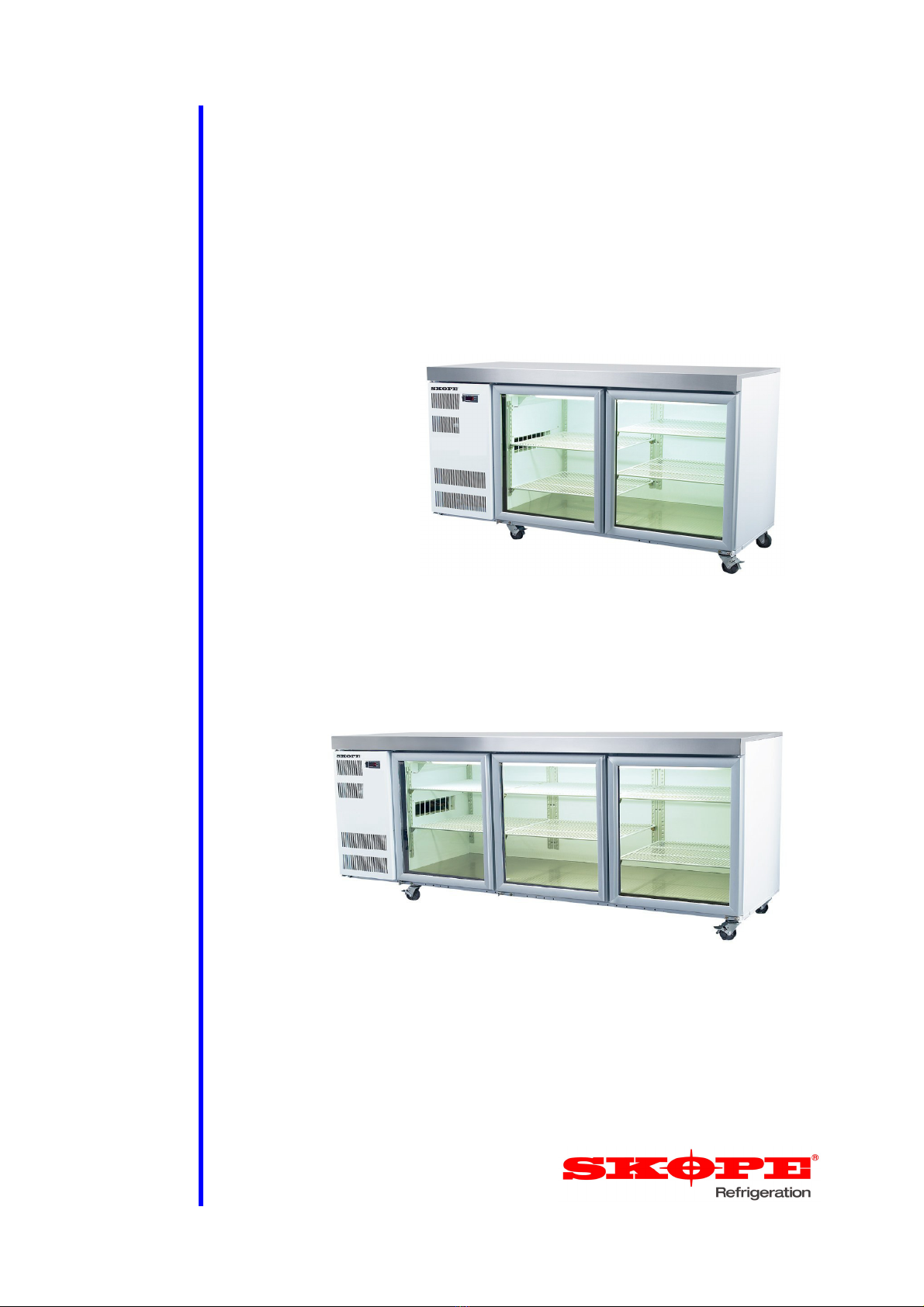
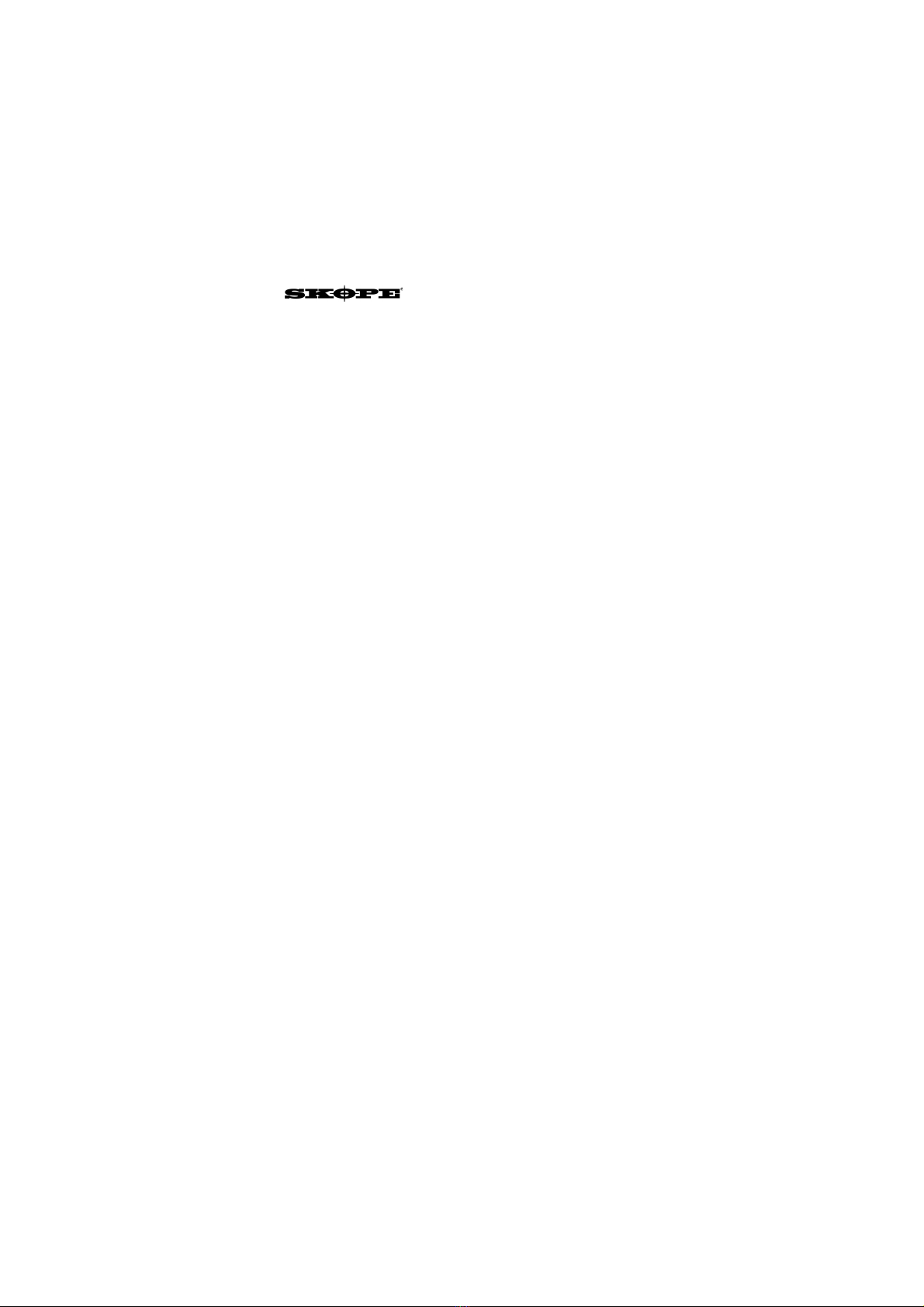
CL & CC Series
SKOPE Counterline & Slimline Horizontal Chiller
Service Manual
MAN0682 Rev. 3.0 Feb. 2014
Model: CL400
Model: CL600
CC & CL Series
SKOPE Counterline & Slimline Horizontal Chiller
Service Manual
MAN0682
Rev. 3.0 Feb. 2014
© 2007 SKOPE Industries Limited. All rights reserved.
SKOPE Industries Limited reserve the right to alter specifications without notice.
is a registered trademark of SKOPE Industries Limited.
SKOPE INDUSTRIES LIMITED
Head Office
PO Box 1091, Christchurch
New Zealand
Freephone: 0800 947 5673
Fax: (03) 983 3896
E-mail: [email protected]
Website: www.skope.co.nz
Trademark Infringement
The SKOPE trademark on this product is infringed if the owner, for the time being, does
any of the following:
• Applies the trade mark to the product after their state, condition, get-up or packaging
has been altered in any manner
• Alters, removes (including part removal) or obliterates (including part obliteration) the
trade mark on the product
• Applies any other trade mark to the product
• Adds to the product any written material that is likely to damage the reputation of the
trade mark
Notice of the above contractual obligations passes to:
• Successors or assignees of the buyer
• Future owners of the product

SKOPE Counterline Series
Service Manual iii
CONTENTS
1 Specifications
Counterline Integral . . . . . . . . . . . . . . . . . . . . . . . . . . . . . . . . . . . . 5
Counterline Remote . . . . . . . . . . . . . . . . . . . . . . . . . . . . . . . . . . . . 6
Slimline Integral . . . . . . . . . . . . . . . . . . . . . . . . . . . . . . . . . . . . . . .7
Slimline Remote . . . . . . . . . . . . . . . . . . . . . . . . . . . . . . . . . . . . . . .8
Servicing Tools . . . . . . . . . . . . . . . . . . . . . . . . . . . . . . . . . . . . . . . . 9
2 Electronic Controller
Overview . . . . . . . . . . . . . . . . . . . . . . . . . . . . . . . . . . . . . . . . . . . . . .10
Introduction . . . . . . . . . . . . . . . . . . . . . . . . . . . . . . . . . . . . . . . . .10
Variations . . . . . . . . . . . . . . . . . . . . . . . . . . . . . . . . . . . . . . . . . . . 10
SKOPE Dixell XR30C Controller. . . . . . . . . . . . . . . . . . . . . . . . . . . . 11
Faceplate . . . . . . . . . . . . . . . . . . . . . . . . . . . . . . . . . . . . . . . . . . . 11
Meaning of LEDs . . . . . . . . . . . . . . . . . . . . . . . . . . . . . . . . . . . . .11
Programming the Controller . . . . . . . . . . . . . . . . . . . . . . . . . . . . . 12
Parameters - Dixell XR30C . . . . . . . . . . . . . . . . . . . . . . . . . . . . .14
Display Alarms . . . . . . . . . . . . . . . . . . . . . . . . . . . . . . . . . . . . . . .15
SKOPE CAREL ir33 Controller . . . . . . . . . . . . . . . . . . . . . . . . . . . . .16
Faceplate . . . . . . . . . . . . . . . . . . . . . . . . . . . . . . . . . . . . . . . . . . . 16
Defrost Cycle . . . . . . . . . . . . . . . . . . . . . . . . . . . . . . . . . . . . . . . . 17
Continuous Cycle . . . . . . . . . . . . . . . . . . . . . . . . . . . . . . . . . . . . . 17
Temperature Probes . . . . . . . . . . . . . . . . . . . . . . . . . . . . . . . . . . 17
Alarms . . . . . . . . . . . . . . . . . . . . . . . . . . . . . . . . . . . . . . . . . . . . . . . .19
Programming. . . . . . . . . . . . . . . . . . . . . . . . . . . . . . . . . . . . . . . . . . . 20
Set-Point . . . . . . . . . . . . . . . . . . . . . . . . . . . . . . . . . . . . . . . . . . .20
Controller Reset . . . . . . . . . . . . . . . . . . . . . . . . . . . . . . . . . . . . . . 21
Default Program Configuration . . . . . . . . . . . . . . . . . . . . . . . . . . . 21
BN Parameter Sets . . . . . . . . . . . . . . . . . . . . . . . . . . . . . . . . . . .21
Field Adjustable Programming . . . . . . . . . . . . . . . . . . . . . . . . . . . 21
Display Stability . . . . . . . . . . . . . . . . . . . . . . . . . . . . . . . . . . . . . .24
Parameters . . . . . . . . . . . . . . . . . . . . . . . . . . . . . . . . . . . . . . . . . . 24
3 Wiring
CL400, CL600, CC300 & CC500 (CAREL controller,
fluorescent lights) . . . . . . . . . . . . . . . . . . . . . . . . . . . . . . . . . . . . . 27
CL800 & CC700 (CAREL controller, fluorescent lights) . . . . . . . . 28
CL800r & CC700r (CAREL controller, fluorescent lights) . . . . . .29
CL & CC Integral (CAREL controller, LED lights) . . . . . . . . . . . .30
CL & CC Remote (CAREL controller, LED lights) . . . . . . . . . . . .31
4 Spare Parts
Cabinet Assembly . . . . . . . . . . . . . . . . . . . . . . . . . . . . . . . . . . . . . . .32
Interior Lighting . . . . . . . . . . . . . . . . . . . . . . . . . . . . . . . . . . . . . . . . . 34
Doors. . . . . . . . . . . . . . . . . . . . . . . . . . . . . . . . . . . . . . . . . . . . . . . . . 36
Integral Refrigeration Unit . . . . . . . . . . . . . . . . . . . . . . . . . . . . . . . . . 38
Remote Refrigeration Unit. . . . . . . . . . . . . . . . . . . . . . . . . . . . . . . . .40

SKOPE Counterline Series
Service Manual
iv
5 Replacement Procedures
Lighting . . . . . . . . . . . . . . . . . . . . . . . . . . . . . . . . . . . . . . . . . . . . . . . 41
Glass Swing Door . . . . . . . . . . . . . . . . . . . . . . . . . . . . . . . . . . . . . . . 42
Alignment . . . . . . . . . . . . . . . . . . . . . . . . . . . . . . . . . . . . . . . . . . . 42
Gasket . . . . . . . . . . . . . . . . . . . . . . . . . . . . . . . . . . . . . . . . . . . . . 42
Tension Adjustment . . . . . . . . . . . . . . . . . . . . . . . . . . . . . . . . . . . 42
Torsion Bar Replacement . . . . . . . . . . . . . . . . . . . . . . . . . . . . . . 43
Removal . . . . . . . . . . . . . . . . . . . . . . . . . . . . . . . . . . . . . . . . . . . . 43
Solid Swing Door. . . . . . . . . . . . . . . . . . . . . . . . . . . . . . . . . . . . . . . . 44
Tension . . . . . . . . . . . . . . . . . . . . . . . . . . . . . . . . . . . . . . . . . . . . 44
Removal . . . . . . . . . . . . . . . . . . . . . . . . . . . . . . . . . . . . . . . . . . . . 44
Sliding Glass Door . . . . . . . . . . . . . . . . . . . . . . . . . . . . . . . . . . . . . . 45
Removal . . . . . . . . . . . . . . . . . . . . . . . . . . . . . . . . . . . . . . . . . . . . 45
Gasket . . . . . . . . . . . . . . . . . . . . . . . . . . . . . . . . . . . . . . . . . . . . . 45
Door Rollers . . . . . . . . . . . . . . . . . . . . . . . . . . . . . . . . . . . . . . . . . 45
Tension . . . . . . . . . . . . . . . . . . . . . . . . . . . . . . . . . . . . . . . . . . . . 45
Sliding Door Frame Cover Removal . . . . . . . . . . . . . . . . . . . . . . 46
Refrigeration Unit . . . . . . . . . . . . . . . . . . . . . . . . . . . . . . . . . . . . . . . 47
Unit Front Cover . . . . . . . . . . . . . . . . . . . . . . . . . . . . . . . . . . . . . . 47
Unit Wiring Junction Box . . . . . . . . . . . . . . . . . . . . . . . . . . . . . . . 48
Refrigeration Unit Removal . . . . . . . . . . . . . . . . . . . . . . . . . . . . . 48
Evaporator Fan Replacement . . . . . . . . . . . . . . . . . . . . . . . . . . . 49
Recommended Service Procedures . . . . . . . . . . . . . . . . . . . . . . 49
Electronic Controller . . . . . . . . . . . . . . . . . . . . . . . . . . . . . . . . . . . . . 51
Variations . . . . . . . . . . . . . . . . . . . . . . . . . . . . . . . . . . . . . . . . . . . 51
Spare Parts . . . . . . . . . . . . . . . . . . . . . . . . . . . . . . . . . . . . . . . . . 51
Diagnostics . . . . . . . . . . . . . . . . . . . . . . . . . . . . . . . . . . . . . . . . . 51
CARELController Termination . . . . . . . . . . . . . . . . . . . . . . . . . . . 52
Probe Resistance . . . . . . . . . . . . . . . . . . . . . . . . . . . . . . . . . . . . . 52
6 Maintenance
Cleaning . . . . . . . . . . . . . . . . . . . . . . . . . . . . . . . . . . . . . . . . . . . . . . 54
Cabinet . . . . . . . . . . . . . . . . . . . . . . . . . . . . . . . . . . . . . . . . . . . . . 54
Condenser Coil . . . . . . . . . . . . . . . . . . . . . . . . . . . . . . . . . . . . . . 54
7 Troubleshooting
Diagnostic Table . . . . . . . . . . . . . . . . . . . . . . . . . . . . . . . . . . . . . 55
5
SKOPE Counterline Series
Specifications
Service Manual
1Specifications
Counterline Integral
* Height excludes castors, legs or optional worktop
** Depth with optional worktop is 700mm
CL400 CL600 CL800
Description: 2 door integral counterline chiller 3 door integral counterline chiller 4 door integral counterline chiller
Type: JD2202 (swing door, fluoro light)
JD2102 (sliding door, fluoro light)
JD2202V (swing door, LED light)
JD2102V (sliding door, LED light)
JD2203 (swing door, fluoro light)
JD2103 (sliding door, fluoro light)
JD2203V (swing door, LED light)
JD2103V (sliding door, LED light)
JD2204 (swing door, fluoro light)
JD2104 (sliding door, fluoro light)
JD2204V (swing door, LED light)
JD2104V (sliding door, LED light)
Dimensions External Internal External Internal External Internal
Height: 725mm* 545mm 725mm* 545mm 725mm* 545mm
Width: 1600mm 1120mm 2210mm 1730mm 2820mm 2340mm
Depth:
680mm**
565mm
680mm**
565mm
680mm**
565mm
Floor area: 1.09m21.50m21.92m2
Internal volume: 390 litres 600 litres 810 litres
Shelves: 2 × adjustable height, white plastic coated wire shelves per door
Construction
Insulation: 42mm polyurethane foam
Doors: 2 3 4
Swing Self-closing, double glazed toughened single Low-E safety glass with aluminium extrusion or solid
swing doors - LH and RH hinged
Sliding Self-closing, double glazed toughened single Low-E safety glass sliding doors with black plastic door
extrusion and anodised aluminium outer frame
Operating conditions
Maximum
operating temp:
40°C (swing doors) or
32°C (sliding doors)
40°C (swing doors) or
32°C (sliding doors)
40°C (swing doors) or
32°C (sliding doors)
Cabinet temp
range:
+1°C to +4°C +1°C to +4°C +1°C to +4°C
Electrical
Current draw: 2.5A (swing door, fluo light)
2.3A (swing door, LED light)
2.5A (sliding door, fluo light)
2.5A (sliding door, LED light)
3.4A (swing door, fluo light)
3.2A (swing door, LED light)
3.4A (sliding door, fluo light)
3.4A (sliding door, LED light)
4.0A (swing door, fluo light)
3.8A (swing door, LED light)
4.0A (sliding door, fluo light)
4.0A (sliding door, LED light)
Internal lighting
Fluorescent: 1 x 21W T5 fluorescent Tube
(Ø16 x 850mm)
1 x 35 Watt T5 fluorescent tube,
(Ø16mm x 1450mm)
2 x 21 Watt T5 fluorescent tubes
(Ø16mm x 850mm)
LED: 1 x 20W T8 Frosted LED Tube
(Ø26 x 900mm, 5500K) -
Switched
1 x 24W T8 Frosted LED Tube
(Ø26 x 1500mm, 5500K) -
Switched
2 x 20W T8 Frosted LED Tubes
(Ø26 x 900mm, 5500K) -
Switched
Refrigeration unit
Description: Electronically controlled, side mounted, integral refrigeration unit
Unit model: UE11AAC-171 UE11AAC-171 UE21AAC-171
Nominal capacity: 581 Watts 581 Watts 737 Watts
Refrigerant: R134a / 425 g R134a / 425 g R134a / 425 g
Electronic
controller:
SKOPE Dixell XR30C or
SKOPE CAREL ir33
SKOPE Dixell XR30C or
SKOPE CAREL ir33
SKOPE Dixell XR30C or
SKOPE CAREL ir33
6Specifications
Service Manual
SKOPE Counterline Series
Counterline Remote
* Height excludes castors, legs or optional worktop
** Depth with optional worktop is 700mm
CL400r CL600r CL800r
Description: 2 door remote counterline chiller 3 door remote counterline
chiller
4 door remote counterline
chiller
Type: JD3202 (swing door, fluoro light)
JD3102 (sliding door, fluoro light)
JD3202V (swing door, LED light)
JD3102V (sliding door, LED light)
JD3203 (swing door, fluoro light)
JD3103 (sliding door, fluoro light)
JD3203V (swing door, LED light)
JD3103V (sliding door, LED light)
JD3204 (swing door, fluoro light)
JD3104 (sliding door, fluoro light)
JD3204V (swing door, LED light)
JD3104V (sliding door, LED light)
Dimensions External Internal External Internal External Internal
Height: 725mm* 545mm 725mm* 545mm 725mm* 545mm
Width: 1455mm 1120mm 2065mm 1730mm 2675mm 2340mm
Depth:
680mm**
565mm
680mm**
565mm
680mm**
565mm
Floor area: 0.99m21.40m21.82m2
Internal volume: 390 litres 600 litres 810 litres
Shelves: 2 × adjustable height, white plastic coated wire shelves per door
Construction
Insulation: 42mm polyurethane foam
Doors: 2 3 4
Swing Self-closing, double glazed toughened single Low-E safety glass with aluminium extrusion or solid
swing doors - LH and RH hinged
Sliding Self-closing, double glazed toughened single Low-E safety glass sliding doors with black plastic
door extrusion and anodised aluminium outer frame
Operating conditions
Maximum operating
temp:
32°C 32°C 32°C
Cabinet temp range: +1°C to +4°C +1°C to +4°C +1°C to +4°C
Electrical
Current draw: 0.4A (swing door, fluoro light)
0.3A (swing door, LED light)
0.5A (sliding door, fluoro light)
0.5A (sliding door, LED light)
0.8A (swing door, fluoro light)
0.7A (swing door, LED light)
0.9A (sliding door, fluoro light)
0.9A (sliding door, LED light)
1.1A (swing door, fluoro light)
1.0A (swing door, LED light)
1.3A (sliding door, fluoro light)
1.3A (sliding door, LED light)
Internal lighting
Fluorescent: 1 x 21W T5 Fluorescent Tube
(Ø16 x 850mm)
1 x 35 Watt T5 fluorescent
tube, (Ø16mm x 1450mm)
2 x 21 Watt T5 fluorescent
tubes (Ø16mm x 850mm)
LED: 1 x 20W T8 Frosted LED Tube
(Ø26 x 900mm, 5500K) -
Switched
1 x 24W T8 Frosted LED Tube
(Ø26 x 1500mm, 5500K) -
Switched
2 x 20W T8 Frosted LED Tubes
(Ø26 x 900mm, 5500K) -
Switched
Refrigeration unit
Description: Electronically controlled, side mounted, integral refrigeration unit
Unit model: UE11AAR-171 UE21AAR-171 UE21AAR-171
Nominal capacity: 480 Watts 480 Watts 750 Watts
Refrigerant: Selected at time of order: R134a, R404A, R507, R22
Electronic controller: SKOPE Dixell XR30C or
SKOPE CAREL ir33
SKOPE Dixell XR30C or
SKOPE CAREL ir33
SKOPE Dixell XR30C or
SKOPE CAREL ir33
7
SKOPE Counterline Series
Specifications
Service Manual
Slimline Integral
* Height excludes castors, legs or optional worktop
** Depth with optional worktop is 700mm
CC300 CC500 CC700
Description: 2 door integral slimline chiller 3 door integral slimline chiller 4 door integral slimline chiller
Type: JS2202 (swing door, fluoro light)
JS2102 (sliding door, fluoro light)
JS2202V (swing door, LED light)
JS2102V (sliding door, LED light)
JS2203 (swing door, fluoro light)
JS2103 (sliding door, fluoro light)
JS2203V (swing door, LED light)
JS2103V (sliding door, LED light)
JS2204 (swing door, fluoro light)
JS2104 (sliding door, fluoro light)
JS2204V (swing door, LED light)
JS2104V (sliding door, LED light)
Dimensions External Internal External Internal External Internal
Height: 725mm* 545mm 725mm* 545mm 725mm* 545mm
Width: 1600mm 1120mm 2210mm 1730mm 2820mm 2340mm
Depth:
600mm**
485mm
600mm**
485mm
600mm**
485mm
Floor area: 0.96m21.33m21.70m2
Internal volume: 335 litres 517 litres 700 litres
Shelves: 2 × adjustable height, white plastic coated wire shelves per door
Construction
Insulation: 50mm polyurethane foam
Doors: 2 3 4
Swing Self-closing, double glazed toughened single Low-E safety glass with aluminium extrusion or solid
swing doors - LH and RH hinged
Sliding Self-closing, double glazed toughened single Low-E safety glass sliding doors with black plastic door
extrusion and anodised aluminium outer frame
Operating conditions
Maximum
operating temp:
40°C (swing doors) or
32°C (sliding doors)
40°C (swing doors) or
32°C (sliding doors)
40°C (swing doors) or
32°C (sliding doors)
Cabinet temp
range:
+1°C to +4°C +1°C to +4°C +1°C to +4°C
Electrical
Current draw: 2.5A (swing door, fluoro light)
2.3A (swing door, LED light)
2.5A (sliding door, fluoro light)
2.5A (sliding door, LED light)
3.4A (swing door, fluoro light)
3.2A (swing door, LED light)
3.4A (sliding door, fluoro light)
3.4A (sliding door, LED light)
4.0A (swing door, fluoro light)
3.8A (swing door, LED light)
4.0A (sliding door, fluoro light)
4.0A (sliding door, LED light)
Internal lighting
Fluorescent: 1 x 21W T5 Fluorescent Tube
(Ø16 x 850mm)
1 x 35 Watt T5 fluorescent tube,
(Ø16mm x 1450mm)
2 x 21 Watt T5 fluorescent tubes
(Ø16mm x 850mm)
LED: 1 x 20W T8 Frosted LED Tube
(Ø26 x 900mm, 5500K) -
Switched
1 x 24W T8 Frosted LED Tube
(Ø26 x 1500mm, 5500K) -
Switched
2 x 20W T8 Frosted LED Tubes
(Ø26 x 900mm, 5500K) -
Switched
Refrigeration unit
Description: Electronically controlled, side mounted, integral refrigeration unit
Unit model: UE11AAC-171 UE11AAC-171 UE21AAC-171
Nominal capacity: 581 Watts 581 Watts 737 Watts
Refrigerant: R134a / 425 g R134a / 425 g R134a / 425 g
Electronic
controller:
SKOPE Dixell XR30C or
SKOPE CAREL ir33
SKOPE Dixell XR30C or
SKOPE CAREL ir33
SKOPE Dixell XR30C or
SKOPE CAREL ir33
8Specifications
Service Manual
SKOPE Counterline Series
Slimline Remote
* Height excludes castors, legs or optional worktop
** Depth with optional worktop is 700mm
CC300r CC500r CC700r
Description: 2 door remote slimline chiller 3 door remote slimline chiller 4 door remote slimline chiller
Type: JS3202 (swing door, fluoro light)
JS3102 (sliding door, fluoro light)
JS3202V (swing door, LED light)
JS3102V (sliding door, LED light)
JS3203 (swing door, fluoro light)
JS3103 (sliding door, fluoro light)
JS3203V (swing door, LED light)
JS3103V (sliding door, LED light)
JS3204 (swing door, fluoro light)
JS3104 (sliding door, fluoro light)
JS3204V (swing door, LED light)
JS3104V (sliding door, LED light)
Dimensions External Internal External Internal External Internal
Height: 725mm* 545mm 725mm* 545mm 725mm* 545mm
Width: 1455mm 1120mm 2065mm 1730mm 2675mm 2340mm
Depth:
600mm**
485mm
600mm**
485mm
600mm**
485mm
Floor area: 0.87m21.23m21.60m2
Internal volume: 335 litres 517 litres 700 litres
Shelves: 2 × adjustable height, white plastic coated wire shelves per door
Construction
Insulation: 50mm polyurethane foam
Doors: 234
Swing Self-closing, double glazed toughened single Low-E safety glass with aluminium extrusion or solid
swing doors - LH and RH hinged
Sliding Self-closing, double glazed toughened single Low-E safety glass sliding doors with black plastic door
extrusion and anodised aluminium outer frame
Operating conditions
Maximum
operating temp:
32°C 32°C 32°C
Cabinet temp
range:
+1°C to +4°C +1°C to +4°C +1°C to +4°C
Electrical
Current draw: 0.4A (swing door, fluoro light)
0.3A (swing door, LED light)
0.5A (sliding door, fluoro light)
0.5A (sliding door, LED light)
0.8A (swing door, fluoro light)
0.7A (swing door, LED light)
0.9A (sliding door, fluoro light)
0.9A (sliding door, LED light)
1.1A (swing door, fluoro light)
1.0A (swing door, LED light)
1.3A (sliding door, fluoro light)
1.3A (sliding door, LED light)
Internal lighting
Fluorescent: 1 x 21W T5 Fluorescent Tube
(Ø16 x 850mm)
1 x 35 Watt T5 fluorescent tube,
(Ø16mm x 1450mm)
2 x 21 Watt T5 fluorescent tubes
(Ø16mm x 850mm)
LED: 1 x 20W T8 Frosted LED Tube
(Ø26 x 900mm, 5500K) -
Switched
1 x 24W T8 Frosted LED Tube
(Ø26 x 1500mm, 5500K) -
Switched
2 x 20W T8 Frosted LED Tubes
(Ø26 x 900mm, 5500K) -
Switched
Refrigeration unit
Description: Electronically controlled, side mounted, integral refrigeration unit
Unit model: UE11AAR-171 UE21AAR-171 UE21AAR-171
Nominal capacity: 400 Watts 540 Watts 660 Watts
Refrigerant: Selected at time of order: R134a, R404A, R507, R22
Electronic
controller:
SKOPE Dixell XR30C or
SKOPE CAREL ir33
SKOPE Dixell XR30C or
SKOPE CAREL ir33
SKOPE Dixell XR30C or
SKOPE CAREL ir33

9
SKOPE Counterline Series
Specifications
Service Manual
Servicing Tools Tools required for servicing may consist of the following:
Screwdriver with Pozidriv PZ1 and PZ2 bit
Slotted screwdriver
Small slotted screwdriver (for electrical connectors)

10 Electronic Controller
Service Manual
SKOPE Counterline Series
2Electronic Controller
Overview
Introduction The electronic controller controls and displays the cabinet temperature and
signals temperature alarms, recording the minimum and maximum value
reached at the time of the alarm.
The electronic controller is located on the unit cover and is connected to the
refrigeration unit junction box.
Depending on the date of manufacture, the chiller will be fitted with either a
SKOPE customised CAREL ir33 controller or a SKOPE customised Dixell
XR30C controller (see Figures 1 & 2 below). Check the label on top of the
controller to verify the controller type.
Because the controllers are customised and unique to SKOPE, they cannot
be replaced with standard Dixell or CAREL controllers.
Variations Note: All SKOPE chillers previously manufactured with a SKOPE
customised Dixell XR30C controller will now use the SKOPE customised
CAREL ir33 controller. Failed SKOPE customised Dixell XR30C controllers
will be replaced with the SKOPE customised CAREL ir33. Dixell and CAREL
components are not interchangeable, all necessary replacement
components are supplied in a replacement kit when ordered as a spare part
(see page 39).
See “Electronic Controller” on page 51 for more information and
replacement procedures.
While both controllers are similar, there are some visual and functional
differences between the two. This manual covers both controller versions.
Figure 1: SKOPE Dixell
XR30C Customised
Controller
Figure 2: SKOPE CAREL
ir33 Customised
Controller
11
SKOPE Counterline Series
Electronic Controller
Service Manual
SKOPE Dixell XR30C Controller
Faceplate
Meaning of
LEDs
Each LED function is described in the following table:
Item Key Function
1SET: Press to display target set point. In programming mode it selects a
parameter or confirms an operation
2DEFROST: Press to start a manual defrost
3UP: Press to see the maximum stored temperature. In programming
mode it browses the parameter codes, or increases the displayed value
4DOWN: Press to see the minimum stored temp. In programming mode
it browses the parameter codes, or decreases displayed value
5Compressor ON indicator
6Defrost cycle ON indicator
7Set Point displayed indicator
8Decimal point indicator
Key Combinations
Press both keys simultaneously, to lock and unlock the keypad
Press both keys simultaneously, to enter the programming mode
Press both keys simultaneously, to return to room temperature display
Figure 3: Dixell
XR30C Faceplate
1
3
5
2
4
6
7
8
+
+
+
LED Item Mode Function
Item 5 ON Compressor enabled
Item 5 Flashing Anti-short cycle delay enabled
Item 6 ON Defrost enabled
Item 6 Flashing Drip time in progress
Item 5 & 6 Flashing Programming mode (see page 13)
Item 7 ON The Set Point is displayed
+
12 Electronic Controller
Service Manual
SKOPE Counterline Series
Programming
the Controller
The controller keypad must always be locked to prevent unauthorised
modification.
How to unlock the keypad (to modify parameters)
How to lock the keypad
How to display the Set Point
How to change the Set Point
How to start a manual defrost
1. Press both the UP and DOWN keys until
‘Pon’ is displayed.
1. Press and hold both the UP and DOWN
keys for more than 3 seconds.
2. The ‘PoF’ message will be displayed and the keypad will be locked. At
this point it will be possible only to see the Set Point or maximum or
minimum temperature stored.
3. If a key is pressed for more than 3 seconds, the ‘PoF’ message will be
displayed.
1. Press, and immediately release the SET
key. The display will show the Set Point
value, and the Set Point LED will be
highlighted.
1. Push and hold the SET key for more than
2 seconds.
2. The value of the Set Point will be
displayed, and the LED will start
blinking.
3. To change the Set value, push the UP or DOWN keys.
4. To memorise the new Set Point value, push the SET key again or wait
15 seconds.
1. Push and hold the DEFROST key for
more than 2 seconds.

13
SKOPE Counterline Series
Electronic Controller
Service Manual
How to change a parameter value
Notes:
1. The Set value is stored even when the procedure is exited by waiting for
the time-out to expire.
2. Dependent on customer requirements, the SKOPE electronic controller
has different parameter configurations.
Parameter configuration 160 = Beverage, and 170 = Food.
To establish correct controller parameter configuration, see label on
controller housing.
1. Enter the programming mode by pressing
and holding both the SET and DOWN
keys for 3 sec. ( and start
flashing).
2. Select the required parameter.
3. Press the SET key to display the Set value (now only the LED is
flashing).
4. Press the UP or DOWN keys to change the Set value.
5. Press the SET key to store the new value and move to the following
parameter.
6. To exit: Press both the SET and UP keys, or wait 15 seconds without
pressing any keys.
7. To lock in new parameter value: after one minute operation, disconnect
and reconnect cabinet into the mains power supply.
14 Electronic Controller
Service Manual
SKOPE Counterline Series
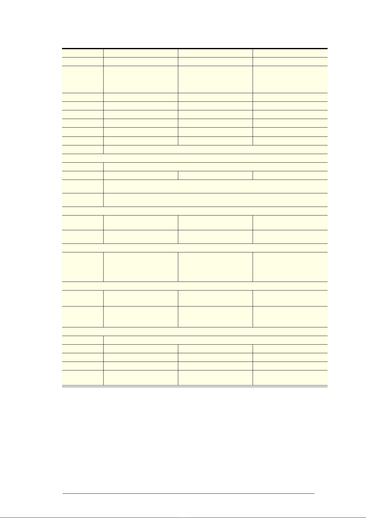
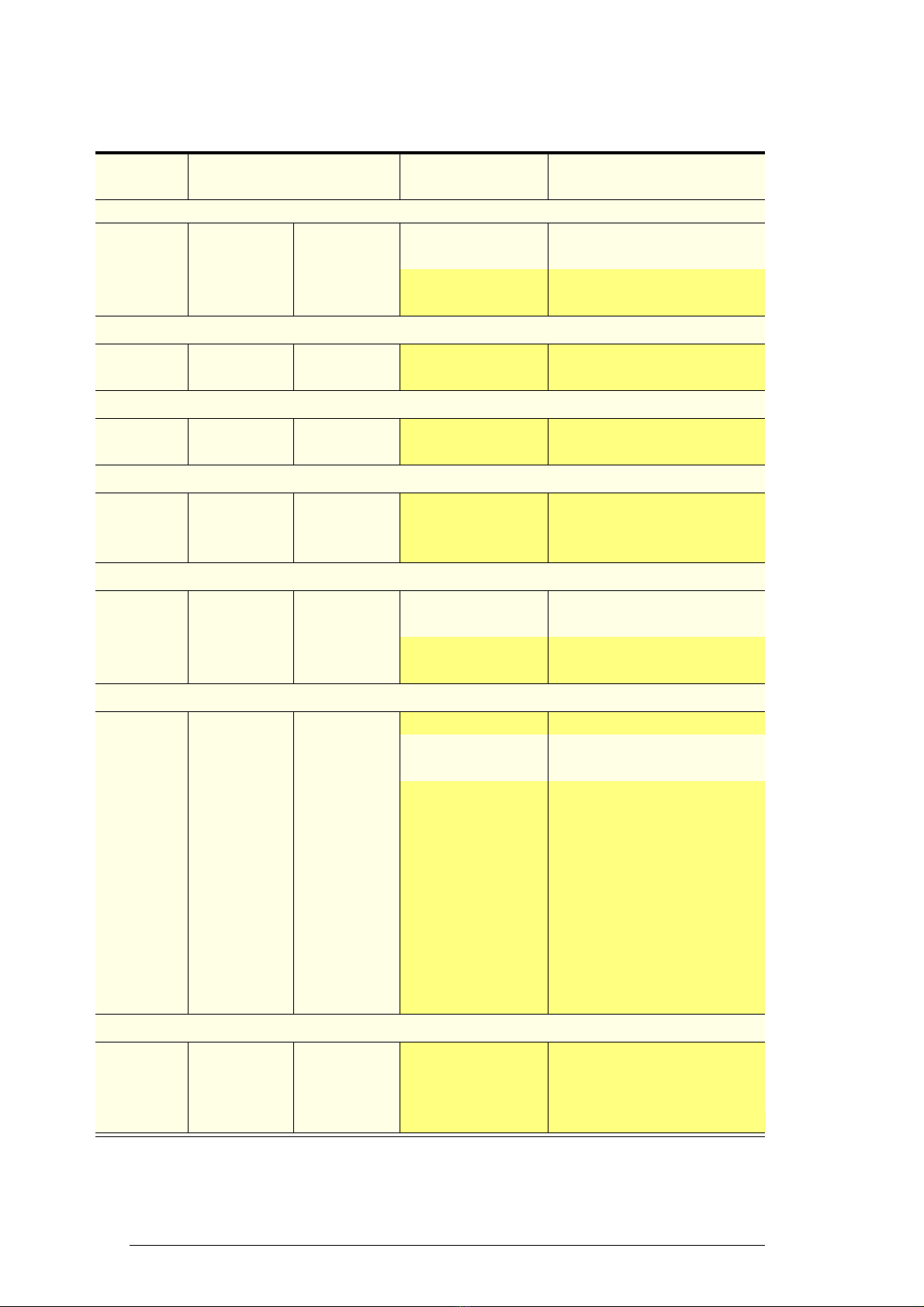
Parameters - Dixell XR30C
Parameters
Display Beverage 160 Food 170 Range Description of Parameter
Set Point Parameters
Set 2 1 LS to US Set Point
Hy 2 2 0.1°C to 25.5°C Differential
LS +1 -1 DO NOT ADJUST
US 15 5
Probe Parameters
Ot -0.7 0DO NOT ADJUST
OE 0 0
Control Parameters
OdS 0 0 DO NOT ADJUST
AC 3 3
Display Parameters
CF °C °C
DO NOT ADJUSTrES dE in
LoD P1 P1
Defrost Parameters
IdF 6 4 1 to 120 hours Interval between defrost cycles
MdF 20 20 0 to 255 minutes Maximum length for defrost
dFd dEF dEF DO NOT ADJUST
dAd 20 20
Alarm Parameters
ALc Ab Ab DO NOT ADJUST
ALU 12 7ALL to 150°C Maximum temperature alarm
ALL -2 -2 -50°C to ALU Minimum temperature alarm
AtH 1 1
DO NOT ADJUST
ALd 240 120
dAO 24 24
tbA n n
PA2 58 58
AU2 65 65
ACH 5 5
dL2 2 2
dA2 0 0
AOP CL CL
Other Parameters
dP1 - -
DO NOT ADJUST
dP2 - -
rEL - -
Ptb - -

15
SKOPE Counterline Series
Electronic Controller
Service Manual
Display Alarms A flashing LED indicates an alarm. The following is a list of the alarm
displays:
Note: Refrigeration system and cabinet lighting shut down with ‘P1’, ‘P2’
and ‘CSd’ alarms.
Alarm Recovery
• Condenser over temperature alarm ‘COH’ recovers when the
condenser is either cleaned or cools down.
• Condenser alarm ‘CSd’ temperature recovers by replugging the cabinet
power supply (or isolation switch). In this case, all the alarms are reset.
Alarm Description
Stage ONE - Maintenance required:
Immediately attend condenser (for auto alarm reset).
Stage TWO - Refrigeration Shut-Down:
Condenser over-temperature has shut-down system and cabinet
lighting. Attend condenser. To reset alarm, cabinet must be
replugged into power supply. For repeat alarms, contact an
authorised service agent.
Faulty Ambient probe (internal cabinet - return air)
Faulty High Temperature probe (condenser)
Internal cabinet - LOW temperature alarm
Internal cabinet - HIGH temperature alarm
16 Electronic Controller
Service Manual
SKOPE Counterline Series
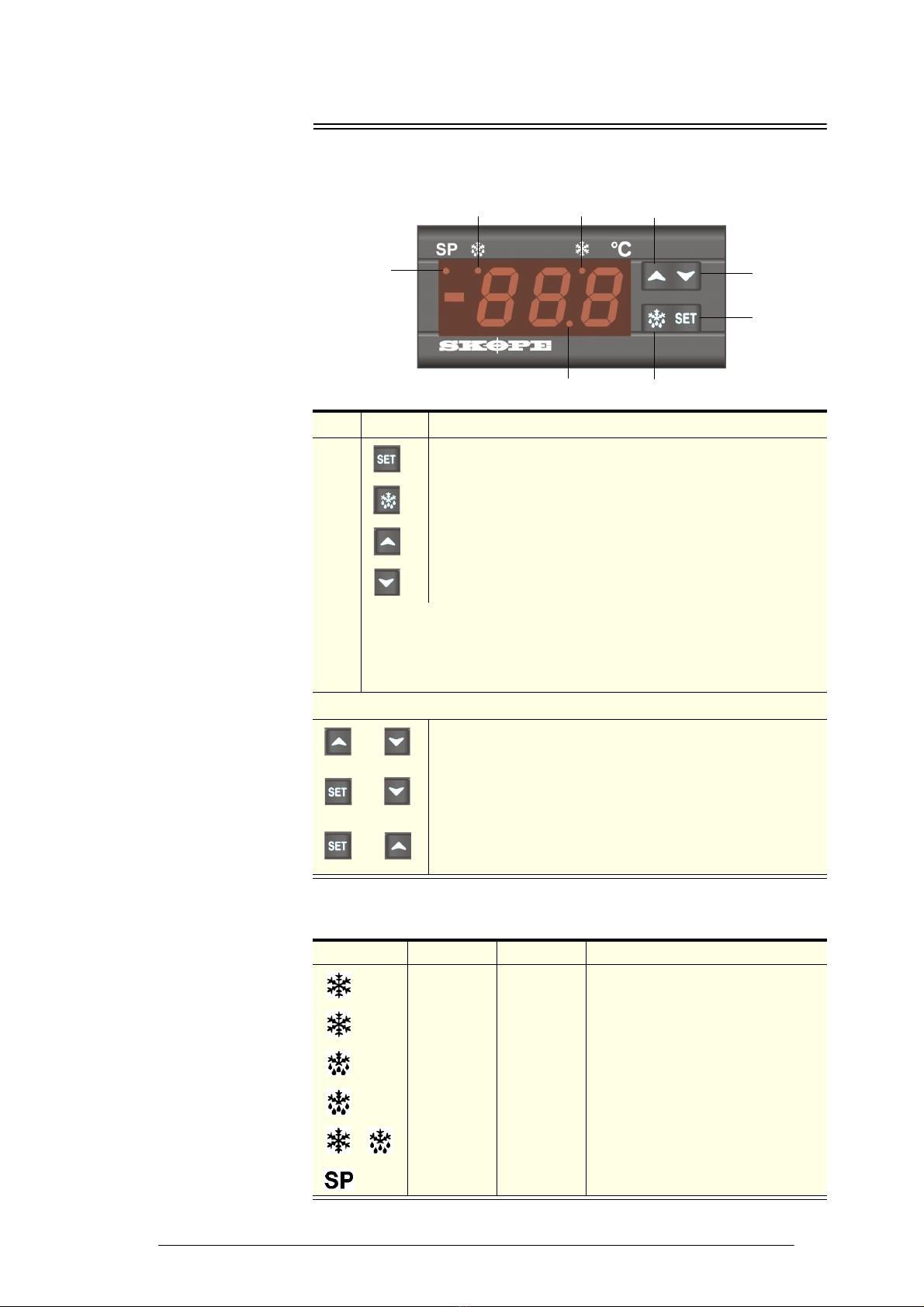
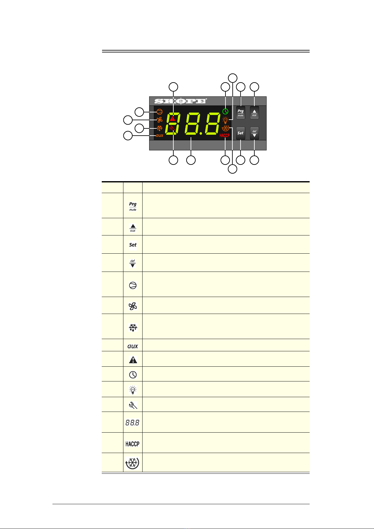
SKOPE CAREL ir33 Controller
Faceplate
Item Icon Function
1
Mute / program: Mutes the audible alarm (buzzer) and
deactivates the alarm relay. To initiate program sets, press for 5
seconds.
2Up: To scroll settings up (in program mode).
3Set point: If pressed for more than 2 seconds displays and / or
enables changing the temperature setpoint.
4Manual defrost / down: Press for more than 5 seconds to initiate
manual defrost. To scroll settings down (in program mode).
5
Compressor: ON when the compressor and condenser fan
starts. Flashes when activation of the compressor is temporarily
delayed.
6Fan: Shows when the fan is operational.
7
Defrost: ON when the defrost is activated. Flashes when the
activation of the defrost is temporarily delayed due to procedures
in progress.
8Aux: n.a.
9Alarm: Flashes in the event of alarms.
10 Clock: n.a.
11 Light: n.a.
12 Service: Flashes in the event of malfunctions.
13 DISPLAY: Shows the cabinet temperature. Flashes when the
door is open.
14 HACCP: n.a.
15 CONTINUOUS CYCLE: On when chiller is running in continuous
run mode.
910
11
12
43
15
14
1312
8
7
6
5
Figure 4: Electronic
controller faceplate
17
SKOPE Counterline Series
Electronic Controller
Service Manual
Defrost Cycle To ensure efficient operation, the electronic controller forces a defrost cycle
every six hours. During a defrost cycle, the compressor stops, DEF and the
will display on the electronic controller faceplate. The chiller will resume
normal operation once the defrost cycle has finished. A manual defrost can
also be initiated by pressing and holding the button.
Continuous
Cycle
The continuous cycle can be used to pull down the temperature of product
inside the chiller quickly. During a continuous cool down the compressor
runs continuously for a set time.
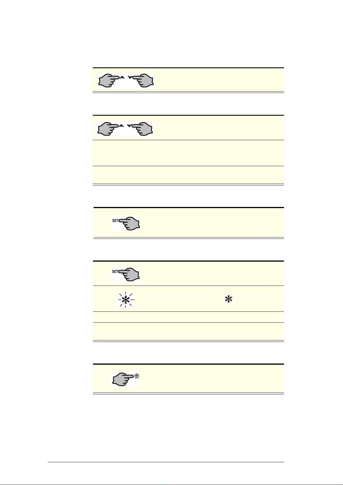
To start a continuous cycle
To stop a continuous cycle
Temperature
Probes Three temperature probes feed data to the electronic controller - the control,
condenser and evaporator probes. Refer to page 51 for information on
servicing the probes.
Control Probe
Used to determine cabinet temperature, temperature display and cabinet
temperature alarms. Located in return airflow on bracket in front of
evaporator face.
Condenser Probe
Used to determine refrigeration shutdown due to overheating of condensing
temperature. Located and insulated on outside middle tube of condenser.
Evaporator Probe
Used to determine defrost termination and evaporator fan activation.
Located inside evaporator coil between fins at bottom of coil.
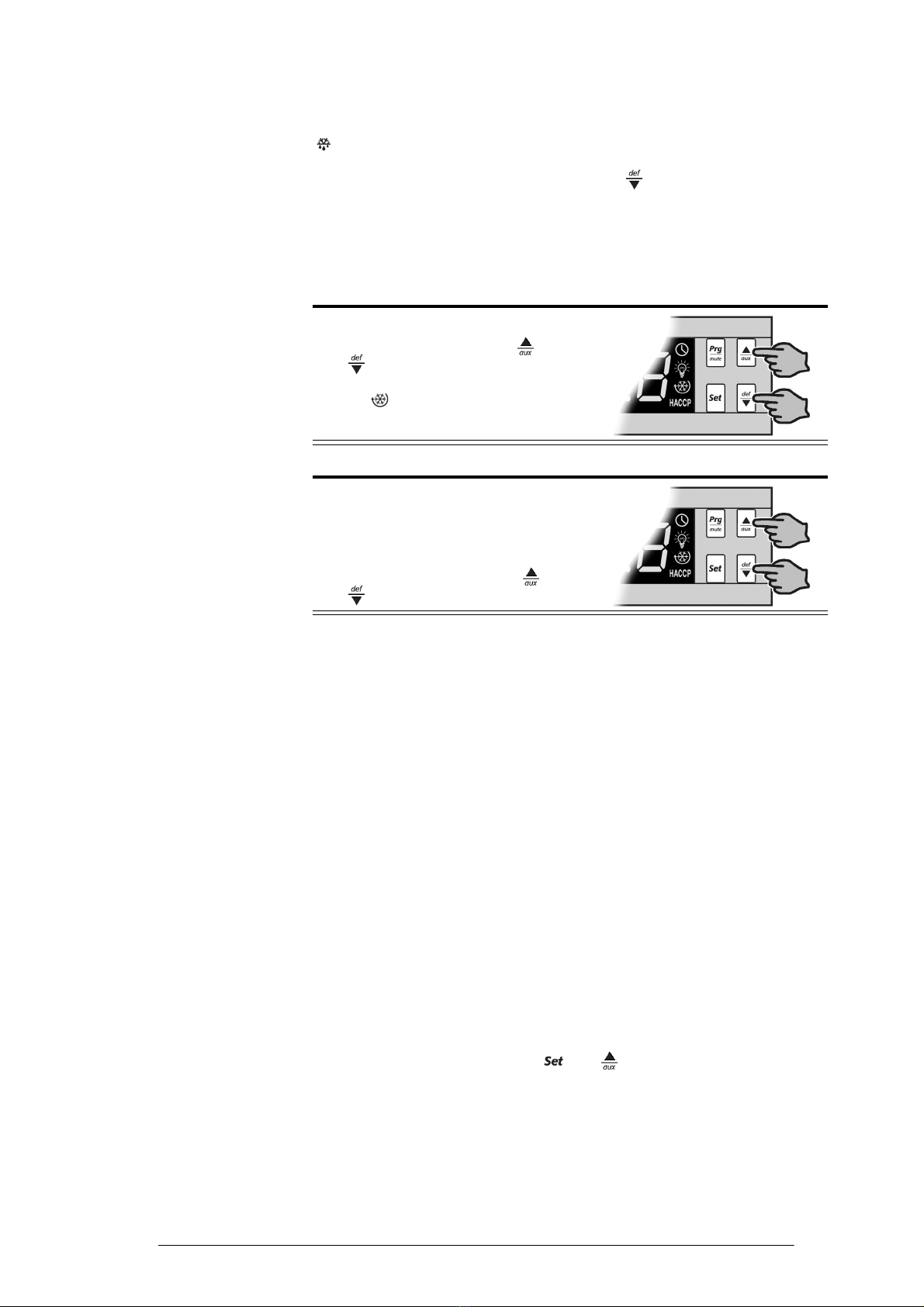
Temperature Probe Reading
The temperature of each of the three temperature probes can be displayed
by pressing and holding both the and keys simultaneously for 5
seconds.
1. While the chiller is switched on and
running, press and hold the and
buttons for five seconds.
The symbol will display during a
continuous cycle.
1. The electronic controller will
automatically stop the continuous cycle
after a period of time.
The continuous cycle can be stopped
by pressing and holding the and
buttons for five seconds.

18 Electronic Controller
Service Manual
SKOPE Counterline Series
To display the temperature probe readings
Temperature probe readings
1. Press and hold both
the and keys simultaneously
for 5 seconds.
2. Press and hold the key to scroll the
probes (see table below). The key
is not active for this function. This
function will time out after 60 seconds
(cannot be turned off prior to 60
seconds elapsed time).
Display Description
P_1 Control probe temperature
P_2 Evaporator probe temperature
P_3 Condenser probe temperature
P_4 Unused
P_5 Unused

19
SKOPE Counterline Series
Electronic Controller
Service Manual
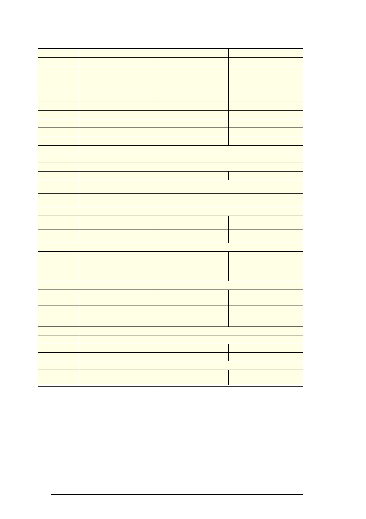
Alarms
The following table explains messages that the electronic controller displays and related alarms.
Alarms signal unexpected operational changes in the chiller and stop when action is taken to
resolve the problem.
Controller alarms
Code Display
Icon
Alarm
Description
Action
Flashing
Product HIGH
temperature alarm
1. Check the cabinet product loading to ensure ventilation slots are not
blocked and that product does not overhang the shelves.
2. Ensure the cabinet is installed with good refrigeration unit ventilation.
3. Check and clean the condenser coil.
4. Unplug cabinet from the power supply for 1 minute, then reconnect to
power supply.
The alarm will automatically reset once the product has returned to
temperature specification.
Flashing
Product LOW
temperature alarm
Refrigeration
system high
temperature
pre-warning (auto
reset)
1. Clean the condenser coil (see page 54).
2. Check refrigeration ventilation. Ensure clear airpath in front of the
cabinet.
3. Ensure the cabinet is installed in a suitable environment.
4. To reset the ‘CHt’ alarm - unplug the cabinet from the power supply for
1 minute, then reconnect to power supply.
If alarm persists:
5. Check that the doors are closing and sealing properly.
6. Check that parameters are set correctly.
7. Check that controller is reading correct condenser temperature.
8. Check that condenser fan and compressor are running correctly.
9. Investigate refrigeration system fault.
Refrigeration
system and cabinet
high temperature
shutdown (manual
reset)
Flashing
Control probe fault 1. Unplug cabinet from the power supply for 1 minute to reset alarm,
then reconnect to power supply.
If alarm persists, work through the following steps until the fault is
resolved:
2. Check probe connection and wiring. If necessary replace probe or
controller.
3. Check probe resistance. If necessary replace probe.
4. Replace controller.
Flashing
Evaporator probe
fault
Flashing
Condenser probe
fault
None Defrost over-time
limit
1. Unplug cabinet from the power supply for 1 minute to reset alarm,
then reconnect to power supply.
2. Check that controller is reading correct evaporator temperature.
3. Check that parameters are set correctly.
4. Check that evaporator fan is operating correctly.
5. If alarm persists, check the product temperature. If too cool, consider
raising setpoint and extending defrost time.
Flashing
Real-time clock
fault
1. Unplug cabinet from the power supply for 1 minute to reset alarm,
then reconnect to power supply.
2. If alarm persists, replace controller.
Flashing
Controller E prom
error
Flashing
Controller E prom
error
None Start defrost
request
None
None End defrost
request
20 Electronic Controller
Service Manual
SKOPE Counterline Series
Programming
Set-Point The chiller is manufactured with a pre-set control temperature set-point of
+1.0°C. If this set-point does not match your required storage temperature
it is recommended that you change the set-point accordingly. The set-point
can be adjusted between a temperature range of 0°C and +3.5°C.
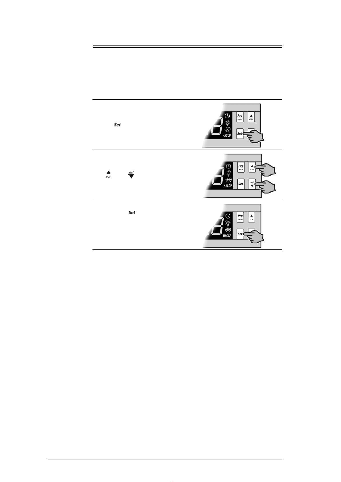
To view and adjust the temperature set-point
1. To view the set-point: press and hold
the key for 2 seconds, until the
set-point value flashes.
2. To adjust the set-point: press either the
and keys to display the
required set-point value.
3. Press the key again to memorise
the new set-point value. If this is not
done within 60 seconds, changes will
be lost and you will need to repeat the
above procedure.
This manual suits for next models
36
Table of contents


