sks 300090 User manual
Installationsanleitung
Installation instructions
SKS-Kinkel Elektronik GmbH
Version: 1.0
Support-Hotline: +49 (0) 2661-98088-112
E-Mail: support@sks-kinkel.de
Dokument Art. Nr. 97009500
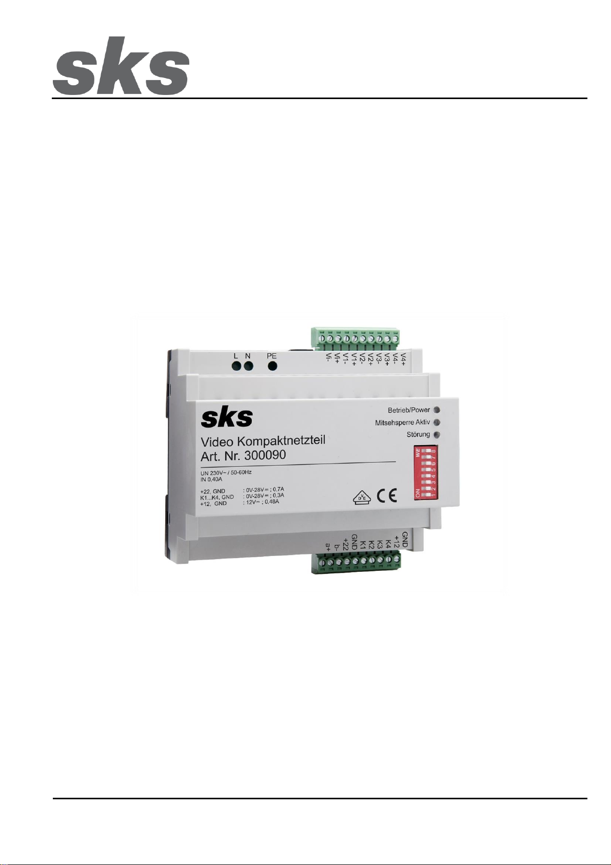
300090 Video Kompaktnetzteil

SKS-Kinkel Elektronik GmbH
DE
300090 Video Kompaktnetzteil
Support-Hotline: +49 (0) 2661-98088-112
- 2 -
Version: 1.0
E-Mail: support@sks-kinkel.de
Dokument Art. Nr. 97009500
1 Installation
Gefahr für Personen durch einen elektrischen Schlag. Verbrennungsgefahr, Geräteschäden und
Fehlfunktionen. Bei der Installation sind die Richtlinien der VDE 0100 und VDE 0800 einzuhalten.
(Deutschland)
Gegenmaßnahmen:
Schalten Sie zu Beginn der Arbeiten alle spannungsführenden Leitungen frei.
Sichern Sie die ausgeschalteten Leitungen gegen irrtümliches Wiedereinschalten.
Stellen Sie Spannungsfreiheit durch Messung fest.
Decken Sie benachbarte, unter Spannung stehende, oder leitfähige Teile ab.
Alle Arbeiten und elektrische Anschlüsse müssen den nationalen Bestimmungen des jeweiligen Landes
entsprechen und von entsprechend ausgebildetem Fachpersonal durchgeführt werden.
Bei Geräten mit 230-V-Anschluss ist die DIN VDE 0100 zu beachten und einzuhalten
1.1 Installationsvorschriften und Schutzmaßnahmen
Das Gerät muss so an die Versorgung angeschlossen werden, dass der Benutzer keinen direkten Zugang zum
Bereich der Netzanschlussklemme hat.
Außerhalb des Gerätes muss eine leicht zugängliche Trennvorrichtung vorhanden sein
Das Gerät entspricht der Überspannungskategorie II
Außerhalb des Gerätes ist eine Überstrom-Schutzeinrichtung vorzuschalten
Das Gerät muss über die Klemme PE an das Schutzleitersystem oder den Schutzpotentialausgleich
angeschlossen werden.
Das Gerät entspricht der Schutzart IP20 und muss in der Endanwendung in einem Verteiler oder Gehäuse auf der
Hutschiene montiert sein.
Das Gerät muss in einem Brandschutzgehäuse nach IEC 60950-1 eingebaut werden.
1.2 Warnhinweis
Eindringen von Flüssigkeiten oder elektrisch leitenden Kleinteilen können einen Kurzschluss, Brand oder
elektrischen Schlag verursachen. Das Gerät darf nicht mit Wasser oder anderen Flüssigkeiten in Berührung
gebracht werden.
Vermeiden Sie das Eindringen von elektrisch leitenden Kleinteilen durch die Lüftungsschlitze
Das Gerät entwickelt im Nennbetrieb Wärme und es ist für eine ausreichende Belüftung zu sorgen. Die
Lüftungsschlitze am Gerät dürfen nicht abgedeckt werden.
SKS-Kinkel Elektronik GmbH
DE
300090 Video Kompaktnetzteil
Support-Hotline: +49 (0) 2661-98088-112
- 3 -
Version: 1.0
E-Mail: support@sks-kinkel.de
Dokument Art. Nr. 97009500
2 Klemmenbezeichnung
Klemme
Bezeichnung
a+ / b-
Eingang Buslinie
+22 / GND
Versorgung Innensprechstelle
K1 / K2 / K3 / K4
Versorgungsspannung Kamera 1 bis 4
+12 / GND
Versorgung Aktivverteiler und Kameraheizung
Vi+ / Vi-
Eingang Videosignal
V1+ / V1-, V2+ / V2-, V3+ / V3-, V4+ / V4-
Ausgänge Videosignal
L / N / PE
Versorgungsspannung
3 Beschreibung
Das Video-Kompaktnetzteil dient zur Versorgung von bis zu 96 Video-Innensprechstellen (ohne Parallelschaltung)
und bis zu 4 Kameramodulen. Es dürfen jedoch maximal 3 Innensprechstellen parallelgeschaltet werden.
Bei einer Parallelschaltung (gleichzeitiges Klingeln mehrerer Sprechstellen) reduziert sich die maximale Anzahl an
Innensprechstellen. Des Weiteren kann nur eine Sprechstelle an einem der 4 Videosignal-Ausgänge ein Videobild
anzeigen.
Der integrierte Aktivverteiler verteilt das Videosignal auf bis zu 4 Steigleitungen. Die Ausgänge und Eingänge sind
symmetrisch aufgebaut und das positive Videosignal (+) darf nicht mit dem negativen Videosignal (-) vertauscht
werden. Jede Steigleitung bzw. jeder Ausgang muss mit einem 75Ohm Abschlusswiderstand versehen werden.
Sind mehr als 4 Steigleitungen vorhanden, können auch externe Aktivverteiler angeschlossen und über das Video-
Kompaktnetzteil versorgt werden. Das Video-Kompaktnetzteil ist kurzschlussfest und vor Überlastung geschützt.
Der fehlerhafte Anschluss der Ein-/Ausgänge ist zu vermeiden. Werden die Signalleitungen des Aktivverteilers (z.B.
V+/ V-) mit den Versorgungsausgängen (z.B. +22) verbunden, kann es zu einer Beschädigung des Video-
Kompaktnetzteiles kommen.
4 LED Anzeige
LED
Bezeichnung
Betrieb / Power
Das Gerät ist betriebsbereit
Mitsehsperre Aktiv
Die Mitsehsperre ist aktiv
Störung
Eine Störung liegt vor

SKS-Kinkel Elektronik GmbH
DE
300090 Video Kompaktnetzteil
Support-Hotline: +49 (0) 2661-98088-112
- 4 -
Version: 1.0
E-Mail: support@sks-kinkel.de
Dokument Art. Nr. 97009500
4.1 Störung- LED
Das Video Kompaktnetzteil 300090 generiert, abhängig von einem aufgetretenen Fehler, einen Fehlercode. Dieser
Fehlercode wird durch die Störung- LED angezeigt.
Bei einem Fehler blinkt die rote LED ca. 1x pro Sekunde. Nachdem die LED in der entsprechenden Anzahl geblickt
hat ist sie für 5 Sekunden aus, bis sie erneut durch Blinken den Fehlercode anzeigt. Die unten dargestellte Tabelle
zeigt den Fehler in Abhängigkeit davon, wie oft die Störung- LED geblinkt hat, an.
LED Blinken
Bedeutung
1x
Min. Eingangsspannung stark unterschritten
2x
Schutz Schalttransistor (+22 Ausgang)
3x
Wärmeabfuhrkapazität überschritten
4x
Gesamtstrom kurzzeitig zu hoch
5x
Gesamtstrom länger zu hoch
6x
Kamera-Ausgang Strom zu hoch
7x
12V-Ausgang Spannung zu niedrig
8x
12V-Ausgang Strom zu hoch
Der letzte erkannte Fehler wird einen Tag lang durch die Störung- LED angezeigt. Wird ein Fehler erkannt, werden
die Ausgänge für 30 Sekunden abgeschaltet. Bei mehrmaligem Auftreten von Fehlern werden die Ausgänge für 6
Minuten abgeschaltet.
4.2 Betrieb / Power LED
Die Betrieb / Power- LED zeigt den Betriebsstatus des Video Kompaktnetzteils 300090 an. Die unten dargestellte
Tabelle zeigt die unterschiedlichen Betriebsstadien an.
Status LED
Bedeutung
LED an
Betriebsbereit
LED blinkt
Versorgungsspannung zu gering
LED aus
Ausgänge abgeschaltet

SKS-Kinkel Elektronik GmbH
DE
300090 Video Kompaktnetzteil
Support-Hotline: +49 (0) 2661-98088-112
- 5 -
Version: 1.0
E-Mail: support@sks-kinkel.de
Dokument Art. Nr. 97009500
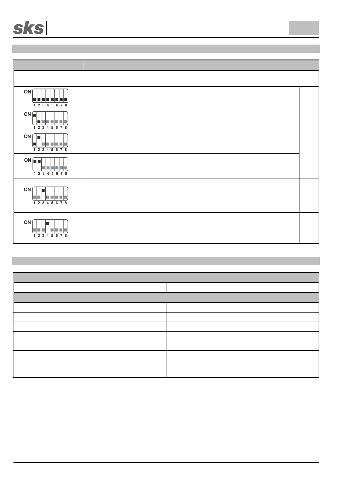
5 DIP- Schalter
DIP- Schalter Position
Funktion / Bedeutung
Für die beschriebenen Funktionen sind jeweils die schwarz hervorgehobenen DIP-Schalter von Bedeutung. Graue DIP-
Schalter haben für die jeweilige Funktion keine Relevanz. Somit ist eine Kombination der Funktionen möglich.
Normalbetrieb
Betriebsart
Stromdetektion mit Kamera 1. Diese Option ist nur in Verbindung mit dem
Türumschalter und für ältere Anlagen nötig. In dieser Betriebsart wird der SKS-BUS (a+ /
b-) nicht benötigt
Nur Busbefehle. Wählen Sie diese Betriebsart, wenn Sie Sprechstellen mit ON-Screen
Menü (z.B. DS2010) in Ihrer Anlage verwenden oder wenn es sich bei der Installation um
eine Neuanlage handelt.
Kamera 1 Dauerversorgung. Wird das Videobild der Kamera für ein
Videoüberwachungssystem genutzt, so muss diese permanent aktiv sein. Die Option ist
nur möglich, wenn nur eine Kamera im System vorhanden ist. Wird die Kamera
dauerversorgt, beträgt die Spannung an +22/GND, 21V
Linienerweiterungsmodus. In Verbindung mit der Linienerweiterung wurde früher das
Videonetzteil 756 benötigt. Das Video Kompaktnetzteil kann auf diese Funktion
umgestellt werden. Somit ist die manuelle Bildholfunktion auf allen Sprechstellen
deaktiviert. Bei Videosprechstellen der DS2010 Serie darf der DIP-Schalter nicht auf ON
gestellt werden
Mit 300020
(4814)
Kompatibilitätsmodus für Sprechstellen vor 2010. Durch die Absenkung wird den
Sprechstellen ein Reset-Befehl anhand kurzer Spannungsabsenkung auf 0V und
anschließender Spannungserhöhung auf 28V mitgeteilt. Die Absenkung muss aktiviert
werden, wenn Sprechstellen des Typs 4505VB, HTV4600 oder il vetro Video in der
Anlage verbaut sind. Wird der DIP-Schalter 4 auf ON gestellt ist die Absenkung
abgeschaltet.
Sprech-
stellen vor
2010
6 Technische Daten
Primärseite
Eingangsnennspannung
207 –253 VAC / 50Hz
Sekundärseite
Ausgangsnennspannung K1 –K4
0 - 28 VDC (+5/-10%)
Ausgangsnennstrom K1 –K4
max. 0,3 A
Ausgangsnennspannung +22 / GND
0 - 28 VDC (+5/-10%)
Ausgangsnennstrom +22 / GND
max. 0,7 A
Ausgangsnennspannung +12 / GND
12 VDC (+5/-10%)
Ausgangsnennstrom +12 / GND
max. 0,48 A
EMV-Norm, Sicherheit-Norm
EMV 2014/30/EU: EN55022 und EN55024, EG
2014/35/EU, EN60950-1

SKS-Kinkel Elektronik GmbH
DE
300090 Video Kompaktnetzteil
Support-Hotline: +49 (0) 2661-98088-112
- 6 -
Version: 1.0
E-Mail: support@sks-kinkel.de
Dokument Art. Nr. 97009500
Allgemeines
Temperatur
-5°C bis +45°C
Feuchtigkeit
20% bis 90% nicht kondensierend
Gehäuse
Kunststoff Hutschienengehäuse
Abmessungen (Breite x Höhe x Tiefe)
105 x 90 x 71 mm (6TE)
Schutzart
IP20
Schutzmaßnahmen
Überspannungs- und Überlastschutz, Strombegrenzung
Netzanschlussklemmen L / N / PE
0,75mm² - 1,5mm², eindrähtig ohne Aderendhülse
0,75mm² - 1,5mm² feindrähtig mit Aderendhülse
Lastklemmen
a+ / b- / +22 /GND / K1 / K2 / K3 / K4 / +12/ Vi+ / Vi- /
V1+ / V1-, V2+ / V2-, V3+ / V3-, V4+ / V4-
0,13mm² - 1,29mm² eindrähtig
0,13mm² - 1,29mm² feindrähtig mit Aderendhülse

SKS-Kinkel Elektronik GmbH
DE
300090 Video Kompaktnetzteil
Support-Hotline: +49 (0) 2661-98088-112
- 7 -
Version: 1.0
E-Mail: support@sks-kinkel.de
Dokument Art. Nr. 97009500
7 Struktur- und Verdrahtungsplan

SKS-Kinkel Elektronik GmbH
DE
300090 Video Kompaktnetzteil
Support-Hotline: +49 (0) 2661-98088-112
- 8 -
Version: 1.0
E-Mail: support@sks-kinkel.de
Dokument Art. Nr. 97009500
8 Service
Für die Gewährleistung gelten die gesetzlichen Bestimmungen (vgl. hierzu auch unsere beigefügten bzw. im Internet unter
www.sks-kinkel.de/agb/ abrufbaren und einsehbaren AGB).
Abwicklung der Gewährleistung
Wir bieten unseren Kunden und auch Elektrofachkräften eine vereinfachte Abwicklung von Gewährleistungsfällen an. Dafür
beachten Sie die Verkaufs- und Lieferbedingungen auf unserer Internetpräsenz oder wenden Sie sich an unsere SKS-Support
Hotline.
Entsorgungshinweis
Durch die separate Sammlung von Elektro- und Elektronikaltgeräten soll die Wiederverwendung, die stoffliche Verwertung bzw.
andere Formen der Verwertung von Altgeräten ermöglicht sowie negative Folgen bei der Entsorgung der in den Geräten
möglicherweise enthaltenen gefährlichen Stoffe auf die Umwelt und die menschliche Gesundheit vermieden werden. Entsorgen
Sie die Verpackungsteile getrennt in Sammelbehältern für Pappe und Papier bzw. Kunststoff.
Die Produkte entsprechen den gesetzlichen Anforderungen, insbesondere dem Elektro- und Elektronikgerätegesetz und der
REACH-Verordnung.
(EU-Richtlinie 2012/19/EU WEEE und 2011/65/EU RoHS).
(EU-REACH-Verordnung und Gesetz zu Durchführung der Verordnung (EG) Nr.1907/2006).
Haftungsausschluss
Wir haben den Inhalt der Druckschrift auf Übereinstimmung mit der beschriebenen Hard- und Software geprüft. Es können
dennoch Abweichungen nicht ausgeschlossen werden, so dass wir für die vollständige Übereinstimmung keine Gewähr
übernehmen. Die Angaben dieser Druckschrift werden regelmäßig überprüft und notwendige Korrekturen sind in den
nachfolgenden Auflagen enthalten.
Service und Support
Unser Supportteam steht Ihnen mit Rat und Tat zur Seite und kümmert sich um Ihre Anliegen. Unser SKS-Support ist für Sie per
E-Mail und Telefon erreichbar. Bitte geben Sie stets eine möglichst genaue Fehlerbeschreibung, Projektbezeichnung, Ihren
Namen und Ihre Kundennummer mit an.
Folgende Möglichkeiten stehen Ihnen zur Verfügung:
SKS-Support Hotline
+49 (0) 2661 98088-112
SKS-Support E-Mail
Wir bieten ausschließlich Support für das Elektro-Handwerk, Architekten und Planungsbüros –Endkunden wenden sich bitte an
Ihren Elektro-Handwerksbetrieb
Anschrift
SKS-Kinkel Elektronik GmbH, Im Industriegebiet 9, 56472 Hof/ Westerwald
Tel.: +49 2661 980 88-0, Fax: +49 2661 980 88 200
E-Mail: info@sks-kinkel.de, www.sks-kinkel.de
Entsorgen Sie das Gerät nicht in den Hausmüll, sondern über eine Sammelstelle für Elektronikschrott. Die
zuständige Sammelstelle erfragen Sie bitte bei Ihrer Stadt- bzw. Kommunalverwaltung.

SKS-Kinkel Elektronik GmbH
EN
300090 Video compact power supply
Support-Hotline: +49 (0) 2661-98088-112
- 9 -
Version: 1.0
E-Mail: support@sks-kinkel.de
Document art. no. 97009500
300090 Video compact power supply
1 Installation
Electrical shock hazard to persons. Danger of burns, damage to device and malfunctions. Observe VDE 0100
and VDE 0800 guidelines during installation. (Germany)
Counter measures:
Before beginning any work, deactivate and disconnect all energized electrical wires.
Secure the switched off/ disconnected lines against erroneous reconnection.
Use a measuring device to make sure that the wires are de energized.
Cover up any adjacent, energized or conducting components.
All work and all electrical connections must comply with the national provisions for the country in question
and must be performed by appropriately trained personnel.
DIN VDE 0100 must be observed and complied with in devices with a 230V connection.
1.1 Installation instructions and protection
The unit must be connected to the power supply that the user has no direct access to the terminal area
Outside the device must be an easily accessible separator
The device complies with overvoltage category II
Außerhalb des Gerätes ist eine Überstrom-Schutzeinrichtung vorzuschalten
Install a fuse in front of the device
The device must be connected to the conductor system or the potential equalization
The device is rated to IP20 protection and it must be mounted on the DIN rail in distribution or plastic housing
The device must be installed in a fire enclosure to IEC 60950-1

SKS-Kinkel Elektronik GmbH
EN
300090 Video compact power supply
Support-Hotline: +49 (0) 2661-98088-112
- 10 -
Version: 1.0
E-Mail: support@sks-kinkel.de
Document art. no. 97009500
1.2 Warning
Penetration of fluids or electrically conductive small parts can cause a short circuit, fire or electric shock. The
device must not be brought into contact with water or other liquids.
Avoid the entry of electrically conductive small parts through the vents
The device generates heat in nominal operation. Provide a adequate ventilation
Do not cover the ventilation slots on the device
2 Terminal designation
Terminal
Designation
a+ / b-
Output busline
+22 / GND
Supply indoor stations
K1 / K2 / K3 / K4
Supply voltage camera 1 to 4
L / N / PE
Supply voltage
+12 / GND
Supply active distributor and camera heating
Vi+ / Vi-
Input video signal
V1+ / V1-, V2+ / V2-, V3+ / V3-, V4+ / V4-
Outputs video signal
3 Description
The video compact power supply provides power up to 96 video indoor stations (without parallel connection) and up
to 4 camera modules. However, a maximum of 3 indoor stations may be connected in parallel.
In a parallel connection (simultaneous ringing of several indoor stations) the maximum number of internal units will
be reduced. In addition, only one station at one of the 4 video signal outputs is able to display a video image.
The active distributor distributes the video signal to up to 4 risers. The outputs and inputs are built symmetrically and
the positive video signal (+) may not be swapped with the negative video signal (-). Every riser and/or every output
must be equipped with a 75Ohm load resistor.
If more than 4 risers are available, external distributor can be connected and powered via the video compact power
supply. The video compact power supply is protected against overload and short circui.
Improper connection of the input / outputs should be avoided. If the video signal lines (e.g. V+/ V-) are accidentally
connected to the supply outputs (e.g. +22), it can result in damage to the video compact power supply.
4 LED display
LED
Designation
Betrieb / Power
The device is ready
Mitsehsperre Aktiv
The privacy function is activated
Störung
Indicates a malfunction
SKS-Kinkel Elektronik GmbH
EN
300090 Video compact power supply
Support-Hotline: +49 (0) 2661-98088-112
- 11 -
Version: 1.0
E-Mail: support@sks-kinkel.de
Document art. no. 97009500
4.1 Störung- LED
Depending on the fault that has occurred, the video compact power supply 300090 will generate a diagnostic error
code. This is indicated by the Störung- LED.
In case of an error the Störung- LED will flash about 1 time per second. Once the LED has lit up the respective
number of times it will stay off for 5 seconds. After that it will come on again and flash accordingly. The table below
shows the number of times the Störung- LED will flash to indicate the respective fault.
LED flashes
Definition
1x
Minimum input voltage not reached by far
2x
Protection switching transistor (+22 Output)
3x
Capacity of heat dissipation exceeded
4x
Total current briefly too high
5x
Total current too high for a longer period
6x
Excess current in camera output
7x
12V-output voltage too low
8x
12V-output excess current
The LED indicates the most recently recognized fault for one day. Once a fault has been detected, the outputs are
shut down for 30 seconds. If a fault occurs repeatedly, there will be a shut-off of 6 minutes.
4.2 Betrieb / Power LED
The Betrieb / Power- LED indicate the operation mode of the video compact power supply 300090. The table below
shows the different stages.
Status LED
Bedeutung
LED on
Operative
LED flashes
Low input voltage
LED off
Outputs switched off
SKS-Kinkel Elektronik GmbH
EN
300090 Video compact power supply
Support-Hotline: +49 (0) 2661-98088-112
- 12 -
Version: 1.0
E-Mail: support@sks-kinkel.de
Document art. no. 97009500
5 DIP- switch
DIP- switch position
Function / meaning
For the described functions the black highlighted DIP switches are respectively important. Grey DIP-switches have no
relevance for the respective function. Therefore, a combination of functions is also possible.
Normal operation
Operating mode
Power detection camera 1. This option is necessary for older devices. The SKS BUS
(a+ / b-) is not required in this operation mode.
BUS commands only. Use this mode if you use indoor stations with an on-screen menu
(e.g. DS2010) or for an entirely new installation.
Camera 1 continuously powered. If the video image of the camera is, for instance, used
for a surveillance system, the camera has to be permanently active. This option is only
available if there is only one camera in the system. Is the camera continuously powered
the voltage at +22/GND will be 21V
Line expansion mode. The video power supply 756 was previously required for the line
extension. Now the video compact power supply may be switched to this function. The
manual picture retrieval function will be deactivated for all indoor stations. For video
indoor stations of the DS2010 series this DIP switch cannot be set to ON.
With 300020
(4814)
Compatibility mode for indoor stations before 2010. By lowering, the output voltage
indoor stations get a reset command. The voltage decreases to 0V and subsequently
increases to 28V. The reduction must be activated, if indoor stations of type 4505VB or il
vetro video are used in the installation. If the DIP-switch was pulled to the ON position,
the reduction is deactivated
Indoor
stations
before 2010
6 Technical data
Primary side
Input rated voltage
207 - 253VAC / 50Hz
Secondary side
Output rated voltage K1 –K4
0 - 28 VDC (+5/-10%)
Output rated current K1 –K4
max. 0,3 A
Output rated voltage +22 / GND
0 - 28 VDC (+5/-10%)
Output rated current +22 / GND
max. 0,7 A
Output rated voltage +12 / GND
12 VDC (+5/-10%)
Output rated current +12 / GND
max. 0,48 A
EMC-standard, safety standard
EMV 2014/30/EU: EN55022 and EN55024, EG
2014/35/EU, EN60950-1

SKS-Kinkel Elektronik GmbH
EN
300090 Video compact power supply
Support-Hotline: +49 (0) 2661-98088-112
- 13 -
Version: 1.0
E-Mail: support@sks-kinkel.de
Document art. no. 97009500
General
Temperature
-5°C up to +45°C
Humidity
20% bis 90% non-condensing
Housing
Plastic top-hat rail housing
Dimensions (width x height x depth)
105 x 90 x 71 mm (6HP)
Type
IP20
Protection measures
Overvoltage and overload protection, current limit
Power input terminal L / N / PE
0.75mm² - 1.5mm², solid without ferrule
0.75mm² - 1.5mm², flexible with ferrule
Load Terminal
a+ / b- / +22 /GND / K1 / K2 / K3 / K4 / +12/ Vi+ / Vi- /
V1+ / V1-, V2+ / V2-, V3+ / V3-, V4+ / V4-
0,13mm² - 1,29mm², solid without ferrule
0,13mm² - 1,29mm², flexible with ferrule

SKS-Kinkel Elektronik GmbH
EN
300090 Video compact power supply
Support-Hotline: +49 (0) 2661-98088-112
- 14 -
Version: 1.0
E-Mail: support@sks-kinkel.de
Document art. no. 97009500
7 Structure- and wiring plan
SKS-Kinkel Elektronik GmbH
EN
300090 Video compact power supply
Support-Hotline: +49 (0) 2661-98088-112
- 15 -
Version: 1.0
E-Mail: support@sks-kinkel.de
Document art. no. 97009500
8 Service
Statutory provisions for warranty shall apply. (See general terms and conditions in the appendix or the internet at www.sks-
kinkel.de/agb/).
Warranty
Our customers and electricians are offered a simplified settlement process of the warranty claim. For more information on this
please refer to the terms and conditions on our internet page or contact the SKS support hotline.
Disposal instructions
By separately disposing of electrical and electronic devices you will allow for the reuse, renewing and recycling of materials and
used appliances and equipment. At the same time this separation shall prevent negative effects of the possibly existing
dangerous substances and materials on the environment and public health. Dispose of the packaging in the respective separate
containers for cardboard, paper and plastics.
The products comply with the regulatory requirement, in particular with electrical and electronic equipment act and the REACH-
regulation.
(EU- guideline 2012/19/EU WEEE and 2011/65/EU RoHS).
(EU-REACH- regulation and the law implementing regulation (EG) Nr.1907/2006).
Liability disclaimer
We have checked the content of this document to verify that it corresponds to the hard- and software described herein. There
may, however, be deviations and SKS-Kinkel GmbH may not be held liable for a lack of conformity. The information in this
document is checked regularly and necessary changes are made in subsequent issues.
Service and support
Our support team provides practical assistance and advice. SKS support may be reached via email or phone. When contacting
us please provide an exact description of the fault, the project name your name and your customer ID.
We provide the following options:
SKS-Support Hotline
+49 (0) 2661 98088-112
SKS-Support E-Mail
Support is exclusively provided for electricians, architects or planning offices. End customers are asked to contact their
electrician.
Address
SKS-Kinkel Elektronik GmbH, Im Industriegebiet 9, 56472 Hof/ Westerwald
Tel.: +49 2661 980 88-0, Fax: +49 2661 980 88 200
E-Mail: info@sks-kinkel.de, www.sks-kinkel.de
Do not dispose of the device with the regular household refuse but take it to a collection point for electronic
scrap. The respective collection point is provided by the municipal administration in the area.

SKS-Kinkel Elektronik GmbH
300090 Video Kompaktnetzteil
Support-Hotline: +49 (0) 2661-98088-112
- 16 -
Version: 1.0
E-Mail: support@sks-kinkel.de
Dokument Art. Nr. 97009500
9 Anhang, appendix
DIP-Schaltereinstellungen für Innensprechstellen, Schaltaktor und TK-Adapter
DIP-Switch settings for intercoms, switch actuator and TK-Adapter
Standard Rufadressbereich Erweiterter Rufadressbereich
Standard call address range Extended call address range

SKS-Kinkel Elektronik GmbH
300090 Video Kompaktnetzteil
Support-Hotline: +49 (0) 2661-98088-112
- 17 -
Version: 1.0
E-Mail: support@sks-kinkel.de
Dokument Art. Nr. 97009500
10 Notizen, notes
Table of contents
Languages:
Other sks Power Supply manuals


Popular Power Supply manuals by other brands


Vertiv
Vertiv NetSure 7100 Compact Installation and user manual

Danfoss
Danfoss VLT Automation Drive FC 300 operating instructions

Altronix
Altronix AL175ULX installation instructions

PCB Piezotronics
PCB Piezotronics 441A101 Installation and operating manual

Nemtek
Nemtek WIZORD 2 Installer manual

Elmdene
Elmdene 20182423N instruction sheet


