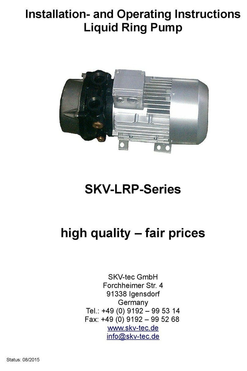
SKV-tec SKV-NS Series User manual

Installation- and Operating Instructions
Side Channel Vacuum Pumps/Compressors
Series SKV-NS / SKV-ND / SKV-NDF
Series SKV-HS / SKV-HD / SKV-HT
High uality – Fair prices
SKV-tec GmbH
Forchheimer Str. 4
91338 Igensdorf
Germany
el.: +49 (0) 9192 – 99 53 14
Fax: +49 (0) 9192 – 99 52 68
www.skv-tec.de
Status: 07/2018

SKV-tec GmbH Operating Instructions
Index
1 Important basic information...................................................................................................................3
1.1 Definition........................................................................................................................................ 3
1.2 Safety instructions..........................................................................................................................3
2 Safety.................................................................................................................................................... 4
2.1 Intended use..................................................................................................................................5
2.2 Potential misuse.............................................................................................................................5
2.3 General safety instructions.............................................................................................................5
2.4 Residual risks................................................................................................................................. 6
3 Design and function............................................................................................................................... 7
3.1 Nameplate......................................................................................................................................7
3.2 Model type (Code).........................................................................................................................7
3.3 Description of the unit....................................................................................................................7
3.4 Design and operating mode of the unit...........................................................................................7
4 ransport, storage and disposal............................................................................................................8
4.1 ransport........................................................................................................................................8
4.2 Storage.......................................................................................................................................... 9
4.3 Preservation................................................................................................................................... 9
4.4 Disposal......................................................................................................................................... 9
5 Installation and connection.................................................................................................................. 10
5.1 Preparation.................................................................................................................................. 10
5.2 Set-up of the unit.......................................................................................................................... 10
5.3 Connecting pipes/flexible pipes....................................................................................................11
5.4 Electrical connection.................................................................................................................... 12
6 Operation............................................................................................................................................. 14
6.1 Preparations prior to commissioning............................................................................................14
6.2 Commissioning............................................................................................................................ 14
6.3 Decommissioning......................................................................................................................... 16
6.4 Recommissioning......................................................................................................................... 16
7 Service and maintenance....................................................................................................................17
7.1 Monitoring of the aggregate.........................................................................................................17
7.2 Cleaning of contaminations..........................................................................................................17
7.3 Replacing the deep groove ball bearings.....................................................................................18
7.4 Service / Support.........................................................................................................................18
7.5 Spare parts.................................................................................................................................. 18
7.6 Disassembly of the unit................................................................................................................ 18
7.7 Assembling of the unit..................................................................................................................19
8 roubleshooting................................................................................................................................... 20
9 echnical Specifications....................................................................................................................... 22
9.1 Operating conditions.................................................................................................................... 22
9.2 General technical data................................................................................................................. 22
10 Appendix............................................................................................................................................ 23
07/2018 SKV-Nx/-Hx-Series 2/30

SKV-tec GmbH Operating Instructions
1 Important basic information
hese operating instructions contains information about
●product description,
●safety,
●transport,
●storage,
●set-up and operation,
●maintenance,
●servicing,
●troubleshooting and
●spare parts
of the side channel blower.
"Handling" of the side channel blower in terms of these
operating instructions are the transport, storage, set-up,
operation, control over operating condition, maintenance,
troubleshooting and servicing of the side channel blower.
Prior to handling of the side channel blower the
responsible staff for operation and servicing have to
completely read and understand the operating
instructions. The operating instructions have to be
strictly adhered to. The operating instructions and all
enclosed documents have to be kept at the place of
installation, always available to personnel.
If there are doubts, please contact the responsible
representation of the SKV-tec GmbH!
1.1 Definition
aggregate complete side channel blower including
pump, power unit and its components
pump side channel blower without power unit
and components
safety valve valve for limiting the generated vacuum
resp. pressure
1.2 Safety instructions
he side channel blower have been designed and
manufactured in accordance with state-of-the-art technology.
Nevertheless by exposure of the side channel blower there
will remain some threats. In these operating instructions we
will refer at suitable points to threats.
Safety instructions are marked with keywords like DANGER,
WARNING, CAUTION or ATTENTION:
DANGER
Risk of personal injuries!
Disregarding this safety instruction leads to
accidents resulting in death or severe
injuries.
WARNING
Risk of personal injuries!
Disregarding this safety instruction can
lead to accidents resulting in death or
severe injuries.
CAUTION
Risk of personal injuries or property
damage!
Disregarding this safety instruction can
lead to accidents with minor injuries or
property damage.
ATTENTION
Risk of hearing loss!
Depending on the size, the unit can emit
sound of high volume.
Depending on the operating state of the
unit can emit sounds in a narrow frequency
band.
During longer stays in the vicinity of a
non-sound-insulated aggregate hearing
protection should be worn.
07/2018 SKV-Nx/-Hx-Series 3/30

SKV-tec GmbH Operating Instructions
2 Safety
he manufacturer is not liable for damages caused by non-
observance of these operating instructions.
WARNING
Risk of death or serious injuries due to
improper use of the unit!
hese operating instructions have to be fully
read and understand prior to any work on the
unit. he operating instructions has to be
strictly adhered to. he operating instructions
and all enclosed documents have to be kept at
the place of installation, always available to
personnel!
Operation of the unit is only permitted to the
purpose indicated under "Intended Use". It has
to be operated at the values indicated under
" echnical data"!
Handling and all work on and with the unit
have to be carried out by qualified personnel!
WARNING
Risk of injury due to working on the unit by
cutting, crushing!
Danger of burns and scalding by contact
with hot surfaces or media!
When handling the unit suitable protective
equipment (safety helmet, shoes and gloves) is
to be worn!
Risk of injury by pulling in and/or
unwrapping of hairs/clothes by moving and
rotating parts!
No loose hair and / or wide, loose clothes!
Wear suitable personal protective
equipment e.g. hairnet!
Danger from rotating parts!
Before operating the unit, it has to be
completely assembled. In particular check the
blower cover, the silencers on the nozzles and
the fan cowl!
Because the impeller is accessible through the
suction / discharge connections, the following
are prohibited:
•Reaching into the unit through open
connections
•Insertion of objects into connections
of the unit
WARNING
Risk due to pressure and vacuum!
Risk caused by escaping media!
Before starting work on the unit:
•At the connections suction and
discharge nozzles conduits were
installed
•hese connections may not blocked,
polluted or closed
•all conduits are tight and have a
sufficient strength
When working on the unit, protective
equipment has to be worn!
All the connections are tested at regular
intervals for strength and tightness!
Risk of injury by the operation of the unit!
When operating the unit the unit must not be
touched nor works are carried out on this!
DANGER
Electrical danger!
Any electrical work has to be performed by a
qualified electrician!
Before starting work on the unit the following
provisions have to be performed:
•Disconnect the unit from the mains
•Ensure the absence of voltage
•Secure against restart
•Earth and short circuit
•Cover and safeguard neighboring live
parts
07/2018 SKV-Nx/-Hx-Series 4/30

SKV-tec GmbH Operating Instructions
2.1 Intended use
•All provisions of this manual, including all safety
instructions have to be observed
•Inspection and maintenance intervals have to be
complied with
•he unit have to be operated exclusively for the
delivery of approved media. It is used for
compressing, conveying and suction of following
approved media:
◦dry air/gases, which are neither explosive,
inflammable, aggressive or toxic
◦Air or air-steam mixtures containing no solids. If
there are small amounts of fine dust a
corresponding filter has to be provided.
he rolling bearings used are sealed on both sides
only with shields. herefore they have to be changed
regularly as instructed in Chapter 7.3!
◦For media with a density greater than air (higher
thermal and mechanical loading on the machine)
the responsible representation of the SKV-
tec GmbH has to be contacted!
•he unit is for continuous operation. For this
purpose, it has to be ensured that waste heat can be
delivered freely to the environment and that a certain
minimum gas flow rate is guaranteed. Furthermore,
frequent switching operations cause an increase of
the temperature of the winding. In case of more
than 5 start-ups of the side channel blower in an
hour (when spread across the hour, even less
when the switching operations happen in a short
time), the responsible representation of the SKV-
tec GmbH has to be consulted!
•he following scenarios have to be avoided:
◦Overheating: he unit must not be operated
above the maximum permissible differential
pressure (see nameplate)! If this danger exists,
a vacuum or pressure relief valve has to be
provided.
◦Motor damage:
he following parameters have to be observed:
the switching frequency of the unit, permissible
fluid and ambient temperatures
(nominal values: Fluid temperature = 15°C,
ambient temperature = 25°C)
he motor protection switch has to be set at the
nominal current as given on the nameplate.
By not respecting the permissible operating
temperatures, the temperature limit of the lubricating
grease of the rolling bearings may be exceeded.
•he unit is intended exclusively for professional use
•he handling of the unit is only permitted by qualified
personnel
Prior to handling of the side channel blower the
responsible staff for operation and servicing have to
completely read and understand the operating
instructions.
If in doubt, please contact the responsible representation
of the SKV-tec GmbH!
2.2 Potential misuse
•he operating limits of the unit concerning pressure,
temperature of the medium, density, viscosity and
velocity have to be observed and complied with
•he permissible density of the conveying medium
has to be respected, otherwise the unit will be
overloaded.
he power consumption of the motor increases with
the density of the conveying medium.
•Avoid sudden changes in the pressure of the
transported gas
•Sudden changes in the temperature of the
transported gas have also to be avoided
•Unauthorized opening of the unit will void any claims
for defects
•If the unit is not approved for the requested use,
operation is prohibited in the following scenarios
◦Operation in rooms where explosive gases may
be present
◦Extracting, delivering or compressing of
explosive, inflammable, aggressive or toxic
media
2.3 General safety instructions
he unit is designed and manufactured according to the state-
of-the-art of technology and the generally acknowledged rules
of safety. Nevertheless through exposure to the unit, danger to
the well-being or even the life of the user or third parties as
well as damage to the unit may occur.
herefore, the following guidelines have to be observed:
•he unit may only be operated in a technically
flawless condition and in compliance with the
regulations, safety precautions and warnings
included in this manual.
•Ensure that this manual and related documents are
complete and readable. In addition, make sure that
the staff has access to these documents at any time.
•Refrain from any operating mode which brings the
staff or third parties at risk
•In case of error which impacts on safety, immediately
shut down the unit and consult the person
responsible for fault diagnosis.
07/2018 SKV-Nx/-Hx-Series 5/30

SKV-tec GmbH Operating Instructions
2.4 Residual risks
WARNING
Risk of injuries from flying parts , which
reach into the openings of the engine
cooling or the coupling guard!
Don't bring in lose parts!
Danger of burns and scalding by contact
with hot surfaces or media!
Do not touch or wear safety gloves!
WARNING
Risk of serious hearing damage due to
noise emissions because of
missing/defective silencers!
Installation/Exchange of the relevant
silencer
Risk of hearing damage!
Depending on the size, the side channel
blower is emitting noise of high volume.
Depending on the operating state the side
channel blower may emit noise in a narrow
frequency band.
For longer stays near a not noise insulated
side channel blower, ear protection should be
worn
07/2018 SKV-Nx/-Hx-Series 6/30

SKV-tec GmbH Operating Instructions
3 Design and function
3.1 Nameplate
1 Product name
2 Serial number
3.2 Model type (Code)
SKV - NS - 50 - 3 - 906
Pump type
Model design
Model size
Number of phase
Engine code
Figure 2: Model-/pump type
Pos Description
a Direction arrow
b erminal box
c Nameplate
d Pressure side (gas outlet)
e Suction side (gas inlet)
Table 1: Legend Figure 3
3.3 Description of the unit
he aggregates are side channel blower for sucking or
compressing air. hey exist in the following designs:
•side channel blowers with one impeller (single-stage)
•side channel blowers with two impellers which differ
in (double-stage)
◦double-stage design (higher pressure
differential)
◦double-flow design (higher flow rate)
•side channel blowers with three impellers
(triple-stage) (very high pressure)
Depending on the design the alignment of the suction/
discharge connections may vary. Details are shown in the
data sheets of the respective aggregate.
he electric motor is modularly connected to the pump unit.
he sealing of the driving shaft is ensured by a maintenance-
free mechanical shaft seal.
3.4 Design and operating mode of the unit
he side channel blower operates according to the principle of
pulse. Kinetic energy is transferred by the rotating impeller to
the medium to be conveyed. his energy is converted into
pressure. he side channel is formed by the specially shaped
housing and the impeller, which is mounted directly on the
motor shaft.
Via the suction connection, the gas is sucked in and
accelerated at the side channel inlet by the rotating impeller in
direction of rotation. By the centrifugal force, the gas is
accelerated radially outwardly deflected by the wall of the side
channel and supplied to the wheel again. With each repetitive
feed into the impeller, the kinetic energy of the gas and hence
the pressure increases. hrough the cross-sectional
constriction at the side channel outlet (breaker), the gas is
ejected from the impeller and leaves the unit through the
pressure connection.
he side channel blower can be used both for generating a
negative pressure (vacuum) as well as for the generation of
positive pressure.
he generated maximum differential pressure of the side
channel blower depends on the power of the associated
engine.
he side channel blower compresses the sucked gas
absolutely oil-free, lubrification of the pump chamber is neither
necessary nor permitted.
he side channel blower is cooled by
•Heat radiation from the surface of the side channel
blower
•the air flow from the external fan of the motor
•the conveyed gas
07/2018 SKV-Nx/-Hx-Series 7/30
Figure 1: Nameplate
Figure 3: parts of the aggregate
a
e
c
d
b

SKV-tec GmbH Operating Instructions
4 Transport, storage and disposal
4.1 Transport
he weight data of the unit has to be observed!
WARNING
Danger from overturning or falling loads!
Before transporting all components have to
be securely mounted. Loose parts have to be
secured accordingly or removed!
CAUTION
Overturning or falling loads can lead to
bruising, fractures, etc.!
Cuts from sharp edges!
Protective equipment has to be worn !
Packaging and inspection:
On delivery, the unit is screwed to a pallet and protected by a
foil and a cardboard box. Unpack the unit and check for
transport damage. ransport damages immediately report to
the responsible representation of the SKV-tec GmbH!
Manual transport by hand:
WARNING
Danger from lifting heavy loads!
he permissible weights for lifting and
carrying of components have to be observed!
•for men max. 30 kg
•for women max. 10 kg
•for pregnant max. 5 kg
Transport with lifting gear:
WARNING
Danger from overturning or falling loads!
he following basic rules have to be
observed when transporting with lifting
equipment:
•the carrying capacity of the lifting gear
has to be at least the weight of the
aggregate
•check the ring lug before each
transport for a tight fit
•he unit has to be secured against
overturning/falling down
•Do not stand under suspended loads
Depending on the model the transport has to be carried out in
different ways:
•the following aggregates up to 30 kg can be
transported by hand:
◦SKV-NS-50 up to SKV-NS-210
◦SKV-ND-88 up to SKV-ND-150
◦SKV-HS-47 up to SKV-HS-120
•all units over 30 kg have to be transported with a
suitable lifting gear by means of a ring lug and/or
straps. hese are the following:
◦SKV-NS-280 to SKV-NS-1370
◦SKV-ND-230 to SKV-ND-1110
◦all SKV-NDF
◦SKV-HS-165, all SKV-HD and -H
his list serves as a general guide line, prior to installation the
operator has to be informed about the weight of the unit. he
weights of the side channel blowers of the normal pressure
and high pressure series can be found in the data sheets of
the respective series.
If the unit is delivered on a pallet, it can be transported
including its package with a hand lift truck / forklift truck.
07/2018 SKV-Nx/-Hx-Series 8/30

SKV-tec GmbH Operating Instructions
4.2 Storage
he units are preserved ex works. his protects the aggregate
for a maximum of three months when properly stored indoors.
he following points have to be observed:
•Seal all openings and connections with appropriate
sealing plugs or screw caps
•he storage room has to be dry, frost-free, vibration-
free and protected. he ambient air must have a
constant temperature with at most +40°C as well as
a constant humidity.
For longer storage periods, poor storage conditions (e.g.
aggressive atmosphere, frequent temperature changes, high
humidity, etc.) or for aggregates which were already in
operation and are going to be stored, the unit has to be
reconserved (see chapter 4.3, “Preservation”).
CAUTION
Risk of material damage due to improper
storage!
he unit have to be stored in accordance with
the guidelines of this manual!
Depending on the storage conditions, sealed rolling bearings
need to be replaced when recommissioning the aggregate:
•Under favorable storage conditions: after 4 years
•Under unfavorable storage conditions (deviating
from the specified storage conditions): after 2 years
4.3 Preservation
CAUTION
Risk of material damage due to improper
storage!
he unit have to be handled in accordance with
the guidelines of these operating instructions
inside and outside with an approved
preservative!
Risk of corrosion due to condensate!
Closures periodically removed so that
accumulated water can escape.
Risk of bearing damage!
Mechanical shocks at standstill and in operation
are to be avoided.
•Seal all openings and connections with appropriate
sealing plugs or screw caps
•Pack the unit in VCI film
VCI stands for "Volatile Corrosion Inhibitor" (volatile
corrosion inhibitor). VCI products (foil, paper,
cardboard, foam) evaporate a substance that
manifests in molecular thickness on the packaged
goods and effectively suppress corrosion on many
metal surfaces by their electrochemical properties.
However, VCI products can attack plastics and
elastomers. Seek advice from your local packaging
dealer! SKV-tec GmbH uses COR EC VCI 126 R
film for the overseas packaging of larger aggregates.
•he storage room have to be dry, frost-free,
vibration-free, protected and have to ensure a
constant humidity
•he motor shaft have to be moved once a month. It
have to be ensured that the position of the motor
shaft and the ball bearings changes.
•Closures periodically removed so that accumulated
water can escape
•For storage periods longer than 6 months all
components made of elastomers (EPDM) have to be
replaced for recommissioning. Components such as
O-rings and shaft seals have to be checked for
elasticity and replaced if necessary.
4.4 Disposal
WARNING
Risks of environmental damage caused by
li uid being pumped!
•Plastic parts have to be removed and
disposed of separately
•Residues of any kind in the aggregate
have to be removed
Assign an authorized company with the
disposal of the unit
07/2018 SKV-Nx/-Hx-Series 9/30

SKV-tec GmbH Operating Instructions
5 Installation and connection
CAUTION
Risk of material damage due to
contamination!
Remove transport locks only immediately
prior to installation of the unit
Remove the transport covers of the
connections just before the installation of the
pipes to the unit
Risk of material damage due to overheating
of the unit!
Set up the unit according to the specified
minimum distances (see chapter 9.2, minimum
distance W ) so that heat dissipation and
cooling air are unimpeded!
Sucking air from other units has to be
avoided!
WARNING
Overturning or falling loads can lead to
bruising, fractures, etc.!
Cuts from sharp edges!
While transporting and installing protective
equipment (safety gloves and safety shoes)
has to be worn!
he unit has to be mounted on a solid
foundation or a fixed acreage. he strength of
the fittings have to be checked regularly!
Danger of tripping and falling !
he unit must not form a tripping hazard!
Danger from flying parts !
Ensure that loose parts are secured and/or
removed!
Provide sufficient safety margin, so that no
persons may be hurt by debris due to a fault in
the external fan!
Risk of burns by hot surfaces and/or hot
media!
During operation the unit must not be touched
because it may result in temperatures above
70°C at the surface!
he installation of the unit has to be executed
in such a way (e.g. perforated plate/wire cover)
that accidental contact is prevented!
Allow to cool after decommissioning!
DANGER
Electrical danger!
•Installation of the unit has to be
performed in such a way that it does
not harm the electrical device
•Supply lines should be routed safety
as cable ducts or in the ground
Any electrical work has to be performed by
a qualified electrician!
5.1 Preparation
he required environmental conditions (see chapter 9.1,
operating conditions) has to be checked
Minimum distances (see chapter 9.2, minimum distance
W ) for heat dissipation has to be observed
he location of the installation must meet the following
conditions:
•he environment of the unit must not be at risk of
explosion
•he unit has to be freely accessible from all sides
•he ambient conditions must comply with the degree
of protection (e.g. IP55) of the drive motor (according
to nameplate)
•he unit has to be set up vibration-free
Only with adequate vibration freedom faultless
operation and a long service life of the equipment is
ensured
5.2 Set-up of the unit
he guidelines from chapter 5.1, „Preparation“ have to be
observed.
Furthermore, the following have to be observed when setting
up the unit :
•has to be carried out on flat surfaces
•he unit can be installed in both horizontal and
vertical axis position. If installed in vertical axis
position, the side channel has to be facing down and
the drive motor up to avoid a heat accumulation.
•on stationary surfaces or structures, it has to be
ensured that this surface is designed for at least the
weight of the aggregate
•the unit has to be secured with the appropriate feet/
mounting plate using suitable fasteners on the
ground
07/2018 SKV-Nx/-Hx-Series 10/30

SKV-tec GmbH Operating Instructions
5.3 Connecting pipes/flexible pipes
Silencers:
he units are supplied by default with silencers for suction
and discharge.
Factory-fitted blind covers must not be removed!
•Normal pressure type
For the single stage design (NS-50 up to NS-1370) and the
double flute design (NDF-500 up to NDF-1940) these
silencers are already mounted on delivery (see Figure 4).
For the double stage design (ND-88 up to ND-1110) the
discharge-side silencer is included loose for packaging-related
reasons. his have to be mounted by the operator in
accordance with Figure 5.
For the double stage design a 90° bend for the pressure-side
silencer is optionally available as an accessory. Using this
bend the pressure-side silencer can be aligned parallel to the
suction silencer.
•High pressure type
For the single stage design (HS-47 up to HS-165) these
silencers are already mounted on delivery (see Figure 4).
For the double and triple stage design (HD-47 up to HD-165
/ H -120 / H -170) the suction-side silencer is included loose
for packaging-related reasons. his have to be mounted by
the operator in accordance with Figure 7.
CAUTION
Risk of material damage due to
contamination!
he interior of the unit has to be free of
contamination!
It has to be prevented that dirt/dust can be
sucked!
If this risk exists, it is necessary to provide a
suitable filter (10 microns or less).
When designing the pipes/hoses the following guidelines
should be observed :
•the suction (vacuum) has to be made via a vacuum-
tight flexible hose or through a decoupled piping
•the pressure release (compression) have to be made
via a pressure-tight flexible hose or through a
decoupled piping
•when using pipes, it is to ensure that no forces are
transferred to the unit and if necessary
compensators have to be used
A fixed piping is not permitted!
•the flow resistance in the pipes/hoses should be kept
as low as possible
•Diameter of the suction/discharge line should be at
least as large as the corresponding connection
diameter on the unit
•sudden changes in cross section have to be avoided
•on the suction side a filter has to be provided against
pollution
•the exhaust air/compressed air line is either
equipped with a continuous gradient, a liquid
separator or a siphon with drain valve so that no
condensate can flow back into the aggregate
When installing the lines ensure the following :
•Before installation all pipes and hydrants have to be
cleaned
•Make sure that no gasket or sealing material (sealing
tape) extends into the interior
•he flanges have to be free of flange lids, plugs
and/or security films
07/2018 SKV-Nx/-Hx-Series 11/30
Figure 4: single stage /
double flute unit NS- /
NDF-)
Figure 5: double stage unit
ND-)
Figure 6: single stage unit
HS-)
Figure 7: double and triple
stage unit HD- / HT-)

SKV-tec GmbH Operating Instructions
Both the suction as well as the discharge connection with the
corresponding silencer is marked by an arrow, that indicates
the direction of conveyance.
Depending on the silencer design (depending on model) and
the selected line type (tube/hose) suction / discharge nozzle
have to be connected differently:
•Silencer with internal thread:
Screw conduit fitting (optional) into the silencer, put
off hose and secure with a hose clamp
•Silencer without internal thread:
Screw hose flange (optional) or conduit fitting
(optional) onto the silencer using the supplied thread
flange, put off hose and secure with a hose clamp
•when connecting to a pipe, it is necessary to
decouple the side channel blower by using a
compensator (e.g. flexible tube)!
In addition following have to be observed in the various
operating modes:
•If, in vacuum operation, the vacuum should be
maintained, even after switching off the unit, a
manually operated or automatic valve (check valve)
in the suction line has to be provided
•Make sure that there are no foreign materials (e.g.
solder) in the suction line
•If there is the risk that the aggregate – valid for
vacuum and pressure operation – operates over a
period of more than a few seconds against a closed
inlet/outlet
Provide a vacuum/pressure limiting valve and set
it to ~90% of the maximum differential pressure
(according to nameplate)
Control of vacuum / pressure:
•In the case of vacuum operation provide venting
valves for the degradation of excess vacuum or for
limiting the flow of air. Do not limit the vacuum or gas
flow through constriction of the suction or
compression line cross-sections.
By conveying bypass air the unit runs cooler and
requires less power.
•In the case of pressure operation provide blow-off
valves to reduce excess pressure or limiting the
airflow. Do not limit the pressure or gas flow through
constriction of the suction or compression line cross-
sections.
By blowing off excess air the unit runs cooler and
requires less power.
5.4 Electrical connection
he electrical connection have to be carried out in accordance
with the following guidelines:
•appropriate VDE or national regulations
•the applicable national, local and system-specific
regulations
•applicable regulations of the utility company at the
location of installation
DANGER
Electrical danger!
Any electrical work have to be performed by a
qualified electrician!
Before starting work on the unit the following
provisions have to be performed:
•Disconnect unit from the mains
•Ensure the absence of voltage
•Secure against restart
•Earth and short circuit
•Cover and safeguard neighboring live
parts
he data on the nameplate of the motor must necessarily
match with the conditions at the set-up place!
Permissible deviations (without reduction in performance):
•± 5% voltage deviation
•± 2% frequency deviation
WARNING
Risk due to pressure and vacuum!
Risk caused by escaping media!
Before starting work on the unit:
•Unit and pipes depressurized
Electrical danger!
erminal box has to be free from:
•foreign bodies
•contamination
•humidity
07/2018 SKV-Nx/-Hx-Series 12/30

SKV-tec GmbH Operating Instructions
he electrical connection has to be made in accordance with
the circuit diagram in the terminal box cover , thereby the
following should be noted:
•Protective earth has to be connected
•erminals have to be used
•Ensure that the connections are safe in the long term
•erminal box cover and cable entries have to be
close to dust and water
he terminal box has to be checked regularly for
leaks
Wiring diagram AC motor:
•Connection with 1 capacitor (230 V):
See cover of the terminal box (left & center: the
capacitor / right & center: the supply voltage)
•Connection with 2 capacitors (115 V / 230 V):
Wiring diagram three-phase motor:
•Delta connection (low voltage):
•Star connection (high voltage):
According to standard EN 60204-1 chapter 7.3 an aggregate
with a rated power of more than 0.5 kW has to be protected
against inadmissible heating. he use of a motor protection
switch protects the motor against overload as well as a short
circuit. his motor protection switch has to be set to the
nominal current indicated on the nameplate of the motor.
CAUTION
Risk of material damage due to incorrect
direction of rotation!
An operation in the wrong direction of rotation
can damage the aggregate in a short time
Before starting up the unit check for correct
direction of rotation!
Check polarity of the electrical connection
(if necessary swap two phases)!
Check for correct direction of rotation:
•Determine the intended direction of rotation by
means of the glued/molded arrow
•urn on the driving motor for a split second
•Determine the direction of rotation by means of the
external fan wheel shortly before the standstill
If the direction of rotation is wrong swap any two
phases (three-phase motor)
Operation with fre uency converter (FC):
WARNING
Units with UL approval in the United States
may not be operated on frequency converters
without testing by an appropriate inspection!
he following have to be observed for operation with
frequency converter:
•Depending on the design of the frequency converter
electromagnetic emissions may occur, which arise
from high-frequency current and voltage harmonics
in the motor supply cables
•EMC instructions of the frequency converter
manufacturer have to be observed!
•Use shielded cables and connect the shield over a
large area to the metal terminal box conductively with
a metal screw
•Each motor is equipped with a BMS (BiMetalSwitch),
which can be connected to the thermistor input of the
FC through two wires (in the terminal box)
•Limits of the frequency have to be maintained (see
nameplate)
•he maximum inverter input voltage is 460V
07/2018 SKV-Nx/-Hx-Series 13/30

SKV-tec GmbH Operating Instructions
6 Operation
WARNING
Risk due to pressure and vacuum!
Risk caused by escaping media!
Before operating the unit the following
conditions have to be met:
•At the connections suction and
pressure lines were installed
•All lines are tight and have a sufficient
strength
•All lines must not be closed, blocked
or dirty
When working on the unit protective
equipment has to be worn!
Danger from rotating parts!
Before operating the unit the blower cover, the
silencers on the suction/discharge nozzle and
the fan cowl have to be installed!
Risk of injury from the operation of the unit!
When operating the unit the following has to be
avoided:
•o touch the aggregate
•Performing works on aggregate
DANGER
Electrical danger!
Any electrical work has to be performed by a
qualified electrician!
Before starting work on the unit the following
provisions have to be performed:
•Disconnect unit from the mains
•Ensure the absence of voltage
•Secure against restart
•Earth and short circuit
•Cover and safeguard neighboring live
parts
6.1 Preparations prior to commissioning
Identification of the unit model by the nameplate
(see chapter 3.1, page 7)
For treated and/or stored aggregates the seals have to be
removed (see chapter 4.3, page 9)
Determination / verification of downtime
•for downtime over a year the manufacturer have to
be contacted for necessary steps
•for a downtime of less than one year the prescribed
steps (see chapter 6.2, commissioning) have to be
performed
6.2 Commissioning
Start up:
CAUTION
Risk of material damage due to overload!
A suction-side shut-off valve has to be fully
open. hrottling on the suction side is
prohibited!
A pressure-side shut-off valve is to open.
The unit must not be operated with closed
shut-off valve!
he operating limits (see chapter 9.1, page 22)
of the unit have to be observed.
he following have to be checked before the first start-up:
•ightness of the piping and hose connections
•Direction of rotation
•Correct electrical connection of the motor
Set motor protection switch to the specified nominal
current!
•he values given on the unit (nameplate) have to be
observed!
•he unit is prepared
Then continue with the following steps:
•Open the suction-/pressure-side fitting
The unit must not be operated with closed shut-
off valve!
•urning on the engine
Shutdown:
•Shutting down the motor
•Close the suction-/pressure-side shut-off valve
•repeat checking for leaks of the lines, the unit and
the fittings
07/2018 SKV-Nx/-Hx-Series 14/30

SKV-tec GmbH Operating Instructions
Verification of operating speed:
he operating speed indicated on the nameplate of the unit
has to be observed and adhered to.
Exceeding the nominal speed deteriorates noise radiation,
vibration behavior, service life of the bearing grease and
therefore the bearing replacement intervals.
WARNING
Risk of serious hearing damage due to
noise radiation because of missing /
defective silencers!
he actual noise emission during operation
may vary from the measured noise emission
values of the manufacturer, as they are highly
dependent on installation and system
conditions.
herefore carry out an acoustic emission
measurement after installing the unit and if
necessary following steps shall be taken:
•Noise area marked with warning sign
•Wear hearing protection
•When air is freely sucked or blown-off
from ambient additional silencers
have to be provided
Risk of hearing damage!
Depending on the size, the side channel
blower is emitting noise of high volume.
Depending on the operating state the side
channel blower may emit noise in a narrow
frequency band.
For longer stays in the vicinity of a non
noise insulated side channel blower ear
protection should be worn!
WARNING
Risk of burns by hot surfaces and/or hot
media!
In operation the unit must not be touched
because it may result in temperatures above
70°C at the surface!
he installation of the unit has to be executed
in such a way (e.g. perforated plate/wire cover)
that accidental contact is prevented!
Allow to cool after decommissioning!
CAUTION
Risk of corrosion due to condensate!
Remove closures periodically, so that
accumulated water can escape.
Risk of bearing damage!
Mechanical shocks at standstill and in operation
are to be avoided.
07/2018 SKV-Nx/-Hx-Series 15/30
SKV-tec GmbH Operating Instructions
6.3 Decommissioning
DANGER
Electrical danger!
he electrical connection has to be performed
by qualified electricians!
Before starting work on the unit following actions
have to be performed:
•Disconnect unit from the mains
•Ensure the absence of voltage
•Secure against restarting
•Earth and short circuit
•Cover and safeguard neighboring live
parts
WARNING
Risk due to pressure and vacuum!
Risk caused by escaping media!
Before starting work on the unit:
•Unit and pipes depressurized
When working on the unit protective
equipment has to be worn!
Escaping fluids have to be collected and
disposed of in accordance with the guidelines!
he following provisions have to be performed if the pump /
unit is taken out of operation or shut down:
•If the unit is shut down but will remain operational:
Once a month, put the unit briefly (5-10 minutes)
into operation
•If the unit is taken out of operation:
◦Shut down unit
◦Close shut-off valves on the suction / discharge
connections and relief pressure
•If the unit is dismantled:
◦ake unit from the mains and secure it against
unauthorized activation
◦Dismantle pipes / hoses
◦Close all connections / fittings
•If the unit is decommissioned for an extended period
or stored, the appropriate actions (see chapter 4.2,
page 9) have to be performed
6.4 Recommissioning
For longer storage of more than one year, all the steps of
commissioning – as described in chapter 6.1, „Preparations
prior to commissioning“ and chapter 6.2, „Commissioning“ –
have to be performed.
Depending on the length of storage and the storage
conditions the applied sealed rolling bearings need to be
replaced when recommissioning the aggregate:
•Under favorable storage conditions: 4 years
•under unfavorable storage conditions (as specified
above): 2 years
Further information on storage conditions can be found in
chapter 4.2.
After a long downtime the insulation resistance of the motor
should also be measured and checked. he motor winding is
too wet for values of less than 1 kOhm per volt of rated
voltage and have to be dried.
If the unit is temporarily turned off and supposed to remain
ready for operation, it is sufficient, if the unit is operated once
a week.
07/2018 SKV-Nx/-Hx-Series 16/30

SKV-tec GmbH Operating Instructions
7 Service and maintenance
DANGER
Electrical danger!
he electrical connection has to be performed
by qualified electricians!
Before starting work on the unit the following
actions have to be performed:
•Disconnect unit from the mains
•Ensure the absence of voltage
•Secure against restarting
•Earth and short circuit
•Cover and safeguard neighboring live
parts
WARNING
Risk due to pressure and vacuum!
Risk caused by escaping media!
Before starting work on the unit:
•Unit and pipes depressurized
When working on the unit protective
equipment has to be worn!
WARNING
Danger from rotating external fan!
he fan cover must not be dismantled!
Danger from rotating impeller of the unit!
Before starting work on the unit, the unit has to
be taken out of service and the impeller
completely stopped!
WARNING
Danger of burns from hot surfaces and / or
hot fluids!
In operation, the unit must not be touched!
Allow to cool after decommissioning!
CAUTION
Overturning or falling loads can lead to
bruising, fractures, etc.!
Cuts from sharp edges!
While transporting and handling the unit
protective equipment has to be worn!
7.1 Monitoring of the aggregate
he following points have to be checked at regular intervals:
•Compliance with the maximum permissible
vacuum/compression pressure and the permitted
volume values
•Contamination of the motor and the filter
•Conspicuous running noise of the ball bearings
•Current consumption of the motor
For trouble-free operation pay attention to:
•ightness of the connections and the aggregate
•Intact and clean filter
•No overload
•No unusual running noises or vibrations
7.2 Cleaning of contaminations
he unit is largely maintenance- free but – depending on the
installation site – it has to be cleaned at regular intervals.
herefore, following actions have to be performed regularly:
•o remove volatile residues purge the aggregate with
air and return it to outside pressure
•Periodically remove dirt, which is in the cooling fins,
the external fan and the fan cowl of the motor.
Clean using compressed air
•Depending on the dust at the installation site the
filters are regularly
◦to clean with compressed air
◦or if necessary to replace completely
07/2018 SKV-Nx/-Hx-Series 17/30
SKV-tec GmbH Operating Instructions
7.3 Replacing the deep groove ball bearings
he bearings used are sealed on both sides only with shields.
herefore they have to be changed according to this capital in
the following intervals!
If the unit is operated according to its intended use (see
chapter 2.1), in compliance with the operating conditions (see
chapter 9.1) and according to the specific type plate, the
rolling bearings have to be replaced every 2 years.
Generally both the motor-side and the compressor-side
(impeller-side) deep groove ball bearings have to be replaced
in this interval.
Instructions for disassembling and disassembling the unit can
be found below in Chapter 7.6 and 7.7.
he following scenarios lead among others to a shortening of
the change interval:
•Operation with insufficient filtering
•Overload and overheating of the unit
•Exceeding the permissible switch-on processes
•Pumping of unsuitable media
•Insufficient decoupling (low vibration) of the unit
•Inadmissible operating conditions
7.4 Service / Support
For maintenance and repair work, please contact our service.
When returning the unit the following have to be observed:
•Unit has to be cleaned inside and outside
(see chapter 7.2, page 17)
•Unit must not be disassembled and has to be
supplied with all the necessary parts
•he identification of the unit on the nameplate has to
be readable
•Any returning aggregate has to be accompanied by a
duly completed "Declaration of Harmlessness"
•For returning the original packaging should be used
7.5 Spare parts
As spare parts, only the rolling bearings and seals are
provided (see Figure 8, page 23). If other parts are necessary
for the maintenance, contact your responsible representative
of the SKV-tec GmbH to determine, whether a repair is
economically or whether a replacement should be considered.
When ordering spare parts and accessories the following
information is required:
•Complete model code of the unit using the
nameplate (see chapter 3.1, page 7)
•Serial number (S/N) of the aggregate
(see chapter 3.1, page 7)
•Position and parts designation
Commercially available standard parts can be purchased in
free trade.
7.6 Disassembly of the unit
DANGER
Electrical danger!
he electrical connection has to be performed
by qualified electricians!
Before starting work on the unit the following
actions have to be performed:
•Disconnect unit from the mains
•Ensure the absence of voltage
•Secure against restarting
•Earth and short circuit
•Cover and safeguard neighboring live
parts
WARNING
Risk of injuries when the engine is running!
During operation the unit must not be touched!
During operation, no work may be performed
on the unit!
Risk due to pressure and vacuum!
Risk caused by escaping media!
Before starting work on the unit, the unit and
the lines have to be depressurized
07/2018 SKV-Nx/-Hx-Series 18/30

SKV-tec GmbH Operating Instructions
Before disassembly work on the unit the following conditions
have to be met:
•he safety instructions have to be observed
•he unit is shut down and disconnected from the
mains
•Connected pipes / hoses and equipment such as
separators, pressure gauge, etc. are disassembled
•he unit has been removed from the system and is
on a clean, flat assembly area
Disassembling the impeller-side rolling bearing:
(1) Disassembling blower cover
◦Put the aggregate on the fan bowl
◦Loosen and remove the screws of the blower
cover
◦Loosen and remove the screws of the bearing
cover
◦Removal of the blower cover
The plane surfaces of the blower
cover/housing must not be damaged!
(2) Disassembling bearing cover
◦Loosen and remove the screw and washer of
the shaft lock
◦Pull the bearing cover including bearing using a
suitable detaching device from the motor shaft
◦Press bearing out of the bearing cover
Disassembling the motor-side rolling bearing:
•Set up unit horizontally
•Remove the fan cowl
•Loosen and pull off the external fan from the motor
shaft, if necessary remove retaining ring
•Loosen the screws of the end shield and remove the
end shield
•Pulling off the rolling bearing of the motor shaft
7.7 Assembling of the unit
CAUTION
Risk of material damage due to improper
assembly!
Assemble the unit according to the
guidelines for engineering!
Use only original parts!
Carry out the assembly on a clean, level
assembly area!
Furthermore, please note the following:
•Worn parts have to be replaced by original Spare
Parts
•Use only functional and tested parts
•Seals generally have to be replaced
•All parts have to be cleaned
•he necessary tightening torques are to be observed
Assembling the impeller-side rolling bearing:
(1) Assembling of the bearing cover
◦Put the aggregate on the fan cowl
◦Press bearing into the bearing cover
◦Press the bearing cover including bearing using
a suitable attaching device on the motor shaft
◦Reattach the screw and washer of the shaft lock
(2) Assembling of the blower cover
◦Align the blower cover on the blower housing,
paying attention to the orientation of the bearing
cover
◦ightly coil the bearing cover on the blower
cover
◦ightly coil the blower cover on the blower
housing
Assembling the motor-side bearing
•Set up unit horizontally
•Pressing the rolling bearing on the motor shaft
•Align the end shield and screw it to the motor
housing
•Press the external fan on the motor shaft
•Reassembly of the fan cowl
07/2018 SKV-Nx/-Hx-Series 19/30

SKV-tec GmbH Operating Instructions
8 Troubleshooting
DANGER
Electrical danger!
he electrical connection has to be performed
by qualified electricians!
Before starting work on the unit the following
actions have to be performed:
•Disconnect unit from the mains
•Ensure the absence of voltage
•Secure against restarting
•Earth and short circuit
•Cover and safeguard neighboring live
parts
WARNING
Risk of injuries when the engine is running!
During operation the unit must not be touched!
During operation, no work may be performed
on the unit!
Risk due to pressure and vacuum!
Risk caused by escaping media!
Before starting work on the unit, the unit and
the lines have to be depressurized
If the operator of the unit can not resolve the disturbance, the contact person responsible for the maintenance of the unit is to be
contacted.
If the problem can not be resolved, contact your responsible representation of the SKV-tec GmbH!
Defect Cause Rectification
Engine will not start
(no running noise)
At least two phases of the power supply are
interrupted
Check the power supply and eliminate interruption
One phase of the power supply is
interrupted
Check the power supply and eliminate interruption
Motor protection switch has triggered Check the motor and switch on protection switch again
Motor blocked Check the motor
Engine does not start
(humming noise)
Impeller is stuck Open blower cover, remove foreign material and clean
side channel (see chapter 7.2, page 17)
If necessary check or correct impeller gap
Contamination of the pump Clean the aggregate (see chapter 7.2, page 17)
defective impeller Replace impeller (service)
Defective motor bearings Replace motor bearings
Motor protection
switch triggers
Short circuit in the motor winding Check the motor winding
Incorrect setting of the motor protection
switch
Check settings, if necessary, replace the motor
protection switch
Excessive back pressure in the pressure
side connection
Reduce back pressure if necessary clean filters and
periphery
Blocked / Plugged suction side Open / freely accessible suction side
Motor / pump blocked See "Engine does not start"
07/2018 SKV-Nx/-Hx-Series 20/30
This manual suits for next models
25
Table of contents
Other SKV-tec Water Pump manuals
Popular Water Pump manuals by other brands

Sandpiper
Sandpiper HDF2-A Service and operating manual

NUK
NUK Expressive 62772 operating instructions

Coopers of Stortford
Coopers of Stortford L476 Instructions for use

Pioneer
Pioneer APPLI-PRO DASIC manual

Standard Pump
Standard Pump SP-PP Series Operating instructions and parts manual

Crane
Crane 3SHV Installation and operation manual