ALPHA WORKS HPT50 User manual

ALPHAWORKS
WATER PUMP
OPERATOR' MANUAL

PREFACE
1. Thank you for choosing a water pump of AlphaWORKS.
2. Please keep the owner’s manual for reference.
3. This manual should be considered a permanent part of the water pump.
4. The manual instructs the user how to operate the water pump including and
be sure to read it carefully first before operation to get the best results. If a
problem should arise or if you have any questions about the pump, please
contact our AlphaWORKS customer service by 1-866-493-0524 for
assistance.

CONTENTS
1. SAFETY ………………………………………………..............................................………….… 1
2. COMPONENT IDENTIFICATION …………………………………………………….…………… 3
3. CONTROL SYSTEM …………………………………………………………………...…………… 4
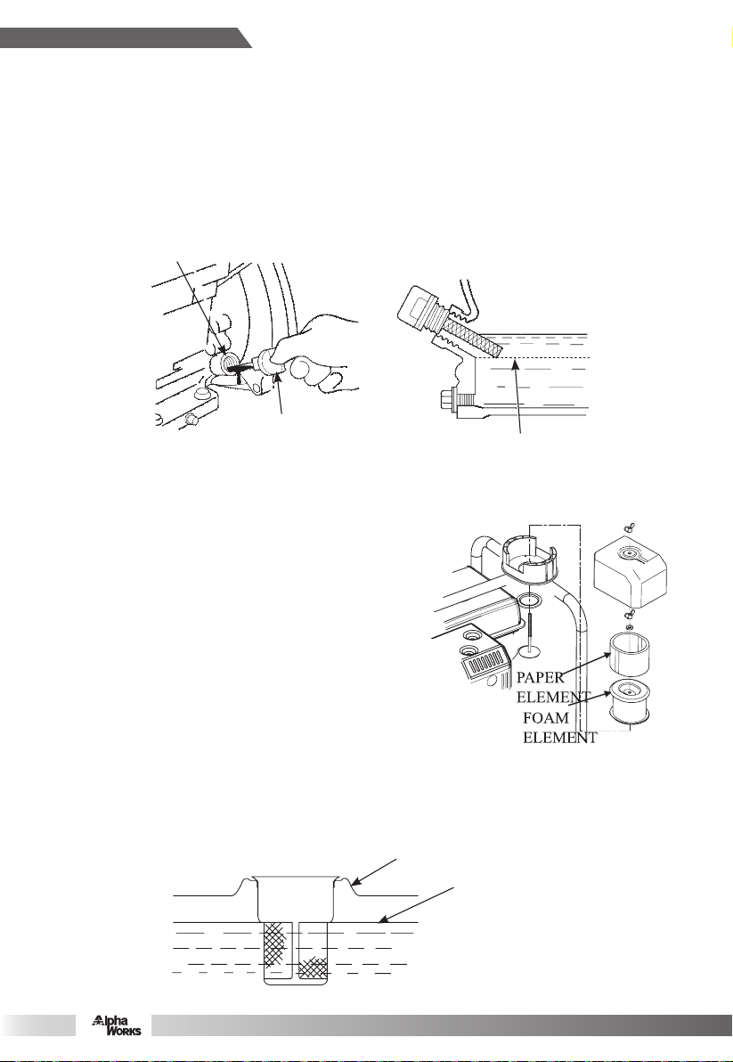
4. PRE-OPERATION INSPECTION ……………………………………………….………………… 5
5. OPERATION ………………………………………………………………………………………… 7
6. STARTING THE ENGINE ………………………………………………………………………..… 9
7. STOPPING THE ENGINE ………………………………………………………………………… 11
8. MAINTENANCE …………………………………………………………………………………… 11
9. STORAGE ………………………………………………………………...……………………… 14
10. TROUBLESHOOTING ……………………………………………………………...…………… 15
11. ELECTRIC DIAGRAM ……………………………………......…………………………….…… 18
12. SPECIFICATION ……………………………………………………………………….…………19
SAFETY
Our company's water pump is designed to give safe and reliable service if operated according
to instructions. Read and understand the Owner’s Manual before operating the water pump.
Failure to do so could result in personal injury or equipment damage.
Safety Messages
Your safety and the safety of others are very important. We have provided important safety
messages in this manual and on water pump and engine.
Please read these messages carefully.
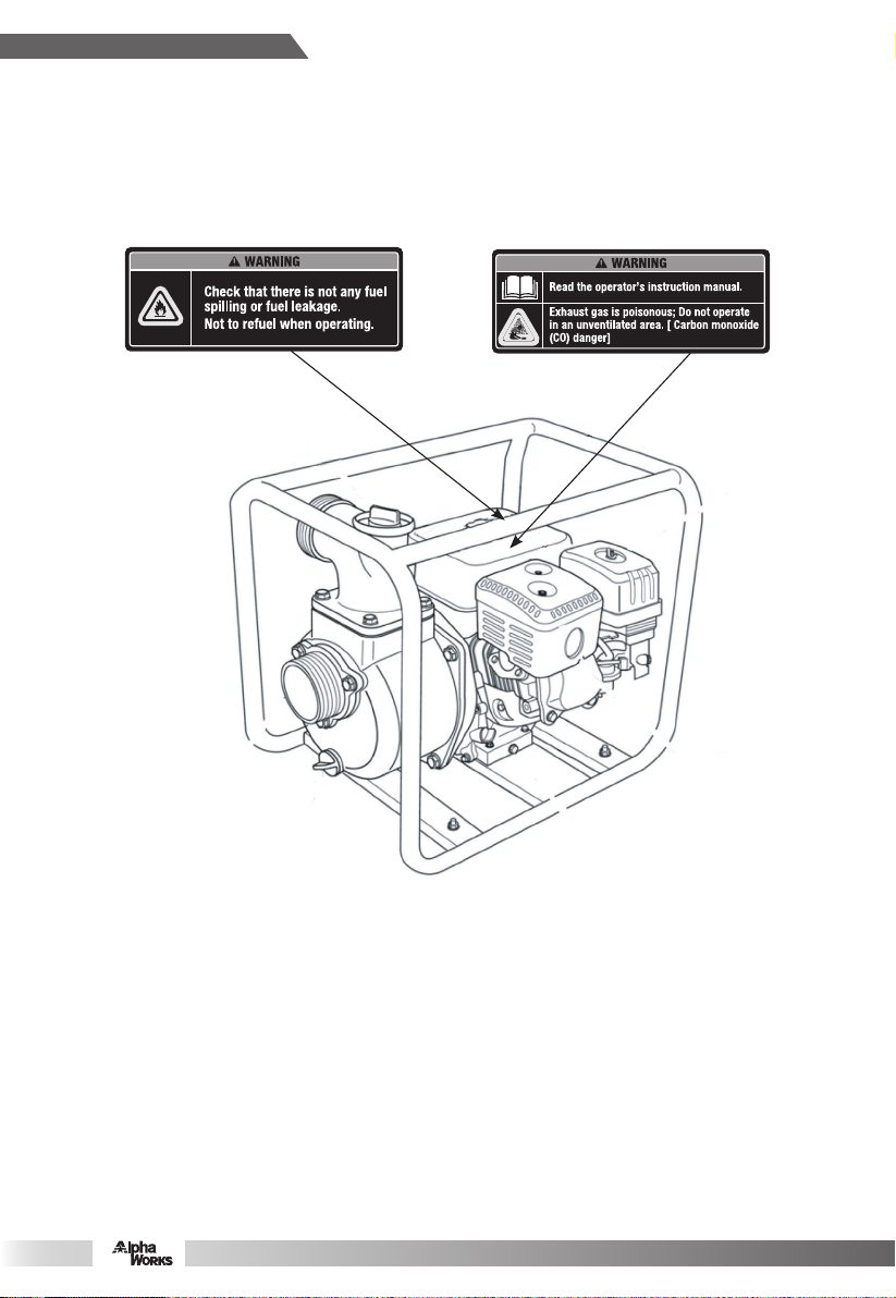
Safety label - on the water pump and engine.
A safety message - alerts you to potential hazards that could hurt you or others. Each safety
message is preceded by a safety alert symbol and one of three words: WARNING, CAUTION,
or NOTICE. These mean:
You CAN be KILLED or SERIOUSLY HURT if you don’t follow instructions.
You CAN be HURT if you don’t follow instructions.
NOTICE: Your water pump or other property could be damaged if you don’t follow instructions.
Safety Instruction
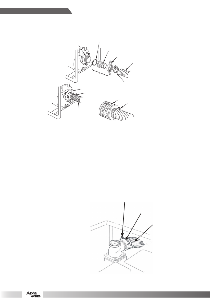
1. Clean water pump and high pressure pump are only designed for pumping clean water.
2. To prevent fire hazards and to provide adequate ventilation, keep the pump at least 1 meter
away from each of the building walls and other equipment during operation. Do not place
flammable objects close to the pump and do not fill the fuel tank with gasoline before long
distance transportation.
3. The muffler becomes very hot during operation and remains hot for a while after stopping the
engine. Be careful not to touch the muffler while it is hot. Let the engine cool before storing
the water pump indoors.
4. Gasoline is highly flammable and explosive. Don’t smoke in the refueling and fuel storage
area.
5. Place the pump on a firm, level surface. If the pump is tilted or overturned, fuel spillage may
result.
6. Refuel in a well-ventilated area with the engine stopped, and in places for refueling or storing
gasoline. If spilling occurs, immediately clean it.
7. After refueling, cover the fuel tank well and screw it down.
8. Exhaust contains poisonous carbon monoxide gas that can build up to dangerous levels in
closed areas. Breathing carbon monoxide can cause unconsciousness or death.
1

9. Don’t screw off the plug while the engine is running to avoid damaging the equipment and
hurting the persons.
10. Children and pets must be kept away from the area of operation due to a possibility of
burns from the hot engine components.
11. The machine is forbidden to be operated in a potentially explosive atmosphere.
Safety Label
2

COMPONENT IDENTIFICATION
2"/3"/4" CLEAN WATER PUMP
3
CHOKE LEVER
FUEL TANK CAP
THROTTLE LEVER
DISCHARGE PORT
OIL DIPSTICK
ENGINE SWITCH
RECOIL STARTER GRIP
FUEL COCK
PRIMING WATER FILTER CAP
FRAME
AIR FILTER
MUFFLER
OIL DRAIN PLUG
PUMP DRAIN PLUG
SUCTION PORT
FUEL TANK

CONTROL SYSTEM
Before operating our company's water pump, carefully read and understand the owner’s
manual and be familiar with each control function. Know how to operate and how to do in a
urgency condition.
Fuel Lever
The fuel lever is used for fuel flowing from the fuel tank to
carburetor. Set the fuel lever to the “OPEN” position.
When not operating the engine, set the fuel lever to the
“CLOSE” position.
Engine Switch
The engine switch is used for opening or closing
ignition circuit :
Set the engine switch to the “OPEN” position to
run the engine, and set it to the “CLOSE”
position to stop the engine.
Choke Lever
The choke lever is used for opening and closing the
choke of the carburetor.
Set the choke lever to the “CLOSE” position for
cold starting.
Set the choke lever to the “OPEN” position for
normal operation or the Engine's warm starting.
4
FUEL LEVER
CLOSE
OPEN
OPEN
CLOSE
CHOKE LEVER
CLOSE
OPEN

5
Throttle Lever
Adjust the throttle lever to change speed of the
engine, thereby adjust the discharge water.
For a bigger water discharge, set the throttle
lever to the
HIGH position, for a smaller water discharge,
set the throttle lever to the LOW position.
Recoil Starter
Pull the recoil starter to start the engine.
NOTICE: Don’t allow the starter grip
to snap back against the engine. Return
it gently to prevent damage to the starter.
PRE-OPERATION INSPECTION
For your safety and to maximize the service life of your equipment, it is very important to take a
few moments before you operate the pump to check its condition. Be sure to take care of any
problem you find before you operate the pump, contact the AlphaWORKS customer service
center by 1-866-493-0524 for any assistance.
Improperly maintaining this pump or failing to correct problems before operation could
cause a malfunction in which you could be seriously injured.
1. Exhaust gas contains poisonous carbon monoxide. Avoid inhalation of exhaust gas. Never
run the engine in a closed garage or an enclosed area.
2. To prevent fire hazards, keep the pump at least 1m away from each of the building walls and
other equipment during operation. Do not place flammable objects close to the engine.
3. Before beginning your pre-operation checks, be sure the pump is on a level surface and the
ignition switch is in the OFF position.
Routine Check
1. Look around and underneath the pump for signs of oil or gasoline leaks.
2. Remove any excessive dirt or debris, especially from around the engine muffler and recoil
starter.
3. Look for signs of damage.
4. Check to confirm that all nuts, bolts, screws, hose connectors and clamps are tightened.
Check The Suction And Discharge Hoses
1. Check the general condition of the hoses. Be sure the hoses are in serviceable condition
before connecting them to the pump. Remember that the suction hose must be of a
reinforced construction to prevent hose collapse.
THROTTLE LEVER
HIGH
LOW

2.
Check to ensure that the sealing washer in the suction hose connector is in a good condition.
3. Check to ensure that the hose connectors and clamps are securely installed.
4. Check to ensure that the strainer is in a good condition and is installed on the suction hose.
Check Engine Oil
NOTICE: Put the engine on a level place and check the engine oil.
1) Remove the oil filler cap and wipe the dipstick clean.
2) Check the oil level by inserting the dipstick into the filler neck without screwing it in.
3) If the level is low, add the recommended oil to the upper mark on the dipstick.
4) After adding, don’t forget to refit and screw down the oil dipstick.
NOTICE: Engine operating with oil at the lower oil mark will cause engine damage.
Check Air Filter
A dirty air filter will restrict air flow to the carburetor, reduce
engine performance and thereby reduce water Pump
performance. So, often check the air filter.
Screw off butterfly nut and remove air filter housing,
If the element is
dirt, clean it, if it is damaged, replace with a new one.
If it is an oil bath air filter, Check the oil capacity.
Reinstall the air filter back in reverse order and screw
the butterfly nut down.
NOTICE: Assembly should be correct, Never run
the water pump without the air filter or with a
damaged air filter assembled, if so, rapid
enginewear will result.
Check The Fuel
Before each operation, check the engine oil level with the water pump stopped on a level
ground. Screw off the fuel tank cap and check the fuel level. If the level is too low, add fuel,
screw on the fuel tank cap and tighten it after refueling.
NOTICE: Don’t add the fuel over the fuel strainer shoulder(maximum level).
6
OILING HOLE
OIL DIPSTICK
OIL LOWER MARK
FUEL TANK TOP
FUEL UPPER LIMIT

Refuel in a well-ventilated area. If the engine has run for a while, it has to be cooled before
being refueled.
NOTICE: Fuel can damage paint and plastic. Be careful not to spill fuel when filling your
fuel tank.
Fuel Recommendations
Use gasoline with octane rating ≥90.
We recommend unleaded gasoline because it produces fewer engine deposit and spark plug
deposit and extends exhaust system's life.
Never use stale or contaminated gasoline or oil/gasoline mixture. Avoid getting dirt or water in
the fuel tank.
OPERATION
Safe Operating Precautions
To safely utilize the full potential of this pump, you need a complete understanding of its
operation and a certain amount of practice with its controls.
Before operating the pump for the first time, please review the "Safety Instruction" (refer to
page 1) and the "PRE-OPERATION INSPECTION".( refer to page 5)
Exhaust contains poisonous carbon monoxide gas that can build up to dangerous levels in
closed areas. Breathing carbon monoxide can cause unconsciousness or death.
Pump Placement
For best pump performance, place the pump near the water level, and use hoses that are no
longer than necessary. That will enable the pump to produce the greatest output with the least
self-priming time.
As head increases, pump output decreases, The length, type and size of the suction and
discharge hoses can also significantly affect pump output.
Minimizing suction head (placing the pump near the water level) is also very important for
reducing self-priming time.
7
DISCHARGE
HEAD
SUCTION
HEAD
TOTAL HEAD

HOSE CLAMP
HOSE CONNECTOR
DISCHARGE HOSE
Suction Hose Installation
Use the commercially available hose and hose connector, and the hose clamp provided with
the pump to install the suction, and tighten the clamp. Firmly fix the suction hose without
moving.
Hose dimension should be longer than water suction port dimension.
Minimum hose dimension shall be 2" (50mm).
Use a hose clamp to securely fasten the hose connector to the suction in order to prevent air
and water leakage. Check to ensure that the hose connector sealing washer is in a good
condition.
Install the strainer (provided with the pump) on the other end of the suction hose and secure it
with a hose clamp. The strainer will help prevent the pump from becoming clogged or damaged
by debris.
Discharge Hose Installation
Use the commercially available hose and hose connector, and the hose clamp provided with
the pump to install the discharge, and tighten the clamp. Firmly fix the discharge hose without
moving.
It is best to use a short, large-diameter hose,
because that will reduce fluid friction and
improve pump's output.
Tighten the hose clamp securely to prevent
the discharge hose from disconnecting
under a high pressure.
8
SUCTION HOSE
SUCTION PORT SEALING WASHER
HOSE CONNECTOR
HOSE CLAMP RING
SUCTION HOSE
HOSE CLAMP
HOSE CONNECTOR
HOSE CLAMP
STRAINER
HOSE CLAMP
COUPLING
ASSEMBLY

Priming The Pump
Before starting the engine, make sure to fill the pump with water: screw off the priming plug
and prime the pump fully with clean water.
Don't screw off the priming plug during operation of the pump to avoid damaging the equipment
and injuring persons. Reinstall the priming plug and tighten it securely after priming.
NOTICE: Dry operating of the pump will destroy the pump seal. If the pump has been
operated in a dry state, stop the engine immediately and allow the pump to cool before
being primed.
STARTING THE ENGINE
1) Screw the priming plug off and prime the pump
with water until the water is overflowing (water
pump set shall be placed on a level ground).
2) Move the fuel valve lever to the “ON” position.
3) To start a cold engine, move the choke lever to
the “OFF”position.
9
PRIMING WATER FILLER CAP
ON
FUEL VALVE LEVER
CHOKE
LEVER
ON
OFF

ON
CHOKE LEVER
4) Move the throttle lever away from the “SLOW”
position about 1/3 of the way toward the
“FAST” position.
5) Turn the engine switch to the “ON” position.
6) Pull the starter grip lightly until
resistance is felt, the pull it briskly.
NOTICE: Do not allow the starter grip
to snap back against the engine. Return
it gently to prevent damage to the starter.
7) If the choke lever was moved to the OFF
position to start the engine, gradually
move it to the ON position as the
engine warms up.
8) Setting engine speed
After starting the engine, move the throttle
lever to the FAST position for self-priming,
and check pump output.
Pump output is controlled by adjusting
engine speed, moving the throttle lever
in the FAST direction will increase pump
output, and moving the throttle lever in
the slow direction will decrease pump
output.
10
SLOW
THROTTLE LEVER
FAST
ENGINE SWITCH(the
“ON” position.)

STOPPING THE ENGINE
To stop the engine in an emergency, simply turn the engine switch to the OFF position.
Under normal conditions, use the following procedure:
1) Move the throttle lever to the SLOW position.
2) Turn off engine switch: Turn the engine
switch to OFF position.
3) Turn fuel valve lever off: Turn the fuel
valve lever to OFF position.
After use, remove the pump drain plug and drain
the pump chamber.
Remove the filler cap and flush the pump chamber
with clean, fresh water. Allow the water to drain
from the pump chamber, then reinstall the filler
cap and drain plug.
MAINTENANCE
The engine must be properly maintained to ensure its operation be safe, economy and
trouble-free, as well as eco-friendly.
In order to keep your gasoline engine in good working condition, it must be periodically
serviced. The following maintenance schedule and routine inspection procedures must be
carefully followed
11
ENGINE SWITCH(the
“OFF” position.)
THROTTLE LEVER
FAST SLOW
OFF
FUEL VALVE LEVER

NOTICE:
● If the gasoline engine frequently work under high temperature or heavy load,change the oil
every 25 hours.
● If the engine frequently work under dusty or other severe circumstances, clean the air filter
element every 10 hours; If necessary, change the air filter element every 25 hours.
● The maintenance period and the exact time (hour), the one which comes first should govern.
● If you have missed the scheduled time to maintain your engine, do it as soon as possible.
Stop the engine before servicing. Put the engine on a level surface and remove the spark plug
cap to prevent the engine from starting.
Never run your engine in a poorly ventilated room or other enclosed area, be sure to keep good
ventilation in working area. The exhaust from the engine may contain poisonous CO, inhalation
can cause shock, unconsciousness and even death.
12
Frequency
Items
Each
time
First 1 month
of operation
Thereafter, every
3 months or every
50hrs of opera-
tion
Every yearor
every 100 hrs
of operation
Engine oil Replace √ √
Reduction gear
oil(if equipped)
Oil level check √
Replace √ √
element
Check √
Clean √
Replace √
Deposit Cup( if
equipped) Clean √
Spark Plug Check - adjust √*
Spark arrester Clean √
Idling ( if
equipped)** Check - adjust √
Valve clearance
** Check-adjust √
Fuel tank & fuel Clean √
Fuel line Check Every 2 years( change if necessary)
Cylinder head,
piston
Clean up carbon
**
<225cc,Every 125hrs
≥225cc,Every 250hrs
*These items should be replaced if replacement needed.
** These items should be maintained and repaired by our authorized dealer, unless the

Engine oil change
Drain the used oil while the engine is warm. Warm oil drains quickly and completely.
1. Place a suitable container below the engine to catch the used oil, then remove the oil filler
cap/dipstick and the drain plug.
2. Allow the used oil to drain completely, then reinstall the drain plug, and tighten it securely.
Please dispose of used motor oil in a manner that is unharmful to with the environment. We
suggest you take used oil in a sealed container to your local recycling center or service
station for reclamation. Do not throw it in the trash, pour it in the ground, or down into a
drain.
3. With the engine on a level place, fill it to the upper limit with the recommended oil.
4. Reinstall the oil dipstick and tighten it.
Used engine oil may cause skin cancer if repeatedly left in contact with the skin for prolonged
periods. Although this is unlikely unless you handle used oil on a daily basis, it is still advisable
to thoroughly wash your hands with soap and water as soon as possible after handling used
oil.
Engine oil recommendations
Engine oil is a major factor affecting engine performance
and service life.
Non-detergent and 2-stroke engine oils will damage the
engine and are not recommended.
Recommended oil
4-stroke gasoline oil
SE, SF grades under API service
Classification or SAE10W-30 that is equivalent SG grade.
Of course, you can select according to local temperature.
The recommended operating range of this pump:
23°Fto104°F.
Air Filter Service
A dirty air filter element will restrict air flow to the carburetor, reducing engine performance, if
you operate the pump in very dusty areas, clean the air filter more frequently than specified in
the maintenance schedule.
NOTICE: Never run the engine without the air filter or use a damaged air filter. If so,
rapid engine wear will result.
13
OIL DIPSTICK
UPPER MARK
OIL DRAIN
BOLT
WASHER

Screw off the butterfly nut down and remove the housing. Screw off the other butterfly nut and
remove the element.
1. Wash the element with home detergents and warm water (or nonflammable or high
flash-point cleansing solvents) and dry it up.
2. Soak it in clean engine oil until it is saturated. Squeeze out excess oil.
3. Clean the lower body of the air filter, housing, and rubber cushion. Prevent dusts from
entering into the ail path of the carburetor.
4 Reinstall air filter and screw on the butterfly nut.
Spark Plug Service
Recommended spark plugs: NGK BP6ES or other equivalents.
NOTICE: Wrong model can result in engine damage.
1. Remove the spark plug cap, and clean any dirt from around the spark plug base.
2. Use the plug wrench to remove the spark plug.
3. Measure the plug gap with a feeler gauge. If the electrode or insulator is damaged, replace
the spark plug.
Correct as necessary by carefully bending the side electrode. The gap should be:
0.028in.-0.031in.
4. Check if the spark plug gasket is in good condition. In order to avoid damage to the thread in
the cylinder head, screw in the spark plug carefully by hand.
5. Once the spark plug has touched the washer, screw it down by a spark plug wrench and
compress the washer.
-- If a new spark plug is used, make 1/2 turn more after compressing the gasket.
-- If reinstalling the used spark plug, just make 1/8-1/4 turn more.
6. Install the spark plug cap.
STORAGE
1) Remove priming plug and drain plug, flush the chamber with clean water, reinstall the
priming plug and drain plug. After stopping the engine, cool for half an hour at least, then
flush all outer surfaces and wipe it.
NOTICE: Higher pressure flushing water can enter into the air filter and muffler, even
entering into the cylinder along the air path, resulting in corrosion and damage. So,
operation must be performed only after stopping and cooling.
2) Remove drain plug of the carburetor and sediment cup, then open the fuel lever. Completely
drain the fuel from the carburetor and fuel tank, then install the sediment cup and drain plug
back and tighten them.
14
0.028in.-0.031in.
SPARK PLUG
SOCKET WRENCH
SPARK PLUG CAP

3) Change the engine oil.
4) Pour a tablespoon (0.17oz-0.34oz) of clean engine oil into the cylinder.
Crank the engine several revolutions to distribute oil in the cylinder.
Reinstall the spark plug back.
5) Pull the starter grip slowly until resistance is felt. During such a process, intake and exhaust
valves keep closed to restrict the moisture entering into cylinder head, then, return the
starter grip gently.
6) Repair damaged enamel paint, and apply a thin film of grease to the areas likely to be rusty.
7) Cover a dust-proof sleeve on the water pump and place it in the ventilated area.
15
FUEL LEVER
WASHER
DRAIN PLUG
SEDIMENT CUP
O-RING

TROUBLESHOOTING
Engine
16
ENGINE WILL
NOT START CAUSE CORRECTION
Check Control Parts
Fuel valve OFF. Move fuel valve lever to ON
position.
Choke open. Move choke lever to CLOSED
position unless engine is warm.
Engine switch OFF. Turn engine switch to ON.
Check Fuel
Out of fuel. Refuel.
Bad fuel, pump stored without
treating or draining gasoline or
refueling with bad gasoline.
Drain fuel tank and carburetor,
refuel with fresh gasoline.
Remove And Inspect
Spark Plug
Spark plug faulty fouled or im-
properly gapped.
Adjust gap or replace with a
new spark Plug
engine).
Dry and reinstall spark plug,
start engine with throttle lever
in FAST position.
Contact the
AlphaWORKS
customer service
center by
1-866-493-0524
for assistance
Fuel filter clogged, carburetor
malfunction, ignition malfunc-
tion, valves stuck, etc.
Replace or repair.
ENGINE LACKS
POWER CAUSE CORRECTON
Check Air Filter El-
ement Element clogged. Clean or replace the element.
Check Fuel Bad fuel. Drain fuel tank and carburetor,
refuel with fresh gasoline.
Contact the
AlphaWORKS
customer service
center by
1-866-493-0524
for assistance
Fuel filter clogged, carburetor
malfunction, ignition malfunc-
tion, valves stuck, etc.
Replace or repair.

Water pump
17
NO PUMP OUTPUT CAUSE CORRECTION
Check pump chamber Pump not primed. Prime pump.
Check suction hose
Hose collapsed, cut or
punctured. Replace hose.
Strainer not completely
underwater.
Sink the strainer and the end of a suc-
tion hose completely underwater.
Air leak at connector.
Replace sealing washer if it is missing
or damaged. Tighten hose connector
and clamp.
Strainer clogged. Clean debris from strainer.
Measure suction and
discharge head Excessive head. Relocate pump and hoses to reduce
head.
Check engine Engine lacks power. See “engine lacks power”
LOW PUMP OUTPUT CAUSE CORRECTION
Check Suction Hose
Hose collapsed, cut or
damaged, too long, or
diameter too small.
Replace hose.
Strainer not completely
underwater.
Sink the strainer and the end of a suc-
tion hose completely underwater.
Air leak at connector.
Replace sealing washer if it is missing
or damaged. Tighten hose connector
and clamp.
Check Discharge Hose
Hose damaged, too
long, or diameter too
small.
Replace discharge hose.
Measure Suction And
Discharge Head Critical head. Relocate pump and hoses to reduce
head.
Check Engine Engine lacks power. See “engine lacks power”

ELECTRIC DIAGRAM
18
This manual suits for next models
1
Table of contents
Other ALPHA WORKS Water Pump manuals
Popular Water Pump manuals by other brands

fluidra
fluidra Rainbow Astralpool eCombi EE2 Installation and operating instructions

Ecotech Marine
Ecotech Marine MP40w ES VorTech Setup guide

Agilent Technologies
Agilent Technologies 1260 Infinity user manual

Elektro Maschinen
Elektro Maschinen WPEm 7000/50R Operating instruction

WIKA
WIKA CPP10-H operating instructions

Messner
Messner eco-X2 4500 manual