Sky PDS4250 User manual

Plasma Display
User Guide
PDS4250
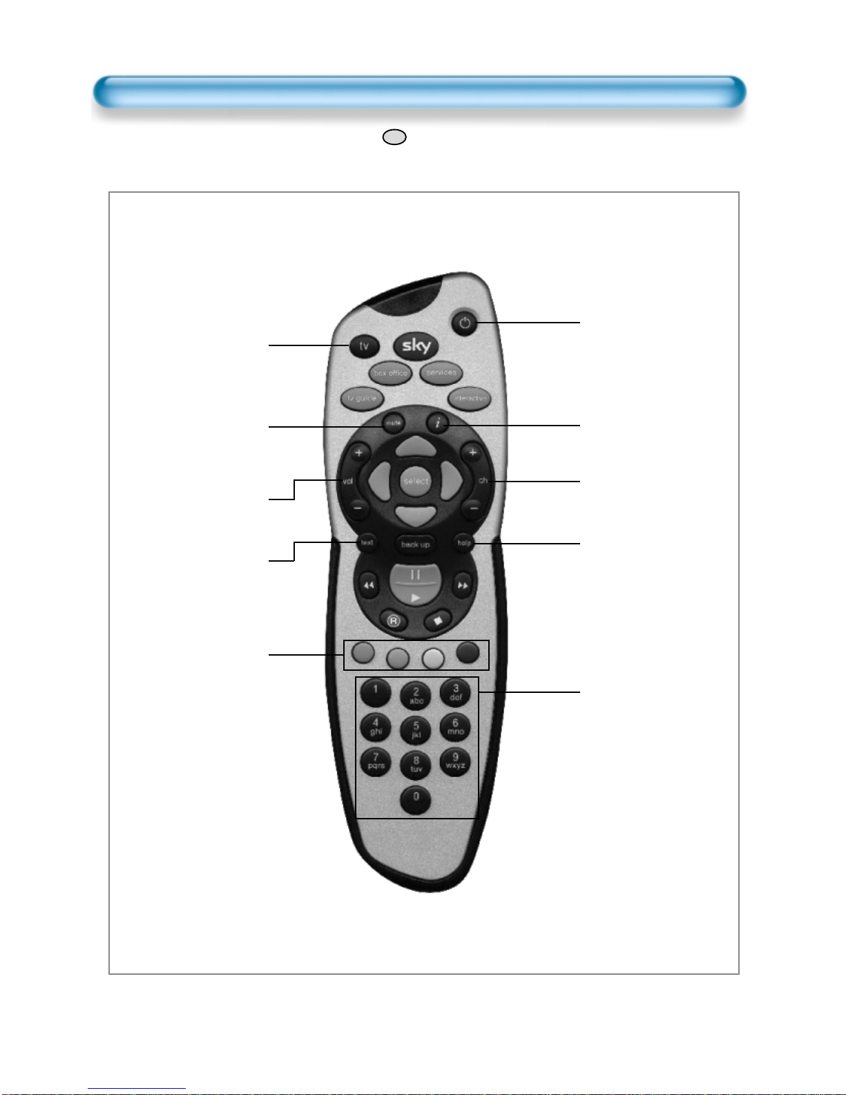
Using your Sky+remote control with Sky Plasma Screen
tv
Sets your remote
control to operate the
plasma screen.
mute
Turns the sound from
the plasma screen off
and on.
vol + and -
Changes the plasma
screen volume.
text
Freezes the screen.
Colour keys select
mode options for the
plasma screen.
Red : Sound mode
options.
Green : Picture mode
options.
Yellow : Screen mode
options.
Blue : Screen menu.
Standby
Turns your Sky+box
and your plasma
screen on and off.
i
Displays the input
selection.
ch + and -
Changes the zoom of
the screen.
help
Selects input options
available on the
plasma screen.
Number keys control
input selections and
highlight menu options.
1: component 1 / 2
input toggle
2: menu up
3: AV 1 / 2 / 3 input
toggle
4: menu left
6: menu right
7: DVI input
8: menu down
9: PC input
To operate the plasma screen press to start screen options
3
tv

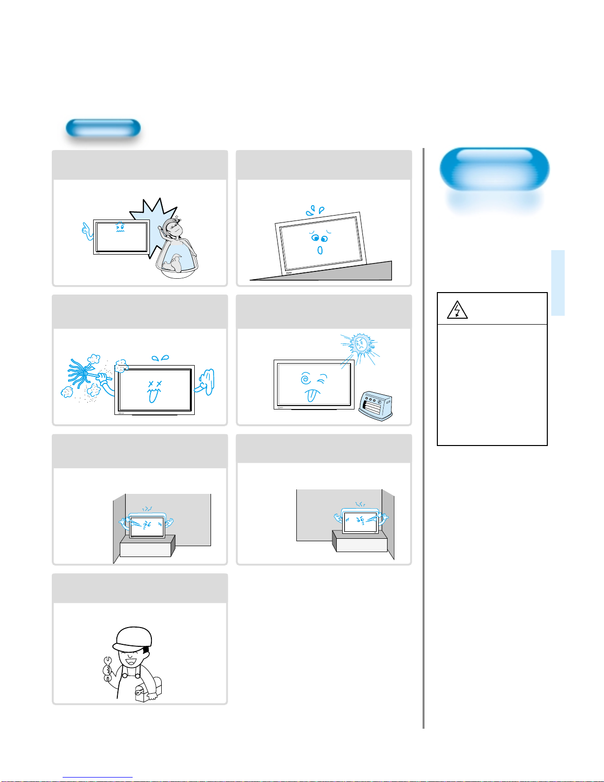
Always obey all
safety messages.
•All the safety and
operating
instructions should
be read before the
product is operated.
If anything strange
happens, unplug
this product from
the wall outlet.
•Do not disassemble
or replace any parts
of the monitor.
Refer to a qualified
service personnel
for repair.
For Your Safety
4
WARNING
You can be killed
or seriously
injured if you do
not follow
instructions.
During a lightning storm, or when left
unattended and unused for long periods
of time, unplug from the wall outlet.
When unplugging your monitor, always
grip plug firmly and pull straight out from
the power socket.
A damaged power cord could cause a fire or an
electric shock.
This product must be properly grounded.
• Improper grounding may cause a malfunction or
an electric shock.
• When proper grounding is not possible, install
circuit breaker.
• Do not ground to gas pipe, water pipe, lightning
rod or telephone line.
During a lightning storm, unplug the
monitor from the wall outlet, and do not
touch the antenna.
Failure to do so could cause a fire or an electric
shock.
Power
When moving your monitor, remove the
power plug, antenna, and cables, and be
sure to move it by at least two people..
Failure to follow this instruction can result in
electric shock or personal injury.
Do not touch the power plug with wet
hands when plugging or unplugging.
It can result in a risk of electric shock.
5
Installation
Do not install the product where it will be exposed to
the direct sunlight, and the product should not be
near heat sources such as radiators, stoves, etc.
It may cause malfunction.
Do not install where there is oil, smog,
moist, and dust.
It may cause malfunction.
For proper ventilation, separate the product
from the wall, and keep a distance of more
than 4”.
Due to the increase of temperature inside the
Monitor, it may cause fire.
Do not place the monitor where
ventilation is not ensured.
Due to the increase of temperature inside the
Monitor, it may cause fire.
If you wish to install this product on the
wall or ceiling, refer to the professional.
Failure to do so may cause damage to product
and injury to human.
Do not use this product in the bathroom
or near a shower.
It can result in electric shock or fire.
Do not place this monitor on an unstable
platform (stand, trolley or table)
It may cause the product and platform to overturn,
damaging equipment or causing possible injury.
Always obey all
safety messages.
• All the safety and
operating instructions
should be read before
the product is
operated.
CAUTION
To avoid injury or
damage to this
product (or any
other property)
please read and
follow these
instructions
carefully.
6
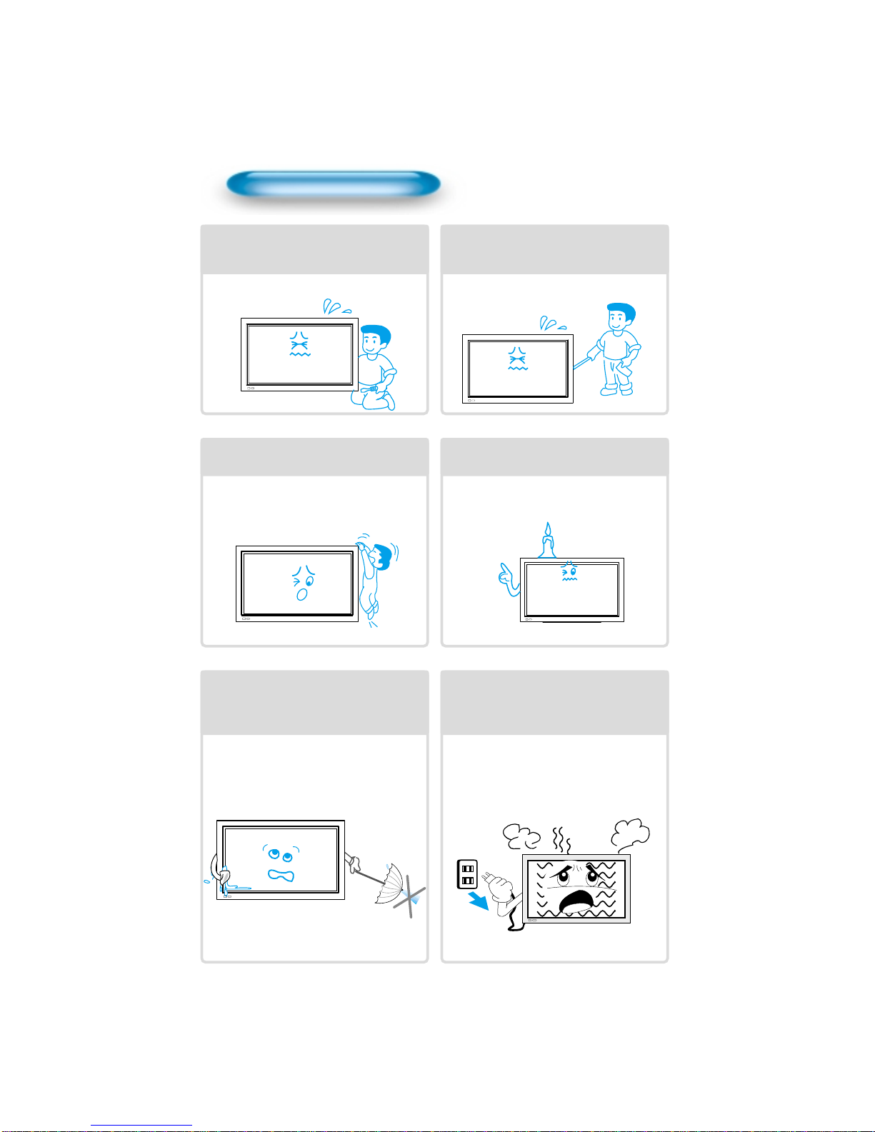
Using The Monitor
Do not open cover (or back).
High voltage’s are present within the
monitor’s enclosure.
It may cause electric shock.
Never push objects of any kind into
this product through openings at the
back of monitor.
It may cause fire or electric shock.
Do not allow children to play or hang
on the monitor.
These actions may tip it over, causing
personal injury.
Do not place candle or lighted
cigarette on the monitor.
If these fall into the inside of the monitor, it
may cause fire or explosion.
Do not spray water on to the monitor
or wipe with damp cloth.
It may cause electric shock or fire.
Unplug the monitor from the power
socket if smoke or strange smell
occurs. Immediatly refer to a service
technician.
In the case of continuous use, it may cause
fire or electric shock.
77
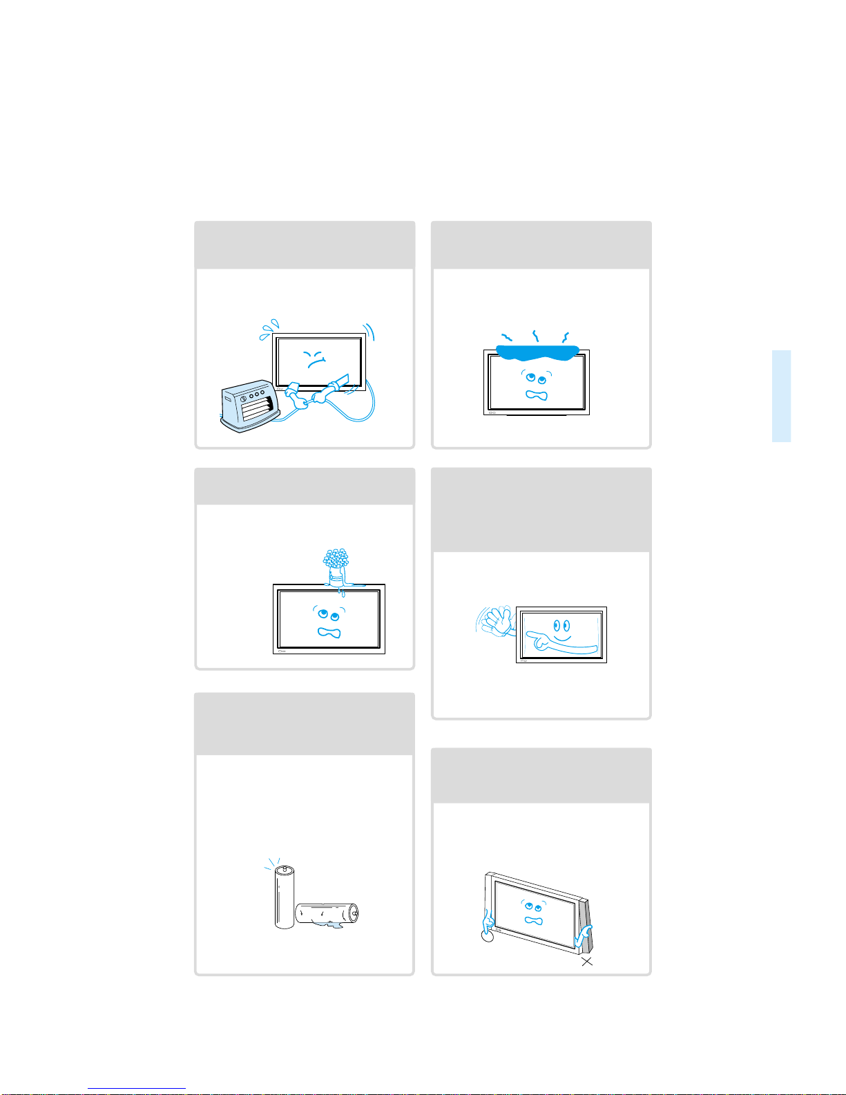
Do not place any object or cover on
the panel.
In an event of improper ventilation, the
panel will be overheat causing fire.
Do not place heavy objects or heat
sources on the power cord.
It may damage the power cord, causing fire
or electric shock.
Do not grip speakers when moving
the panel (if speakers are attached).
When moving the panel, remove the
speakers. Speakers may fall off the panel
due to their weight, causing possible
damage personal injury.
Do not allow a still picture to be
displayed for an extended period, as
this can cause a permanent ghost
image to remain on the plasma
panel. Please refer to the ISM in this
guide.
Examples of still pictures include logos,
video games, computer images, teletext
and images displayed in 4:3 mode.
Warranty does not cover any damage
caused by image retention.
Never place objects filled with liquids
on the monitor.
Spilled liquids may cause electric shock or
fire.
Do not disassemble batteries, and
do not allow children to swallow
them.
Heavy metal may contaminate environment,
and can be harmful or detrimental to human
health. (If your child swallow a battery, go to
hospital and consult with a doctor.)

8
Audio Cable
1UNIT
PC(15pin D-sub) Cable
1UNIT
A/V Cable
2UNITS
AC Cable 1 UNIT
Note
Check to be sure that the following items are
packed with your plasma panel.
INPUT
SELECTPOWER
DISPLAY
ZOOM
-
PICTURE
MODESCREEN
MODE
FREEZE
MUTE
SOUND
MODESLEEP
ZOOM+
MENU
VOLVOL
Remote Control
1UNIT
Checking Accessories
Supplied Accessories
Batteries(AAA) 2 UNITS
9
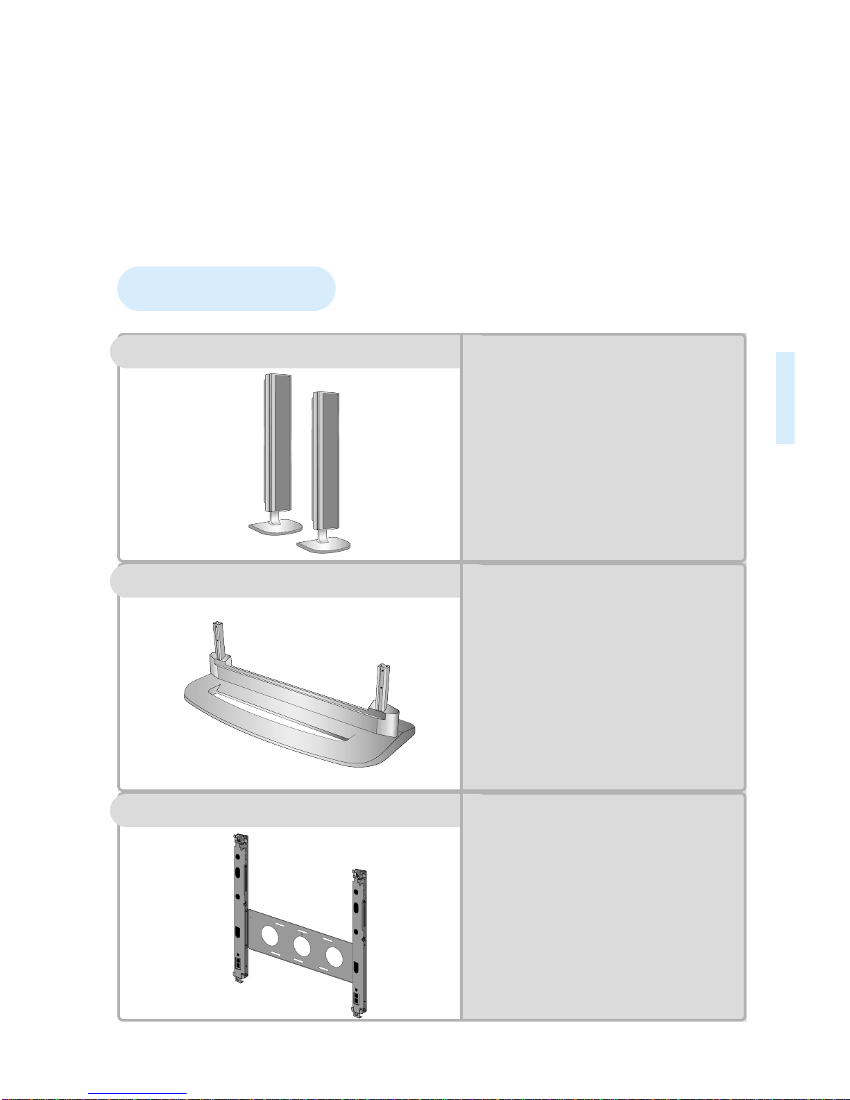
Optional Accessories
SP425
-
Speaker Main Unit
Dimension : 100(W) x 628(H) x 88.5(D)mm
-
Including Speaker Stand
Dimension : 210(W) x 704(H) x 210(D)mm
-
Audio Amplifier : 8W + 8W
-
Impedance : 8Ω
-
Weight : 7kg
ST425
-
Dimension : 720(W) x 215(H) x 310(D)mm
-
Weight : 4.5kg
HG425(optional extra)
•
Variable Angles : 0º, 10º, 15º, 20º
Speaker Main Unit
•
Dimension : 601(W) x 592(H) x 35(D)mm
Including Stand
•
Weight : 4.5kg
Wall Mounting Unit
Table Top Stand
Speakers

11
12 •Panel Controls
13 •Remote control
PREPARATION
BASICS
14 •Installation Instructions
15 •Connecting Speaker to PDP
CONNECTION
18 •Watching a DVD Image
20 •Watching a VCR Image
22 •Watching a Camcorder/Game Console Image
24 •Connecting PC(15pin D-sub)
26 •Connecting PC(DVI)
28 •PC and DVI Input Resolution Available in PDP
APPLICATION
29 •Selecting Auto Picture Mode
30 •
Customizing Picture
32 •
Adjusting Screen Size
34 •Adjusting Screen Position and Size
36 •Enlarging Screen Size
38 •Watching a Still Image
39 •Adjusting Auto Sound Mode
40 •Customizing Sound Mode
42 •Selecting INPUT SIGNAL
44 •Checking the Current Input Signal
45 •
Selecting MENU Background Screen and Languages
48 •Selecting Image Sticking Minimization
49 •Setting Sleep Timer
MISC.
50 •Before Requesting Service
51 •SPECIFICATIONS
CONTENTS

Panel Controls
12
Front Panel, Back Panel, Remote Control
*
Items having same names on the plasma panel and the remote control will function in exactly the
same way.
Front
Rear
RS-232C PORT
AC IN
SPEAKER(8Ohms)
RL
PC INPUT
L
R
AUDIO
DTV/DVDINPUT
L-AUDIO -R
AV3
L
R
AUDIO
S-VIDEO VIDEO
DVI-INPUT
L
R
AUDIO
AV2 AV1
RS-232C PORT
AC IN
SPEAKER(8 Ohms)
RL
PC INPUT
L
R
AUDIO
DTV/DVD INPUT
L- AUDIO -R
AV3
L
R
AUDIO
S-VIDEO VIDEO
DVI-INPUT
L
R
AUDIO
AV2 AV1
ON/OFF
•Power control sensor
•Power Standby: Red - Standby
Green - ON
Power button
DVI-INPUT External Speaker
PC INPUT COMPONENT A/V jacks
(DTV/DVD INPUT jacks) S-VIDEO, A/V INPUT,
Cable Receiver INPUT
jacks
Power
Select when adjusting volume or
select/adjust “MENU.”
Press when moving “MENU.”
STAND BY/OPERATE
SCART, A/V
INPUT/OUTPUT,
Cable Receiver
INPUT/OUTPUT jacks
Used when
manufacturing (For
manufacturer use only)
Other manuals for PDS4250
1
Table of contents
Other Sky Monitor manuals


