Skydio SkydioLink User manual

SkydioLink 5GHz Radio User Manual
version 1.0 (2021/03/16)

Overview
This document provides integration, installation and usage instructions for the
SkydioLink 5GHz Radio (FCC 2ATQRSMO5GV1 / IC 25280-SMO5GV1).
Module Integration
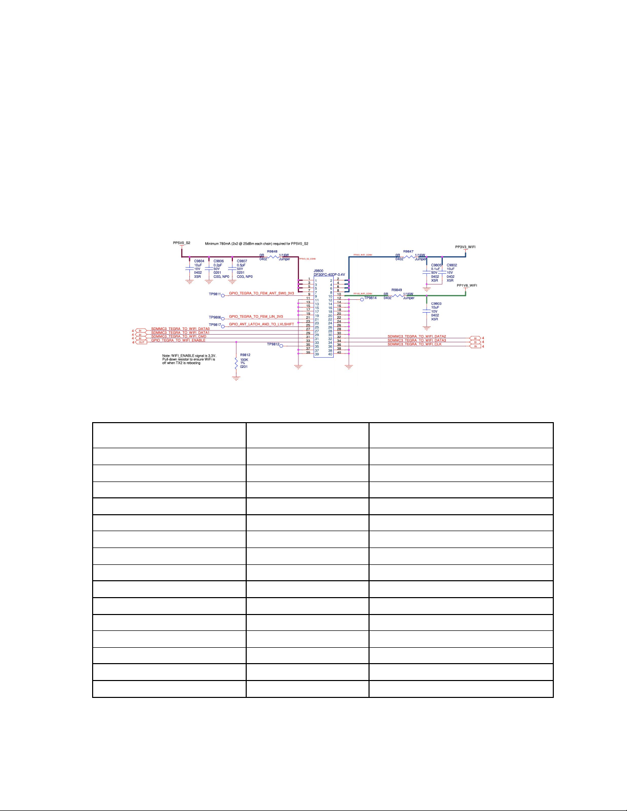
Pinout & power requirements
All module power and control signals are passed from the end device to the
module over J9800, following the below pinout:
Detail on pin-out requirements:
Pin Number
Required Signal
Purpose
1, 3, 5, 7
5V (780 mA minimum)
5V Supply for RF front end modules
2, 4, 6, 8
3.3V
3.3V Supply for Switcher & QCA617A
9
Unused GPIO
10
1.8V Supply for QCA6174A
21
Unused GPIO
25
Unused GPIO
27
SDIO Data (0) from Host to WiFi
29
SDIO Data (1)) from Host to WiFi
31
SDIO Command from Host to WiFi
32
SDIO Data (2) from Host to WiFi
33
WiFi enable signal from Host
34
SDIO Data (3) from Host to WiFi
35
-
test point
36
SDIO Clock from Host to WiFi
11 - 20, 23, 23, 26, 28, 30, 37 - 40
-
Ground
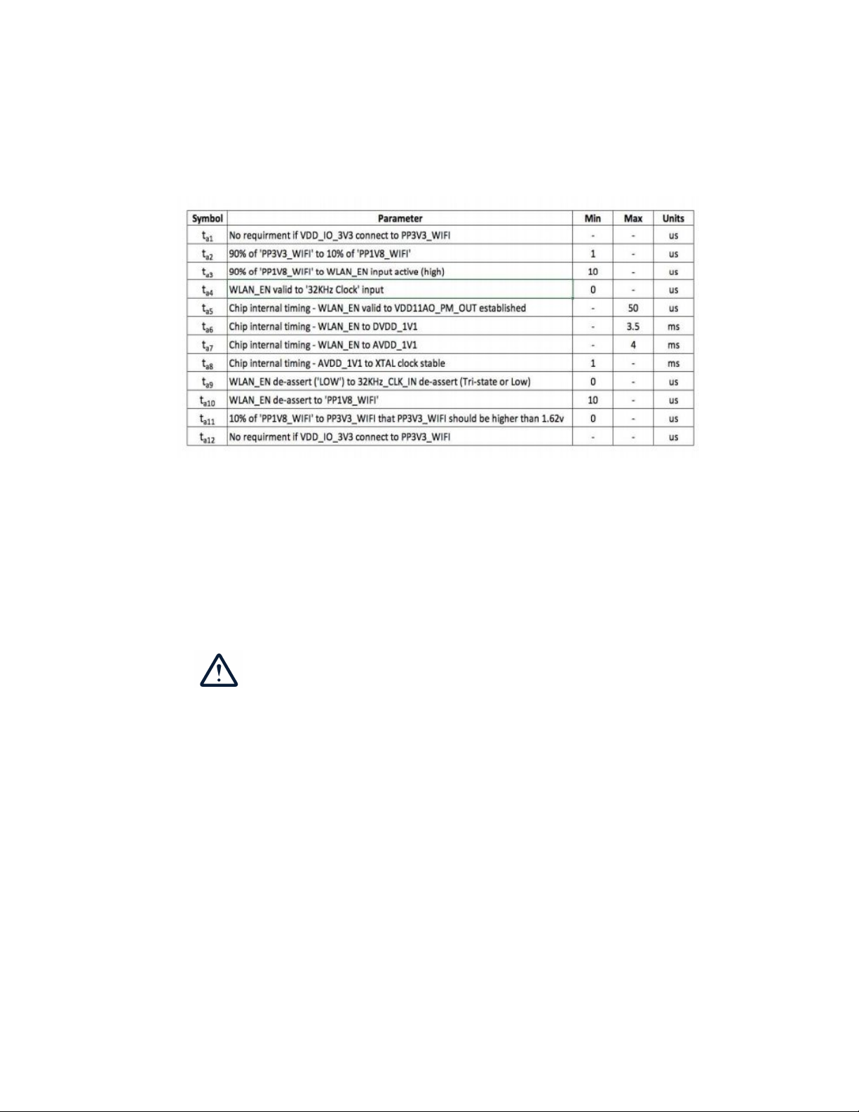
Boot Sequence
When first turning on the radio, the below power on sequence must be used to
ensure that the radio will operate correctly:
Module Mechanical Integration
The SkydioLink 5GHz Radio snaps into place using the two board to board
connectors (Hirose DF30FC-40DP-0.4V) on the lower side of the module. All
power and signal lines are passed via J9800, and J9801 is only used to secure
the module in place instead of using screws.
When installing the module, it is important to
ensure that the technician using ESD
protection
On the end device, the spacing and board to board MPN must match the
module side specifications:
Mating board to board type: DF30FC-40DS-0.4V
Mating Board to board spacing: 38.44mm,

Antenna Connectors
The radio module uses two I-PEX u.FL connectors (20441-001E-01) to connect
external antennas to the module. The connectors are snapped an place, and
do not require any external pressure or screws.
On the antenna cable, the mating connector is an I-PEX 20351-1 series (or
equivalent) connector. Antenna types and gains must follow the FCC / IC
regulatory filings submitted by Skydio.
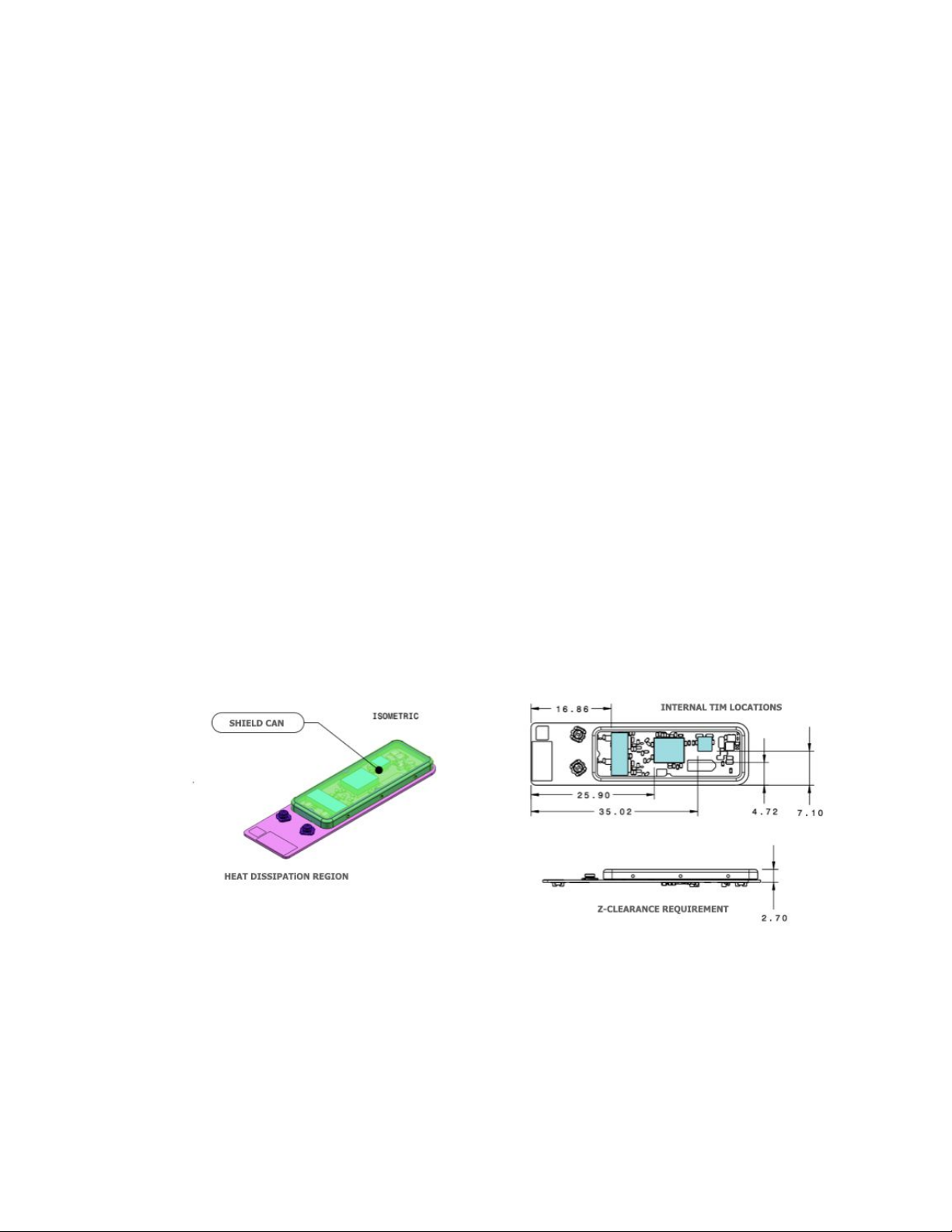
Thermal Management
In order to prevent overheating when operating at high power levels, it is
important to move heat out of the module. It is recommended to heat sink via
the shield can on the top of the module, which has a direct thermal interface
to the radio & front end module components that generate the most heat.
An example of this is shown below on the Skydio X2 UAV, using a graphite
strap to move heat from the module to the UAV chassis.
Usage Guidelines
Power & frequency settings are not advised to be exposed to the user, and should
be set at the factory to ensure that the radio is correctly configured relative to the
regulatory filings submitted by Skydio.
Regional Settings
All power levels & frequency bands must follow regional restrictions. Two
methods can be used to ensure that these are followed:
1. During a factory installation, set the power tables based on the
intended country of sale for the specific end device SKU
2. Use GPS data from the host device to select a specific power table to be
referenced. This is recommended for devices that are portable.
Note that the end device ultimately controls power levels, frequency band and
other radio settings and it is up to the end device manufacturer to ensure
compliance with existing filings for this module.
Mechanical Requirements

Compliance Information
FCC
Any changes or modifications to this equipment not expressly approved by
Skydio for compliance will void the user’s authorization to operate this
equipment.
This equipment has been tested and found to comply with the limits for a Class A
digital device, pursuant to part 15 of the FCC Rules. These limits are designed to
provide reasonable protection against harmful interference when the equipment
is operated in a commercial environment. This equipment generates, uses, and
can radiate radio frequency energy and, if not installed and used in accordance
with the instruction manual, may cause harmful interference to radio
communications. Operation of this equipment in a residential area is likely to
cause harmful interference in which case the user will be required to correct the
interference at his own expense.
This device complies with part 15 of the FCC Rules. Operation is subject to the
following two conditions: (1) This device may not cause harmful interference, and
(2) this device must accept any interference received, including interference that
may cause undesired operation.
This equipment complies with FCC radiation exposure limits set forth for an
uncontrolled environment. The distance between user and products should be
no less than 20cm. The end user must follow the specific operating instruction for
satisfying RF exposure compliance. This transmitter must not be co-located or
operating in conjunction with any other antenna or transmitter.
IC
The installer of this radio equipment must ensure that the antenna is located or
pointed such that it does not emit RF field in excess of Health Canada limits for
the general population; consult Safety Code 6, obtainable from Heath Canada’s
website www.hc-sc.gc.ca/rpb
L'installateur de cet équipement radio doit s'assurer que l'antenne est située ou
pointée de manière à ne pas émettre de champ RF au-delà des limites données
par Santé Canada pour la population générale; consultez le Code de sécurité 6,
disponible sur le site Web de Santé Canada www.hc-sc.gc.ca/rpb.
Table of contents


