Skye APOLLO SKA 400 User manual
Apollo Display Meter
SKA 400
Skye Instruments Ltd.,
21 Ddole Enterprise Park,
Llandrindod ells,
Powys LD1 6DF UK
Tel: +44 (0) 1597 824811
www.skyeinstruments.com Iss. 1.1

Skye Instruments Ltd.
Skye Instruments is based in the UK and we are very proud to be celebrating being in business since
1983. ur products are designed and built in the UK. We have a very wide product base and our
sensors & systems are used for plant & crop research; micro-climate, global climate change studies;
environmental monitoring and controlled environment installations.
Products include light sensors & systems, weather monitoring sensors, automatic weather stations,
plant research systems, soil and water research systems.
Feel free to contact us via our e-mail, or any of the methods below:
Click on the icons to browse to the sites, or search for the usernames below.
Have a Smartphone? Scan this QR code to access our website for more information about your
product:
Please be aware that the information in this manual was correct at time of issue, and should be 100% relevant to
the accompanying product. We take great pride in our ever-evolving range of products, which means that sometimes
the product may change slightly due to re-design.
If you have any queries, please do not hesitate to contact our technical team by any of the methods above.
Skye.InstrumentsSkye Instruments Ltd. @SkyeInstruments SkyeInstrumentsVideo
Skye Instruments Ltd.

Page
1. INTRODUCTION 1
2. PRINCIPLES OF OPERATION 2
2.1 Taking a reading............................ 2
2.2 Sensor Calibration Data.................. 3
2.3 Viewing Stored Sensor Info............. 3
2.4 Editing Stored Sensor Info.............. 4
3. DISPLAY & KEYPAD 5
3.1 Display.......................................... 5
3.2 Keypad......................................... 5
4. MENU OPTIONS 6
4.1 Menu Overview.............................. 6
4.2 Switch on “Read Sensor”................ 6
4.3 Sensor to Use................................ 7
4.4 Level Offset.................................. 7
4.5 Check Battery................................ 8
4.6 AutoOff Period............................. 8
4.7 Rd Sensor Setup............................ 8
4.8 r Sensr Setup.............................. 9
4.9 Serial Number............................... 9
4.10 Firmware Versn............................. 9
4.11 Msg Duration................................ 10
4.12 Beeper Sounds............................. 10
4.13 Contact Skye................................ 10
4.14 The Skye Team............................ 10
5. PO ER 11
6. SENSOR CONNECTION 11
7. TROUBLESHOOTING 12
8. SPECIFICATIONS 15
APPENDIX 1 – ACCESSORIES
APPENDIX 2 – APOLLO-COMPATIBLE SENSORS
APPENDIX 3 – MENU NAVIGATION TREE
CONTENTS
1. INTRODUCTION
Thank you for purchasing Apollo (SKA400), Skye Instrument’s single-channel display meter. Apollo is
optimised for use with Skye amplified light sensors, but can be used with other manufacturers’ sensors also.
Please see Appendix 2 for more information on what sensors can be used with Apollo.
It is designed to be held and used comfortably in one hand, whilst the other is in control of the sensor.
The menu is easy to navigate, and if bought as part of a package (Apollo + Skye sensor(s)), you can start
taking readings instantly.
Apollo is compatible with single channel, voltage output sensors, with outputs in milliVolts and Volts,
which in turn can be scaled to Wm-2 / mWm-2 / UV-Index*, using data supplied on the calibration certificate
of your sensors. Up to two (scaling factors) can be used for each sensor.
The display whilst taking a reading shows two lines of data, showing either live readings plus units, or
a “held” display using the Hold key. The display can be toggled between two pre-set scaling factors/units.
Apollo is splashproof only (Skye sensors are fully-waterproof as standard), with Binder 5-pin female
socket for sensors.
*UV-Index reading only meaningful with UV-I sensor
1
Apollo Display Meter

2. PRINCIPLE OF OPERATION
2.1 Taking a Reading
If you have bought Apollo as a package with Skye sensors, then it is ready to take a reading
immediately. If you have not ordered an Apollo package, and have another, suitable, sensor to use, please
see Section 2.2 to configure Apollo to work with it.
Install the battery provided, ensuring it is correctly fitted, and attach the sensor via the 5-pin socket
located at the top of Apollo, by matching the sensor and plug using the locating pin, then screwing it finger
tight. There is only one way the socket and plug will match, please be careful.
Switch Apollo on and you will be greeted by a welcome message, then a message that informs you
which sensor configuration is used. After this you are shown the live reading from the sensor on the top line,
along with the units on the bottom line.
Apollo can show the reading in two different units, which can be toggled between in the live reading
screen using the tu buttons. Default units are usually mW m-2 and W m-2,. See Section 2.2 for information on
how to change these units.
For an accurate reading, ensure the sensor is as stationary as possible, and if measuring solar
radiation levels, the sensor is fully upright (Skye also offer a "levelling unit" that will be very useful in field
readings - please see Accessories in Appendix 1). We recommend you take a note of your geographical
location and time of day (so that you may obtain the solar zenith angle at the time), and also cloud cover
(0 to 10 as per WM instructions, where 0 = no cloud cover, and 10 = 100% cloud cover).
If you have more than one sensor in your package, then you may have seen the wrong sensor name
come up. This will result in an incorrect reading being shown. To change the sensor configuration used to the
correct one, go to Menu > Sensor to Use > "Choose appropriate sensor 1-6". The name of the sensor whose
configuration you have selected will show up when you return to Menu > Read Sensor to the live reading.
2
Apollo Display Meter

2.2 Sensor Calibration Data
Apollo will store calibration factors and information for up to 6 different sensors in its memory. These
can be viewed and edited by the user. Each sensor configuration allows two scaling factors to be used (e.g.
mW m-2 / W m-2 / mmol m-2 etc.). Each "sensor storage" will store the information described below, and are
automatically known as sensor 1, 2, 3...6. Editing these configurations can be done by following the steps in
Section 2.4.
Please note that if you bought Apollo in conjunction with a Skye sensor (Apollo Package), Apollo will
already be configured to work with those sensors.
2.3 Viewing Stored Sensor Information
To view the stored sensor configurations, go to Menu > Rd Sensr Setup > "Choose which sensor's configuration to
view" (1-6). Press 6 or [Next] to move to the next item on the list, and 5 to move back to previous item.
Sensor (1-6):
Description
The name given to the sensor. By default this is the type of sensor supplied with Apollo (e.g. UV-A/UV-B etc.). This can be
edited to any phrase the user prefers (limit of 12 characters). This will show when you enter Read Sensor, in order to identify
which sensor configuration is used.
Units (Scale1)
The name of the units of scale 1. By default this is set as mW m-2. Again this can be edited to any phrase the user prefers
(limit of 12 characters). This is shown on the "Read Sensor" screen to identify the units that the reading is scaled to.
/P Units/mV Sc.1
This number relates to how Apollo scales the voltage output of the sensor to a meaningful reading with appropriate units.
This is essentially the amount of the chosen unit that a 1mV reading equals. The Sc.1 in the title refers to which scale is being
viewed.
ffset mV Sc.1
The value of the sensor's "dark" current, or constant offset from zero in mV. Amplified sensors inevitably have a small output
voltage not derived from accepting light, and as such this value needs to be deducted from the reading.
Units (Scale2)
Same as previous, but for scale 2.
/P Units/mV Sc.2
Same as previous, but for scale 2.
ffset mV Sc.2
Same as previous, but for scale 2. You may wish to add your own permanent offset here also, useful for those interested in
observing the change in light from a known/set standard. If doing so, we would suggest stating so in the "Units" value.
Connection Mode
The mode Apollo "connects" to a sensor. Default is Mode 3, which is appliccable to Skye amplified sensors. Please see
Section 6 & Appendix 2 for more details.
3
Apollo Display Meter

2.4 Editing Stored Sensor Information
**Please note that this procedure affects the way Apollo takes readings. You will only need to edit
these values if you buy a new Skye sensor, or would like to use a non-Skye sensor with Apollo. **
All required information is shown on individual sensors' calibration certificate.
Editing information into Apollo is simple. The tu keys changes the character value, and [Next]
button moves onto the next character in the word/number. Holding down (~3 seconds) 5 changes the
character to a capital 'A', and holding down 6 changes the value to a "space". Characters available are
lowercase a-z, uppercase A-Z, numerals 0-9 and symbols ( __ , ---- , / , m ) - i.e. space, dash, slash, micro-.
[Enter] accepts new value, [Esc] ignores new value and reverts to the original. Messages confirm these.
To enter sensor configuration "edit mode", go to Menu > Wr Sensr Setup > Enter Passcode. This menu
is protected by a three digit password. This corresponds to the LAST THREE DIGITS of your Apollo's serial
number. For example, an Apollo whose serial number is SKA-400 12345, the password would be 345. the
serial number can be found by going to Menu > Serial Number.
Description
This can be edited to any phrase the user prefers (limit of 12 characters including spaces). We recommend using the number
of the sensor, plus a brief description of the sensor (e.g. "1 UV-A" /"2 SkyeUV-B"/"3KippZonUV-A" etc.). This identifies sensor
configuration in "Read Sensor" screen.
Units (Scale1)
The name of the units of scale 1. By default this is set as millivolts. Again this can be edited to any relevant phrase the user
prefers (limit of 12 characters including spaces).
/P Units/mV Sc.1
This number relates to how Apollo scales the voltage output of the sensor to a meaningful reading with appropriate units of
scale 1. This is essentially the amount of the chosen unit that equals 1mV. The Scale1 in the title refers to which scale is being
viewed. Default setting is 1.00, so that 1.00mV shows as 1.00 millivolt. (i.e. multiplied by 1.00).
ffset mV Sc.1
The value of the sensor's "dark" current, or constant offset from zero in mV. Some sensors inevitably have a small output
voltage not derived from accepting light, and as such this value needs to be deducted from the reading. Default is 0.00.
Units (Scale2)
The name of the units of scale 2. By default this is set as Volts. Again this can be edited to any phrase the user prefers (limit
of 12 characters including spaces).
/P Units/mV Sc.2
This number relates to how Apollo scales the voltage output of the sensor to a meaningful reading with appropriate units.
This is essentially the amount of the chosen unit that equals 1mV. The numeral 2 in the title refers to which scale is being
viewed. Default setting is 0.001, so that 1.00mV shows as 0.001 Volt. (i.e. multiplied by 0.001).
ffset mV Sc.2
Same as previous, but for scale 2. You may wish to add your own permanent offset here also, useful for those interested in
observing the change in light from a known/set standard. If doing so, we would suggest stating so in the "Units"
value/information. Default is 0.00.
Connection Mode
The mode Apollo "connects" to a sensor. Default is Mode 3, Please see Appendix 2 to identify what connection mode is
required for your sensor to work.
4
Apollo Display Meter

3. DISPLAY & KEYPAD
3.1 Display
Apollo has a 2-line 14 character alphanumeric liquid crystal display (LCD). The meter auto-ranges, and is
designed to show a reading from very low light conditions (even moonlight), and therefore shows a reading
with appropriate significant figures. The live reading can be frozen at any time by using the [Hold] button,
and exited by using [Hold] or [Esc].
During extremely low light conditions, the reading may change constantly due to the high sensitivity of
the meter. To best solve this, ensure the sensor is on a level, solid surface, and wait for the reading to
stabilize. In these instances, it is also advisable to use the [Hold] button to freeze the display, and note the
reading, perhaps doing in triplicate, and averaging the results.
3.2 Keypad
5
Apollo Display Meter
n - This button turns on Apollo and serves no other function.
Esc/ ff - This button when pressed once will cancel the current operation without
making any changes, and exit out of the current menu. A long (3-sec.) press will
turn Apollo off. It will also access the menu from the "live reading" screen.
Enter/Hold - This button will "enter" into the selected menu item, and will confirm
the edit or change of an option (e.g. sensor config., Auto ff period etc.). In the
"live reading" screen, this button will "freeze the display".
Up - Moves "up" in a menu list, choosing the next menu option up. In character
edit screens, will change the value of the character and holding 5 for 3 sec. will
change character value to 'A'.
Down - Moves "down" in a menu list, choosing the next menu option down. In
character edit screens, will change the value of the character and holding 6 will
change character to a "space".
Next - This button will move to the "next" item in the menu (e.g. next option
down), and behaves a lot like the "down" button. Also when editing/entering
information, moves the cursor one space to the right.

4. MENU OPTONS
This section gives an outline of the menu options in Apollo, and goes into detail about what each
option allows you to do. A full menu structure can be seen in Appendix 3..
4.1 Menu Overview
Menu Options:
Main Menu [Esc]
Read Sensor
Sensor to Use
Level ffset
Check Battery
Auto ff Period
Rd Sensr Setup
Wr Sensr Setup
Serial Number
Firmware Versn
Msg Duration
Beeper Sounds
Contact Skye
The Skye Team
4.2 Switch On, elcome Screen & “Read Sensor”
When Apollo is switched on, you are greeted by a welcome screen, which includes the Skye logo, and
Apollo's name. This introduction can be skipped by pressing any key, which will take you to the next screen.
nce the welcome screen is finished, the name of the sensor whose configuration will be used in the reading
is shown briefly (2 seconds), as well as the units of the reading shown on the next screen.
The next screen will be the actual sensor reading on the top line of the display (also accessible by
entering menu [Esc], and selecting "Read Sensor" [Enter]), and the units of that reading appears below.
Apollo can toggle between two units, as configured in the sensor's configuration (scale 1 and scale 2). The
reading will always show scale 1 first, whilst scale 2 can be toggled by pressing the u button, and vice versa
to get back to scale 1. Default units/scales are W m-2 and mW m-2. The display can be "frozen" by using the
[Hold] button, so that a note of the reading can be made easily. this can be exited by using [Hold] again,
or the [Esc] button.
6
Apollo Display Meter
Enters Menu from “live reading” screen (“Read Sensor”)
Scrolls up/down menu items
Selects the menu option and confirms edit/change

4.3 Sensor to Use
This menu option allows you to change which sensor configuration Apollo uses to show the reading.
Choose the sensor number by using the tu buttons, and [Enter] to confirm. A message will confirm
which sensor is now selected. If you do not wish to make any changes, press [Esc], and a message will
appear to confirm no changes were made. Using the incorrect configuration will result in an inaccurate
reading, and this option needs to be changed according to which sensor you are taking readings from.
You may choose from up to 6 different configurations (i.e. 6 different sensors). We recommend you
label your sensors according to which configuraton they correspond to on Apollo. In order to view the sensor
configuration, follow the steps shown in Chapter 2.2.
4.4 Level Offset
This menu option allows you to temporarily "offset" the reading shown in the "Read Sensor" option by
a given value. This is useful if, for example you have a standard source of light, and you wish to compare the
output of other light sources by this standard. The readings on Apollo will then be offset by this amount. This
option is also useful if you find the sensor has a reading of more than 0.00 in complete darkness, and wish
to offset the readings by this amount.
To offset a reading from a standard source of light, [Enter] this menu option, and then place the
sensor directly facing the light source. The reading will now show in milliVolts rather than the units shown in
"Read Sensor" option – this is the "raw" reading from the sensor, and the reading with least error potential.
nce you have a stable reading, press [Enter] to accept the offset value. You will need to keep the sensor
facing the light source and still whilst Apollo obtains the offset value. A message will confirm this change, and
likewise if [Esc] is pressed, a message will confirm that no change has been made..
To offset a reading that is shown when the sensor is in complete darkness, follow the same steps, but
ensure the sensor is covered completely, and can receive no radiation at all during the "offsetting" stage.
ver time, the "dark" reading of many sensors drift. This procedure is a temporary "fix", but we thoroughly
recommend sending the sensor to be re-calibrated by the manufacturer every year: two years maximum.
If you press [Esc] during this stage, you will exit the menu, and a message will confirm that no changes
have been made, and you will be returned to the main menu.
If you have set an offset value, this will be indicated on the "Read Sensor" option by an asterix (*) on
the lower line of the screen. The Level ffset is automatically "forgotten" when Apollo is switched off, In order
to turn the offset off whilst keeping Apollo on, go to Menu > Level ffset, and then press [Esc]. This will then
make Apollo "forget" the offset, and the asterix will disappear fron the "Read Sensor" option, indicating it is a
"true" reading rather than an adjusted one.
**Please note that when Apollo switches off automatically it loses the Level ffset value**
7
Apollo Display Meter

4.5 Check Battery
This option simply shows the battery status. Apollo has a battery life of approximately 24 hours* of
constant use (with an Alkaline battery). We recommend you check the battery before heading out to the
field, and during periods of long use, we recommend you check the battery level periodically (e.g. every 2-3
hours).
When this option is entered, the screen will display the live reading of the battery Voltage, and a
meaningful interpretation of the battery level (assuming that an alkaline, non-rechargeable battery is being
used), i.e. good, medium, low.
A "Low Battery" status means less than an hour of battery life left. We recommend good field practice
by carrying spares of perishables such as batteries out with you into the field. Please see Section 5 for more
information on Apollo's power supply.
Apollo will give accurate readings until the display is faded due to low power.
*N.B likely to be less than 24 hours if using an amplified sensor, as these require power to function
4.6 AutoOff Period
Apollo is pre-programmed to turn itself off after a set amount of time of inactivity (default is 5 minutes)
i.e. a period where no buttons are pressed. When this menu is entered, the current Auto ff setting is shown.
The default time can be changed to either 5min, 10min, 15min, 20min, 30min, 45min, 60min, or 120min.
Navigate to the preferred option using tu buttons, and press [Enter] to confirm. A message will
appear to confirm the changes.
Press [Esc] at any time to exit to the main menu without any changes. If this is done, a message will
appear stating that no changes have been made.
**Please note that when Apollo switches off automatically it loses the Level ffset value**
4.7 Rd Sensr Setup
This option allows you to view the configuration data for each sensor stored in Apollo. If you bought
Apollo as a package with Skye sensor(s), then these configurations can be seen here. therwise, default
values are stored. Please see Section 2.2 for more information about this option.
You can navigate this menu by using tu buttons to choose which sensor #'s configuration to view,
and [Enter] to start viewing the data. The [Next] or 6 button can be used to move to the next item in the list
at any time, allowing the user to make any notes if necessary, and the 5 to move back up.
8
Apollo Display Meter

4.8 r Sensr Setup
This option allows you to edit the configuration data for each sensor stored in Apollo, Changes in this
menu will affect how Apollo takes readings, and as such is protected by a password. the password will be the
last three digits of your Apollo's serial number (e.g. if Apollo's serial number is SKA 400 12345, then the
password will be 345). Apollo's serial number can be viewed from the next menu item (please see Section
4.9). See Section 2.2 for more information, and/or if you intend to change the configuration details.
If you bought Apollo as a package with Skye sensor(s), then the configurations are already set up,
and there is no need for adjustment. You will only need to enter this menu if you buy a Skye sensor
separate to Apollo, or you have/intend to buy a sensor from another manufacturer.
**This menu option is extremely important to the accuracy of Apollo's readings, and should not be
accessed unless the user understands the principles involved (Section 2.2)**
4.9 Serial Number
This menu option simply shows the serial number of your Apollo. Apollo will tick quietly in the
meantime. Use [Esc] to exit the menu item.
The usual format for Apollo's serial number is the following:
SKA400 XXXXX
Where the first 6 characters is Skye's product number for Apollo, followed by a 5 digit number that is
unique to your Apollo. You will need the last three digits if you need to edit the sensor configuration data.
Please quote this number if you are contacting Skye with any general queries.
4.10 Firmware Versn
This menu option simply shows the firmware version that is installed on Apollo. The most up-to-date
version at time of purchase will be installed.
Please quote this firmware version if you are contacting Skye with any firmware queries.
9
Apollo Display Meter

4.11 Msg Duration
Thi option will allow you to adjust the length of time that messages appear when navigating Apollo.
Examples of the messages are "<ESCAPE> key pressed, N change made", and the sensor
number/information message that preceeds the "Read Sensor" screen.
The choices available are 0.5, 0.75, 1, 2, 3, 4, 5, or 7 seconds. We would recommend sticking to the
default (2 seconds) to begin with, increasing if there are any difficulties, and after the user has gotten used
to operating Apollo, and understands the menu then decreasing the message duration.
In the menu, use tuto choose appropriate duration time, then [Enter] to confirm. Amessage with the
new message duration time will show. Likewise if [Esc] is pressed at any time, a message will confirm that no
change was made.
4.12 Beeper Sounds
This menu item allows the user to change the "beeper" sound Apollo makes when its buttons are
pressed. The default sound is "Minimal". The options are "Minimal, "Full" and "No Beeps". Use tukeys to
navigate to the preferred option, then the [Enter] button to confirm choice. A message will confirm the
change.
If the [Esc] button is pressed at any time, you will exit into the main menu, and a message will confirm
that no changes was made.
4.13 Contact Skye
This option shows the contact details for Skye Instruments. Please do not hesitate to contact us, our
technical help team is always available to answer queries, and we would love to hear your opinion on
Apollo.
Use the tukeys to toggle between our email and telephone number.
+44 (0) 1597 824811
4.14 The Skye Team
This option shows you the team who were involved in the design, programming and building of Apollo:
Skye Instruments...
- An Employee- wned Company
Apollo was Designed, Programmed and Built by the Skye Team:
Sarah1, Adam T., Barbara, Gill, Alison, Trevor, Al, Lou, Sarah3, Gareth, Christian, Bee, Matt, Jolyon,
Adam S., Emlyn, Rosie, Andrew
John & Caann
10
Apollo Display Meter

5. PO ER
Apollo is powered by a 9V PP3 battery, fitted into a compartment on the back of the meter. ne PP3
alkaline battery is shipped with Apollo. Please make sure to insert the battery in the correct orientation (take
notice of the + and — shown on the battery and inside the case.) No damage to Apollo will occur if it is
inserted incorrectly by accident.
A battery is expected to last approximately 24 hours of continuous use at normal working conditions
(~20oC), although this may be less if using amplified sensors that require a voltage input. Rechargeable
batteries may be used if preferred, although they will usually not last as long as "normal" batteries, and will
need recharging more often.
It is possible, and recommended, to check the battery status from the main menu frequently - at least
prior to every use, and if Apollo is used for long periods of time, then perhaps every 2-3 hours. The menu
option shows an actual reading of battery Voltage, as well as a meaningful "status", e.g. good (at >8.1V),
medium (6.9 - 8.1V), low (6.0 - 6.9V) battery. If it is below 6.0V, then a message will apear prompting a battery
change. Apollo's readings will remain accurate until the LCD display fades. These values are based on an
alkaline battery being used.
Apollo has an Auto ff function to save battery life. Please see Section 4.6 for more information.
6. SENSOR CONNECTION
Apollo has a 5-pin Binder female socket. All Apollo-compatible Skye sensors are fitted with a matching
plug. To attach a Skye light sensor to Apollo match up the sensor plug to the socket and align the locating
pin. Push together and screw up gently finger tight. This type of connection is waterproof, however the Apollo
meter itself is only splashproof.
The Apollo meter is compatible with single channel voltage output sensors. Skye sensors are wired
thus, but please see individual sensor manual(s) for more information.
Apollo can be configured to work with various 1 channel sensor
types. The following describe the connection modes that can be
changed in the "Wr Sensr Setup" menu. More information can be
found in Appendix 2.
Mode 3 = Differential Floating
Mode 4 = Differential Grounded
Mode 5 = Differential (2.5V referenced)
11
Apollo Display Meter
Pin # Function
Pin 1 +5V utput
Pin 2 Not Connected
Pin 3 –'ve Voltage Input
Pin 4 +'ve Voltage Input
Pin 5 Analog/ Supply Ground.

7. TROUBLESHOOTING
If you have any problems with Apollo, Please refer here for common problems. The problems in this section
are:
•My Apollo will not switch on.
•Apollo switches itself off, the battery is fine!
•Apollo is asking for a password what is it??
•The keypad beeps are annoying.
•My Apollo is giving strange readings, or readings I do not expect.:
▪A: Level ffset
▪B: Sensor Configuration
▪C: Wrong Connection Mode chosen
•My batteries do not last as long as 24 hours
•The messages on the screen are too fast/too slow!
My Apollo will not switch on.
Please chech the battery is inserted correctly, an in the correct orientation according to the marks inside
the battery box. If this still does not solve the issue, the battery may be dead – try replacing with a fresh
one.
Apollo switches itself off, the battery is fine!
Apollo has a built-in feature called “Auto ff”, which makes Apollo switch itself off to conserve battery
power, a set amount of time after the last key press. If for example you want to connect Apollo to a sensor
for an extended period of time, and note down the readings periodically, then the default of 5 minutes may
be too short.
The amount of time of inactivity can be changed to be longer or shorter depending on your preferences.
Go to Menu Auto ff Period→ and choose the most appropriate time period. You can choose a value from
5 minutes up to 2 hours (120 minutes).
12
Apollo Display Meter

Apollo is asking for a password what is it??
Apollo will ask for a password only if you try to enter the “Edit Sensor Configuration” menu. This is to
stop any unintended editing, as information in this menu are depended upon to provide accurate readings.
If these are changed – the readings will not be true.
If you are certain that information needs changing, the password is the LAST THREE DIGITS of your
Apollo's serial number. The serial number can be checked by going Menu Serial Number. Follow the→
guidelines in Section 2.4 to know how to change the information.
The keypad beeps are annoying.
The beeps are there to indicate a key press has been made, so that there is no uncertainty in using
Apollo. However if you would prefer them to be off, or a different sound, you can change the style in Menu
Beeper Sounds→.. You can choose between Minimal (default), Full, and off.
My Apollo is giving strange readings, or readings I do not expect.
This can come about as a result of several problems –the folllowing steps will hopefully solve any
problems.
A: Level ffset
Apollo has an in-built feature that allows users to “offset” all readings by a given measurement. This
feature will take a measurement and use it as the “control” reading, and measure all readings relative to this
value (i.e. is it more/less than this value, and by how much?). This offset is erased if Apollo is switched off at
any time, and all readings after Apollo is turned on again will be “true” readings. However, if forgotten
about, this feature can lead to strange data being displayed.
To turn off this feature either switch Apollo off and then back on again, or alternatively, go into the Menu
[Esc] Level ffset [Enter] [Esc]. → → This will give you a message saying that the Level ffset has now been
cancelled.
B: Sensor Configuration
If it is not the above, it is likely to be a case of sensor configuration. Please ensure you are using the
correct sensor configuration (i.e. your sensor matches the sensor # configuration). This can be done by going
Menu [Esc] Read Sensor→, and noting the Sensor number that pops up before the reading, along with the
name of the sensor either we at Skye, or you yourself have entered. This should match the details of the
sensor you are using.
If you find this isn't the correct sensor it's a simple case of going Menu > Rd Sensr Setup and look through
the sensor configurations to find the configuration that matches the details found on your sensor calibration
certificate (Scaling factors, offset etc.). Make a note of the number of this sensor, and then go to Menu [Esc]
Sensor to Use → → and choose the correct sensor.
13
Apollo Display Meter

If Apollo has the correct sensor number chosen, follow the same steps to ensure the configuration is correct
by comparing with the calibration certificate that came with the sensor. If it is the case that the wrong values
have been entered (likely to be a decimal place out somewhere), follow the instructons in Section 2.4 to edit
the wrong configuration, and enter the correct one as stated in the calibration certificate.
C: Wrong Connection Mode chosen
In rare cases, the connecton mode of Apollo may have been changed. This is the programmed method
for Apollo to receive and interpret signals from attached sensors. For Skye sensors, the connection mode
should be “Mode 3” which is differential input mode.
To check the connection mode of Apollo, go to Menu Rd Sensr Setup Choose the sensor # you are→ →
using Scroll down [→u] to bottom of the list to “Connection Mode”. If you are using a skye sensor, and the
connection mode is N T “3”, follow the instructions in Section 2.4 to enter the “Edit Sensor Setup” menu, and
press [Esc] for each parameter until you reach the “Connection Mode” option. Use the tu buttons to choose
the correct connection mode.
If you have a sensor from a different manufacturer to Skye you may well need to change the connection
mode from 3 to the appropriate connection mode. First of all however, make sure that the sensor you are
using is compatible with Apollo – look at the requirements set out in Appendix 2, and we can always help
you out here at Skye – give us a call or drop us an e-mail.
If you know it should be compatible, and are confident you know which connection mode is appropriate –
the following is an indication of what each connection mode is. Again if in any doubt, contact Skye.
Mode 3 = Differential Floating
Mode 4 = Differential Grounded
Mode 5 = Differential (2.5V referenced)
My batteries do not last as long as 24 hours
There are several questions to consider with this, as many things need to be taken into consideration.
ur estimation of 24 hours battery life is based on laboratory tests and is merely an approximation.
Questions include – Are you using high quality Alkaline batteries (e.g. duracell)? Are you using rechargeable
batteries? These require frequent recharging, and are prone to last less that “one-use” batteries. What are
the environmental conditions of using Apollo? Battery life may be less in lower (<20oC) temperatures. What
type of sensor are you using? Amplified sensors require some power to operate (to amplify the output) and
as such will reduce the battery life of Apollo.
The messages on the screen are too fast/too slow!
This can also be configured. Simply go to Menu Msg Duration→ and choose a more appropriate
length for these. We imagine more experienced users would prefer these to be shown for a shorter period of
time whilst new users would want to take more time to read the messages. The default value for this is 2
seconds, however you can choose a value between 0.5 seconds up to 7 seconds.
14
Apollo Display Meter

8. SPECIFICATIONS
Enclosure: Black ABS, Splashproof.
Display: 14 character x 2 line LCD
Auto-ranging: Auto ranging in steps 0-16mV up to 0-2000mV
User menu options: Read sensor, hold display, toggle units(e.g. Wm-2, mWm-2, UV-I units
etc.).battery test
Resolution & Accuracy: 20 bit ‘A to D’ converter Typically +/-0.008% At 20oC
Sensor Input: 1 Channel Voltage
Power: 1x 9V PP3 battery, up to 14 hour use.
perating Range: – 20oC to +70oC 0-100% Relative Humidity
Connection: 5 pin Binder Panel--Mounted Socket
Dimensions: 139 mm (h) x 88mm (w) x 28mm (d)
Weight (inc battery): 290g
15
Apollo Display Meter
Apollo
139 mm
88 mm
28 mm

APPENDIX 1 – ACCESSORIES
This section lists the optional accessories we think are very useful to have in the field.
Skye Levelling Unit (SKM 221)
This easy to use levelling system allows the user to
increase the accuracy of sensor readings ensuring it is
perfectly level.
16
Apollo Display Meter

APPENDIX 2 – APOLLO COMPATIBLE SENSORS
Apollo is designed to be used with Skye 1 channel voltage output sensors. However, Apollo is also
configurable to other manufacturer sensors also. This section will outline all properties that the sensor should
have in order to function properly with Apollo.
In order to connect to Apollo, the sensor should have a Binder 5-plug (male). These are easily bought
if the sensor is wire-ended, although great care should be taken to ensure the wires are correctly fitted to the
plug, and correspond to the correct plug (see Section 6, and appropriate section in sensor manual).
The sensor should be single-channel, and give a voltage output of between 0 and 2V. The sensor
should also have a low output impedance. Lower output sensors can be used, but a higher degree of error
would occurr.
Compatible Sensors
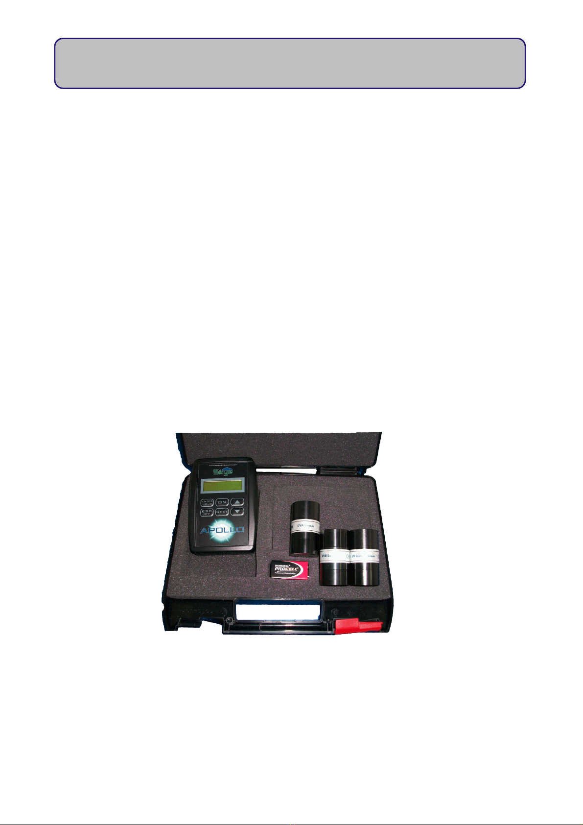
The following is a list of Skye sensors that will work with Apollo. They are all voltage output amplified
sensors.
UV-A Sensor SKU 421 Monitors the amount of UV-A (315—400nm) light that reaches Earth. Excellent for
monitoring the spectrum of UV that is useful to vitamin D production in animals.
UV-B Sensor SKU430 Monitors the amount of UV-B (280—315nm) light that reaches Earth. Excellent for
measuring the spectrum of UV that has the highgest energy, and is harmful to
animals.
UV-I Sensor SKU440 Monitors the amount of UV light that falls within the pre-determined "Erythemal"
curve. This is the portion of the UV spectrum that causes human skin to burn, and is
ideal for monitoring the potential for harm to individuals that spend a lot of time in
the sun.
AR Special SKL 2610 Monitors energy efficiency of PAR Quantum SKL 2620 plants and ecosystems.
utput proportional to levels of quanta (photons) in the ideal range 400—700nm
(near-square response).
AR Quant. SKL 2620 Monitors energy efficiency of plants and ecosystems. utput proportional to
levels of quanta (photons) in the range 400—700nm
Lux SKL 2633 Monitoring light levels in buildings, galleries, work places, animal houses, etc.
Conforms well to the CIE photopic curve.
Energy SKL 2640 Measures energy in the visible band (400—700nm).
In many cases, we are able to offer an external amplifier to convert many of Skye's sensors' output to
a range ideal for Apollo, please e-mail for more information.
17
Apollo Display Meter
Table of contents
Other Skye Measuring Instrument manuals


