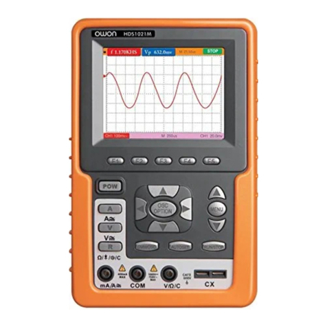
Owon HSA1000 Series User manual

HSA1000 Series
Handheld Spectrum Analyzer
User Manual
◼
HSA1016
◼
HSA1016-TG
◼
HSA1036
◼
HSA1036-TG
◼
HSA1075
◼
HSA1075-TG
Notice: -TG models are with tracking generator
For product support, visit:www.owon.com.hk/download

July 2023 edition V2.0.0
Copyright © LILLIPUT Company. All rights reserved.
The LILLIPUT's products are under the protection of the patent rights, including ones
which have already obtained the patent rights and those which are applied for. The
information in this manual will replace all materials published.
Theinformation in thismanual wascorrect at the time of printing. However, LILLIPUTwill
continue to improve products and reserves the rights to change specification at any time
without notice.
is the registered trademark of the LILLIPUT Company.
Fujian LILLIPUT Optoelectronics Technology Co., Ltd.
No. 19, Heming Road
Lantian Industrial Zone, Zhangzhou 363005 P.R. China
Tel: +86-596-2130430 Fax: +86-596-2109272
Web: www.owon.com E-mail: info@owon.com.cn

General Warranty
We warrant that the product will be free from defects in materials and
workmanship for a period of 3 years from the date of purchase of the product
by the original purchaser from our company. The warranty period for
accessories is 12 months. This warranty only applies to the original purchaser
and is not transferable to a third party.
If the product proves defective during the warranty period, we will either repair
the defective product without charge for parts and labour, or will provide a
replacement in exchange for the defective product. Parts, modules and
replacement products used by our company for warranty work may be new or
reconditioned like new. All replaced parts, modules and products become the
property of our company.
In order to obtain service under this warranty, the customer must notify our
company of the defect before the expiration of the warranty period. Customer
shall be responsible for packaging and shipping the defective product to the
designated service centre, a copy of the customers proof of purchase is also
required.
This warranty shall not apply to any defect, failure or damage caused by
improper use or improper or inadequate maintenance and care. We shall not
be obligated to furnish service under this warranty a) to repair damage
resulting from attempts by personnel other than our company representatives
to install, repair or service the product; b) to repair damage resulting from
improper use or connection to incompatible equipment; c) to repair any
damage or malfunction caused by the use of not our supplies; or d) to service
a product that has been modified or integrated with other products when the
effect of such modification or integration increases the time or difficulty of
servicing the product.
Please contact the nearest Sales and Service Offices for services.
Excepting the after-sales services provided in this summary or the
applicable warranty statements, we will not offer any guarantee for
maintenance definitely declared or hinted, including but not limited to
the implied guarantee for marketability and special-purpose
acceptability. We should not take any responsibilities for any indirect,
special or consequent damages.

i
Table of contents
List of figures.....................................................................iii
1. General Safety Requirements ........................................ 1
2. Safety Terms and Symbols............................................. 4
3. Document Overview .......................................................5
4. Quick Start ......................................................................6
4.1 General Inspection...........................................................6
4.2 Safety Precaution before Operation..............................6
4.3 First Time to Power on ....................................................7
4.4 Front Panel Overview...................................................... 9
4.5 Top Panel Overview.......................................................10
4.6 Rear Panel Overview.....................................................12
4.7 User Interface Overview................................................12
4.8 Function Keys.................................................................16
4.9 Parameter Input..............................................................19
4.10 Build-in Help..................................................................21
4.11 Touchscreen Controls..................................................21
4.12 External keyboard control...........................................25
4.13 Basic Measurement.....................................................27
5. Menu Interpretation ...................................................... 31
5.1 【FREQ】bottom softkey..........................................31
5.2 【Span】bottom softkey............................................33
5.3 【AMPTD】bottom softkey .......................................35
5.4 【Auto】bottom softkey.............................................38
5.5 【BW】bottom softkey...............................................38
5.6 【Marker】bottom softkey.........................................39
5.7 【Trace】hardkey.......................................................48
5.8 【Detector】hardkey..................................................49
5.9 【Display】hardkey....................................................52
5.10 【Sweep】hardkey...................................................53
5.11 【Trig】hardkey.........................................................54
5.12 【Source】hardkey ..................................................54
5.13 【Mode】hardkey.....................................................56
5.14 【System】hardkey..................................................60
5.15 【File】hardkey.........................................................66
5.16 【Help】hardkey.......................................................68
5.17 【Measure】hardkey................................................68

ii
6. Specification ................................................................. 73
7. Troubleshooting............................................................ 86
8. Appendix ....................................................................... 87
Appendix A: Enclosure.........................................................87
Appendix B: General Care and Cleaning..........................88
Appendix C: USB Disk Requirements...............................88
Appendix D: PC Software Requirements..........................88

iii
List of figures
Figure 4-1 Front panel............................................................... 9
Figure 4-2 Top panel .............................................................. 10
Figure 4-3 Rear panel.............................................................. 12
Figure 4-4 User interface........................................................ 13
Figure 4-5 Function softkeys.................................................. 16
Figure 4-6 Shift key and function hardkeys......................... 18
Figure 4-7 Numeric keypad.................................................... 19
Figure 4-8 The rotary knob..................................................... 20
Figure 4-9 Arrow keys ............................................................. 20
Figure 4-10 Full Span.............................................................. 28
Figure 4-11 Set frequency span............................................. 29
Figure 4-12 Set reference level.............................................. 30
List of tables
Table 4-1 AC-DC adapter requirement................................... 7
Table 5-1 Detector type comparison ............................. 50
Table 5-2 [Factory] Settings .................................................. 62

1.General Safety Requirements
1
1. General Safety Requirements
Before use, please read the following safety precautions to
avoid any possible bodily injury and to prevent this product or
any other connected products from damage. To avoid any
contingent danger, ensure this product is only used within the
ranges specified.
◼Use Proper Power Cord. Use only the power cord supplied
with the product and certified to use in your country.
◼Power Grounded. The main plug should be inserted in a
power socket outlet only if provided with a protective earth
contact.
◼Check all Terminal Ratings. To avoid fire or shock hazard,
check all ratings and markings on this product. Refer to the
user manual for more information about ratings before
connecting to the instrument.
◼Use Proper Overvoltage Protection. Make sure that no
overvoltage (such as that caused by a thunderstorm) can
reach the product, or else the operator might expose to danger
of electrical shock.
◼Do not operate without covers. Do not operate the
instrument with covers or panels removed.
◼Avoid exposed circuit. Be careful when working on exposed
circuitry to avoid risk of electric shock or other injury.
◼Do not operate if any damage. If you suspect damage to the
instrument, have it inspected by qualified service personnel
before further use. Any maintenance, adjustment or
replacement especially to circuits or accessories must be
performed by qualified service personnel.
◼Use your instrument in a well-ventilated area. Make sure
the instrument installed with proper ventilation.
◼Do not operate in damp conditions. In order to avoid short
circuiting to the interior of the device or electric shock, please

1.General Safety Requirements
2
do not operate in a humid environment.
◼Do not operate in an explosive atmosphere. In order to
avoid damages to the device or personal injuries, it is
important to operate the device away from an explosive
atmosphere.
◼Keep product surfaces clean and dry. To avoid the influence
of dust or moisture in air, please keep the surface of device
clean and dry.
◼Electrostatic Prevention. Operate the instrument in an
electrostatic discharge protective environment to avoid
damage induced by static discharges. Always ground both the
internal and external conductors of cables to release static
before making connections.
◼Protect the Input Terminals of Instrument. Do not bend or
hit the input terminals and the connected devices, (such as
filter, attenuator, etc.) as such stress may cause damages to
devices and the instrument. Do not mix the use of 50Ω and
75Ω connectors and/or cables.
◼Do Not Overload the Input. To avoid damaging the
instrument, the signals at input terminal must be less than 50V
DC voltage components and 30 dBm (1 W) AC (RF)
components.
◼Appropriate Use of Power Meter. If you are not sure of the
characteristics of signal under measure, follow these
recommendations to ensure safe operations: if a RF power
meter is available, use it to measure the power level of this
signal first; or add a rated external attenuator between signal
cable and input terminal of the instrument. Maximum
attenuation, reference level and maximum span frequency
should be selected, to make the signals displayed within the
screen.
◼Know About the Specification Conditions of the
Instrument. For maximum performance of the instrument, use
the analyzer under specified conditions.

1.General Safety Requirements
3
◼Handling Safety. Please handle with care during
transportation to avoid damages to buttons, knob, interfaces
and other parts on the panels.

2.Safety Terms and Symbols
4
2. Safety Terms and Symbols
Safety Terms
Terms in this manual (The following terms may appear in this
manual):
!
WARNING
Warning indicates conditions or practices that could result
in injury or loss of life.
Terms on the product (The following terms may appear on this
product):
DANGER
Indicates an immediate hazard or injury possibility.
WARNING
Indicates a possible hazard or injury.
CAUTION
Indicates potential damage to the instrument or other
property.
Symbols on the product (The following symbols may appear on
the product):
!
Refer to Manual
Conforms to European Union directives
This product complies with the WEEE Directive
(2002/96/EC) marking equipment. The affixed product
label indicates that you must not discard this
electrical/electronic product in
domestic household waste.
!
CAUTION
Caution indicates the conditions or practices that could
result in damage to this product or other property.

3.Document Overview
5
3. Document Overview
⚫Quick Start
This chapter states the matters need to attention before first
power on, how to power on at first time, introduces spectrum
analyzer’s front/rear panel and user interface, explains how to
use the instrument with a measurement example
demonstration.
⚫Menu Interpretation
This chapter offers spectrum analyzer’s front panel menu and
button interpretation.
⚫Specification
This chapter lists spectrum analyzer’s specification parameter.
⚫Trouble Shooting
This chapter helps to implement the troubleshooting and deal
with after sale repair.
⚫Appendix
This chapter introduces accessories of spectrum analyzer and
how to maintain device.
Convention on button and menu key format:
Button character + bold bracket, e.g. 【FREQ】stands for FREQ
bottom softkey.
Submenu words+bracket, e.g.[Center frequency] stands for
【FREQ】function’s center frequency item, that is common called
softkey menu item.
Related document:
Related documents including: Quick guide, User manual,
programme guide and etc.

4.Quick Start
6
4. Quick Start
This chapter states the matters need to attention before first power
on, and how to power on at first time, introduces spectrum
analyzer’s front/top panel and user interface, explains how to use
the instrument with a measurement example demonstration.
4.1 General Inspection
When you receive your new instrument, it is recommended
that you check the instrument following these steps:
1.Check for transportation damage.
If it is found that the packaging carton or the foamed plastic
protection cushion has suffered serious damage, do not throw
it away until the complete device and its accessories have
been electrically and mechanically checked.
2.Check the Accessories
The supplied accessories are described in the "Appendix A:
Enclosure" of this Manual. Please ensure that all the listed
accessories are present and undamaged, if any problems are
found please contact your distributor or our local office.
3.Check the Complete Instrument
If there is any physical damage, operational fault, or
performance issue please contact your distributor or our local
office. If there is any damage to the instrument please ensure
you keep the original packaging. Ideally you should always
keep the original packaging if the instrument must be returned
for repair.
4.2 Safety Precaution before Operation
4.2.1 Power Supply Requirements
The analyzer allows the use of either an internal lithium battery
pack, or AC-DC adapter shipped with the analyzer for its power
supply.
The lithium battery is 7.4V, 9100 mAh.
The table below lists the requirement of the AC-DC adapter.

4.Quick Start
7
Table 4-1 AC-DC adapter requirement
AC-DC adapter parameter
Compatible range
Input Voltage
100 V - 240 VAC, 50/60 Hz
Output Voltage
12 - 15 VDC
Max. Power
45 W
4.2.2 Electro-static Discharge (ESD) Protection
ESD is an issue often ignored by users. Damage from ESD on the
instrument is unlikely to occur immediately but will significantly
reduce the reliability of it. Therefore, ESD precautions should be
implemented in the work environment, and applied daily.
Generally, there are two steps to manage ESD protection:
1) Conductive table mat to connect hands via wrist bands
2) Conductive ground mat to connect feet via ankle straps
Implement both protection methods will provide a good level of
anti-static protection. If used alone, the protection will not be as
reliable. To ensure user’s safety, anti-static components should
offer at least 1MΩ isolation resistance.
Make good use of anti-static technology to protect components
from damage:
1) Quickly ground the internal and external conductor of the coaxial
cable before it is connected to the spectrum analyzer.
2) Staff must wear anti-static gloves before touching the connector
cord or doing any assemble work.
3) Assure all the instruments are grounded properly to avoid static
storage.
4.3 First Time to Power on
Note: Keep the air vents always clear of obstructions for proper
!
WARNING
The above ESD protections measures cannot be used
when working with over 500V!

4.Quick Start
8
ventilation and cooling of the instrument.
!
CAUTION
Use only the original AC-DC adapter or originally supplied
battery for the power source.
The maximum RF input level of an average continuous
power is 30 dBm (or 50 VDC signal input). Avoid connecting
a signal into the analyzer that exceeds the maximum level.
1) Press the power switch on the front panel.
2) Self-initialization takes about 30 seconds, after the boot screen
the spectrum analyzer will default to the scanning curve.
3) After power on, let the spectrum analyzer warm up for 30
minutes for stabilization to obtain the most accurate results.

4.Quick Start
9
4.4 Front Panel Overview
10
1 3 4
6
5
7
8
9
2
Figure 4-1 Front panel
NO.
Description
①
LCD touchscreen.
②
Light Sensor: Adjusts the screen backlight according to
the environmental light. This state can be specified in
【Display】→ [Brightness].
③
Power key: Long push to turn on the analyzer, push to turn
on/off the LCD display, long push to turn off the analyzer.
④
Preset key: Resets the analyzer to a known state.
This state can be specified in 【System】→
[PowerOn/Preset>] → [Preset>].
⑤
Arrow keys.
⑥
Rotary knob.

4.Quick Start
10
4.5 Top Panel Overview
12 3 4
11 10 9 8756
Figure 4-2 Top panel
NO.
Name
Description
①
GEN Output
connector
(50 Ω)
N type female connector. The output for
the built-in tracking generator.
②
10MHz
IN/OUT
BNC, female connector. The BNC input or
output of the 10 MHz reference clock.
③
EXT Trig In
connector
BNC, female connector. Connects to an
external TTL signal. The TTL signal is used
to trigger the analyzer’s internal sweep.
⑦
Shift key: Press the Shift key to active it, the light is on.
When the Shift key is active, pressing a number key will
execute the upper function.
Long press the Shift key to active it persistently. To switch
to the brief active status, short press the Shift key.
⑧
Backspace key: Deletes the last character from input.
⑨
Enter key: Confirms a parameter selection or
configuration.
⑩
Function / numeric keypad.

4.Quick Start
11
④
RF Input
connector
(50 Ω)
N type female connector. Connector for RF
input.
!
CAUTION
Input voltage at RF input port must not be higher
than 50 V DC to avoid damage to the attenuator
and input mixer tracking generator.
When input attenuator is higher than 10 dB, the
RF port input signal must be less than +30 dBm.
⑤
External power
connector
Provides input for the DC power source via
an AC-DC adapter.
⑥
LED indicator
Green light when external DC power is
connected. Red light when the battery is
charging. Blinking light when charge
suspend or battery absent.
⑦
GPS/BDS
antenna
connector
SMA-female type. Connects an GPS/BDS
Antenna to offer the GPS location for the
field testing. Active antenna supported.
⑧
USB Device
interface
MICRO-USB type. Connects to a PC. This
USB interface supports PictBridge printer
and remote-control connection.
⑨
LAN interface
Through this interface, the analyzer can be
connected to your local network for remote
control.
⑩
Mouse
keyboard and
other USB
device
interface
Type A. Connects to a USB memory stick.
⑪
Headphone
jack
Insert the headset to listen to the sound
after signal demodulation.

4.Quick Start
12
4.6 Rear Panel Overview
13
2
2
Figure 4-3 Rear panel
NO.
Name
①
Battery compartment
②
Air vents
③
Tilt stand
4.7 User Interface Overview
Figure below illustrates the user interface, with touch screen menu
keys, top bar, and measurement settings and results around the
graph area.

4.Quick Start
13
123 4 5 6 7 8 9 10 11 12 13 1514
16
17
19
18
20
21
22
23
24
25
27
30 26
29 28
35
34
33
32
31
Figure 4-4 User interface
NO.
Name
Description
Related Key
①
External
reference
Set the reference
frequency as Int (internal)
or Ext (external) input.
FREQ →
[Freq Ref]
②
Preamplifier
Turn on/off the
preamplifier.
AMPTD→
[Preamplifier]
③
Sweep status
Set the sweep status to
Single or Cont
(continuous).
【Sweep】→
[Sweep
Single] or
[Sweep Cont]
④
Source
Show the source type as
CW (Continuous Wave) or
TG (Tracking Generator),
press to turn on/off the
source output.
【Source】→
[Output] and
[Source GEN]

4.Quick Start
14
⑤
Trigger type
Set the trigger type to
Auto, Video, Pos
(external positive edge),
Neg (external negative
edge).
【Trig】
⑥
Continuous
peak search
Open/close continuous
peak search.
【Marker】→
[Peak>]
⑦
Automatic
search
In automatic search
mode.
【Auto】
⑧
USB sign
USB access mark.
⑨
Audio
demodulation
Open audio
demodulation.
【Mode】→
[Modulation>]
⑩
Remote
control
In remote control mode.
⑪
FFT mode
When the resolution
bandwidth is set to less
than 3kHz, it is
automatically transferred
to FFT mode.
⑫
LAN interface
communicatio
n sign
LAN internet interface
communication sign.
⑬
UNCAL sign
Measurements not
calibrated.
⑭
Date/Time
Display system
Date/Time,click to call
the modify date screen.
【System】
→[Setting>]
→[Date/Time
>]
⑮
Menu title
The current menu belongs
to the function, click to call
out the shortcut menu.
⑯
Marker value
Display current marker
value and amplitude
value(when zero sweep is
time ).When marker
function open,display
respond marker value.
【Marker】
Other manuals for HSA1000 Series
1
This manual suits for next models
6
Table of contents
Other Owon Measuring Instrument manuals

Owon
Owon XSA1000 Series User manual

Owon
Owon PC311-TY User manual

Owon
Owon PC321 User manual

Owon
Owon PC321-TY User manual

Owon
Owon HSA1000 Series User manual

Owon
Owon CM2100 User manual

Owon
Owon XDM Series User manual

Owon
Owon XSA800 Series User manual

Owon
Owon CM240 User manual

Owon
Owon Lilliput HDS2062M User manual
Popular Measuring Instrument manuals by other brands

Arkray
Arkray PocketChem UA operating manual

TFA
TFA 30.5050.01 instruction manual

MEWOI
MEWOI 8000 quick start guide

Hornady
Hornady LOCK-N-LOAD BLACKPOWDER Product instructions

Endress+Hauser
Endress+Hauser Memocheck Sim CYP03D operating instructions

Hanna Instruments
Hanna Instruments HI 93709 instruction manual