Skypatrol ST8050 User manual

ST8050
User Guide
Revision 2.00
5/4/2013
Confidential and Proprietary Information – © 2013 Skypatrol, LLC.
Do not duplicate without express permission from Skypatrol, LLC
ST8050
User Guide
ST8050UG001

General
All efforts have been made to ensure the accuracy of material provided in this document at the time
of release. However, the items described in this document are subject to continuous development
and improvement. All specifications are subject to change without notice and do not represent a
commitment on the part of SkyPatrol LLC. SkyPatrol LLC., will not be responsible for any loss or
damages incurred related to the use of information contained in this document.
This product is not intended for use in life support appliances, devices or systems where a
malfunction of the product can reasonably be expected to result in personal injury. SkyPatrol LLC.,
customers using, integrating, and/or selling this product for use in such applications do so at their
own risk and agree to fully indemnify SkyPatrol LLC., for any damages resulting from illegal use or
resale.
Copyright
Complying with all applicable copyright laws is the responsibility of the user. Without limiting the
rights under copyright, no part of this document may be reproduced, stored in or introduced into a
retrieval system, or transmitted in any form or by any means (electronic, mechanical, photocopying,
recording or otherwise), or forany purpose, without theexpress written permission of SkyPatrol LLC.
SkyPatrol may have patents, patent applications, trademarks, copyrights or other intellectual
property rights covering subject matter in this document. Except as expressly provided in any
written license agreement from SkyPatrol, the furnishing of this document does not give you any
license to these patents, trademarks, copyrights or other intellectual property.
©2013, SkyPatrol LLC. All rights reserved.
SkyPatrol, the SkyPatrol logo are trademarks or registered trademarks of SkyPatrol LLC.

User Guide to ST8050
ST8050UG001 – User Guide 1 Revision 2.0
Warranty Information
LIMITED WARRANTY
SkyPatrol, LLC., (Skypatrol) warrants to the original purchaser of the product that, for a period of one
(1) year from the date of product purchase, the product hardware, when used in conjunction with
any associated software (including any firmware and applications such as the modem manager)
supplied by SkyPatrol, will be free from defects in material or workmanship under normal operation.
SkyPatrol further warrants to such original purchaser that, for a period of ninety (90) days from the
date of product purchase, any software associated with the product will perform substantially in
accordance with the user documentation provided by SkyPatrol, and any software media provided
with the product will be free from defects in material or workmanship under normal operation.
SkyPatrol does not warrant that the product hardware or any associated software will meet the
purchaser’s requirements or that the operation of the product hardware or software will be
uninterrupted or error-free. This limited warranty is only for the benefit of the original purchaser
and is not transferable.
During the warranty period applicable to the product hardware, SkyPatrol, at its expense and in its
sole discretion, will repair or replace the product if it is determined to have a covered hardware
defect, provided that the purchaser first notifies SkyPatrol of any such defect, furnishes SkyPatrol
with a proof of purchase, requests and obtains a return merchandize authorization (RMA) number
from SkyPatrol, and returns the product, shipping charges prepaid, to SkyPatrol under that RMA. If,
upon reasonable examination of the returned product, SkyPatrol does not substantiate the defect
claimed by purchaser, or determines that the defect is not covered under this limited warranty,
SkyPatrol will not berequired to repair or replace the product, but may instead reship the product to
the purchaser, in which case purchaser shall be responsible for paying SkyPatrol’s usual charges for
unpacking, testing, and repacking the product for reshipment to purchaser. Purchaser shall bear the
risk of loss or damage in transit to any product returned by purchaser to SkyPatrol, or any returned
product not found to be defective or covered under this warranty and reshipped by SkyPatrol to
purchaser. In the event SkyPatrol repairs or replaces a defective product, the repaired or
replacement product will be warranted for the remainder of the original warranty period on the
defective product. If SkyPatrol is unable to repair or replace a defective product, the purchaser’s
exclusive remedy shall be a refund of the original purchase price. Any returned and replaced
product, or any product for which SkyPatrol has refunded the original purchase price, becomes the
property of SkyPatrol.
During the warranty period applicable to the software or its media, SkyPatrol, at its expense, will
replace any defective software or media if purchaser gives written notification of the defect to the
technical support department at SkyPatrol during the applicable warranty period. SkyPatrol shall not
have any obligation to provide any software bug fixes, upgrades or new releases except as necessary
to correct any covered defect of which purchaser notifies SkyPatrol during the applicable warranty
period.
SkyPatrol shall have no obligation under this limited warranty for (a) normal wear and tear, (b) the
cost of procurement of substitute products or (c) for any defect that is (i) discovered by purchaser
during the warranty period but purchaser does not notify or request an RMA number from
SkyPatrol, as required above, until after the end of the warranty period, (ii) caused by any accident,
misuse, abuse, improper installation, handling or testing, or unauthorized repair or modification of
the product, (iii) caused by use of any software other than any software supplied by SkyPatrol, or by

User Guide to ST8050
ST8050UG001 – User Guide 2 Revision 2.0
use of the product other than in accordance with its documentation or (iv) the result of electrostatic
discharge, electrical surge, fire, flood or similar causes.
SKYPATROL’S SOLE RESPONSIBILITY AND PURCHASER’S SOLE REMEDY UNDER THIS LIMITED
WARRANTY SHALL BE TO REPAIR OR REPLACE THE PRODUCT HARDWARE, SOFTWARE OR SOFTWARE
MEDIA (OR IF REPAIR OR REPLACEMENT IS NOT POSSIBLE, OBTAIN A REFUND OF THE PURCHASE
PRICE) AS PROVIDED ABOVE. SKYPATROL EXPRESSLY DISCLAIMS ALL OTHER WARRANTIES OF ANY
KIND, EXPRESS OR IMPLIED, INCLUDING WITHOUT LIMITATION THE IMPLIED WARRANTIES OF NON-
INFRINGEMENT, MERCHANTABILITY, SATISFACTORY PERFORMANCE AND FITNESS FOR A
PARTICULAR PURPOSE. IN NO EVENT SHALL SKYPATROL BE LIABLE FOR ANY INDIRECT, SPECIAL,
EXEMPLARY, INCIDENTAL OR CONSEQUENTIAL DAMAGES (INCLUDING WITHOUT LIMITATION LOSS
OR INTERRUPTION OF USE, DATA, REVENUES OR PROFITS) RESULTING FROM A BREACH OF THIS
WARRANTY OR BASED ON ANY OTHER LEGAL THEORY, EVEN IF SKYPATROL HAS BEEN ADVISED OF
THE POSSIBILITY OR LIKELIHOOD OF SUCH DAMAGES.
Some jurisdictions may require a longer warranty period than specified above and, accordingly, for
products sold in those jurisdictions the applicable warranty period shall be extended as required
under the law of those jurisdictions. Furthermore, some jurisdictions may not allow the disclaimer
of implied warranties or the exclusion or limitation of incidental or consequential damages, so the
above disclaimer, limitation or exclusion may not apply to products sold in those jurisdictions. This
limited warranty gives the purchaser specific legal rights and the purchaser may have other legal
rights which vary from jurisdiction to jurisdiction.
In some instances, the product may also be covered by another limited warranty contained in a
separate written agreement between SkyPatrol and the distributor or reseller, if any, from whom
purchaser purchased the product. That other limited warranty may provide, for example, a longer
warranty period or a different product return procedure that may also be available to purchaser.
This limited warranty shall be governed by the laws of the State of Texas, United States of America,
without regard to conflict of laws principles. This limited warranty shall not be governed in any
respect by the United Nations Convention on Contracts for the International Sale of Goods.

User Guide to ST8050
ST8050UG001 – User Guide 3 Revision 2.0
Table of Contents
1INTRODUCTION...............................................................................................................1
1.1 Overview........................................................................................................................... 1
1.2 Scope................................................................................................................................ 1
1.3 Related documents........................................................................................................... 1
2QUICK START GUIDE........................................................................................................2
2.1 Connecting the modem..................................................................................................... 2
2.1.1 ST8050...................................................................................................................................2
2.1.1.1 Inserting the SIM card...................................................................................................................... 4
2.2 Serial port connections......................................................................................................5
2.3 Device setup..................................................................................................................... 5
2.3.1 GRPS configuration................................................................................................................5
2.3.2 Periodic report configuration...................................................................................................6
2.3.3 IO alarms................................................................................................................................7
2.4 Downloading code to the modem...................................................................................... 8
2.4.1 SKYPATROL Configuration Tool (SCT) ..................................................................................9
2.4.1.1 Downloading foundation code........................................................................................................... 9
2.4.1.2 Downloading application code ........................................................................................................ 11
2.4.2 Downloading.........................................................................................................................11
2.5 Provisioning and activation..............................................................................................12
2.6 Configuration Parameters ...............................................................................................13
2.6.1 GRPS configuration..............................................................................................................13
2.6.2 Periodic report configuration.................................................................................................13
2.6.3 IO alarms..............................................................................................................................15
3ANTENNA SETUP...........................................................................................................17
3.1 Antenna recommendations .............................................................................................17
3.1.1 GPS .....................................................................................................................................17
3.1.2 Iridium..................................................................................................................................17
3.1.3 GSM/GPRS..........................................................................................................................17
3.2 Grounding.......................................................................................................................17
3.3 Noise problems...............................................................................................................19
4ACTIVATING AND PROVISIONING THE MODEM...............................................................20
4.1 GPRS..............................................................................................................................20
4.1.1 Activation..............................................................................................................................20
4.2 Iridium.............................................................................................................................20
4.2.1 Activation..............................................................................................................................20
4.2.2 Provisioning..........................................................................................................................20
5NETWORKS...................................................................................................................22
5.1 Iridium.............................................................................................................................22
5.1.1.1 Sequence of events: Mobile Originated–Short Burst Data message (MO-SBD)................................... 22
5.1.1.2 Sequence of events: Mobile Terminated–Short Burst Data message (MT-SBD)............................... 23
5.2 GSM................................................................................................................................23
APPENDIX A – GLOSSARY OF TERMS.....................................................................................24
APPENDIX B – ST8050 CONNECTOR DESCRIPTION..................................................................26

User Guide to ST8050
ST8050UG001 – User Guide 4 Revision 2.0
List of Figures
Figure 2-1: ST8050 assembly data cable....................................................................................................2
Figure 2-2: ST8050 assembly data cable components................................................................................2
Figure 2-3: ST8050 locking connector.........................................................................................................3
Figure 2-4: ST8050 antenna connections....................................................................................................3
Figure 2-5: SCT – Initial screen...................................................................................................................9
Figure 2-6: SCT – Update the firmware (1)................................................................................................10
Figure 2-7: SCT – Update the firmware (2)................................................................................................10
Figure 2-5: SCT – Update the firmware (3)................................................................................................10
Figure 2-9: Completion of successful download (using SCT).....................................................................11
Figure 2-10: SCT – Update Application (1)................................................................................................11
Figure 2-11: SCT – Update Application (2)................................................................................................12
Figure 2-6: Completion of successful download (using SCT).....................................................................12
Figure 3-1: Antennas with blocked view of sky..........................................................................................18
Figure 3-2: Tipped over antenna...............................................................................................................18
Figure 3-3: Noise - radiated and conducted...............................................................................................19
Figure 5-1: Iridium network diagram..........................................................................................................22

User Guide to ST8050
ST8050UG001 – User Guide 1 Revision 2.0
1Introduction
1.1 Overview
The SKYPATROL ST8050 is a highly configurable, dual mode solution that is ready for global use. The
ST8050 is designed to communicate with terrestrial GSM cellular network systems when a cellular
signal is available, and to slide seamlessly into its back-up mode to communicate with a satellite
system when a cellular signal is not available. The ST8050 has additional processing power, memory,
and input/outputs that allow sophisticated customer applications to runwithin the modem.
1.2 Scope
This document covers the key features of the ST8050, a description of the operating environment,
instructions for setting up the modem including the installation and downloading of ‘C’ code, as well
as an overview of the software architecture of the ST8050 modem. This interface allows
programmers to prepare custom ‘C’ code applications. With use of the tools included in the API
development environment, these applications can be embedded in the modem to take maximum
advantage of the power and functionality of SKYPATROL products.
This manual is divided into 5 chapters and 1 appendix, which aresummarized below:
Chapter 1: INTRODUCTION to the ST8050 modem contains the scope of the document, a list of
related documents and information for contacting SKYPATROL.
Chapter 2: QUICK START GUIDE explains how to set up the modem, activate and provision it.
Chapter 3: ANTENNA SET UP describes how to set up the satellite and GSM/GPRS antennas for
the best possible reception.
Chapter 4: ACTIVATING AND PROVISIONING THE MODEM discusses how to set up the
connections between the modem and the satellite and terrestrial networks.
Chapter 5: NETWORK describes the Networks used by the device to transmit the messages.
Appendix A - Glossary of terms
Appendix B - ST8050 Connector Description
CONFIDENTIALITY OBLIGATIONS
1.3 Related documents
The following documents contain valuable information:
[1] ST8050AT001 - SkyPatrol AT Command
[2] ST8050UG002 - SKYPATROL Configuration Tool (SCT)
User Guide to ST8050
ST8050UG001 – User Guide 2 Revision 2.0
2Quick Start Guide
The ST8050 operates from 6VDC to 32VDC. For satellite applications, optimal performance requires
at least 10.5 VDC.
In order to communicate with the ST8050 the following is required:
-a computer with at least one available serial port or aUSB-to-serial adapter (Keyspan, part
number USA-19HS)
-a power supply capable of providing at least 3 amps at 12 V
-a ST8050 data cable
-an ST8050 modem.
2.1 Connecting the modem
2.1.1 ST8050
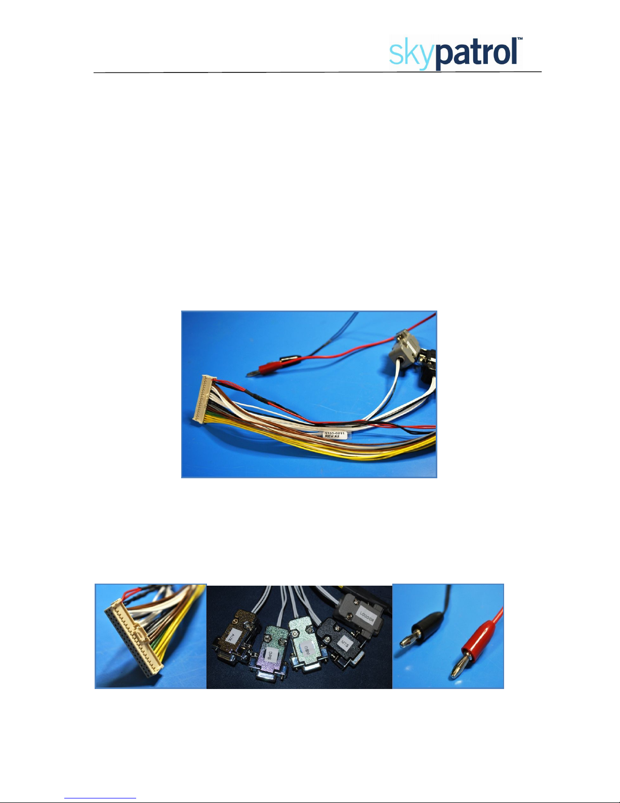
The SKYPATROL part number forthe ST8050 assembly data cable is CBL092.
Figure 2-1: ST8050 assembly data cable
There are three main components of the ST8050 assembly data cable:
1. the locking connector
2. five serial DB9 connectors for use with the Logger port, MTS, AUX, GPS and GSM)
3. Power (red) and ground (black).
Figure 2-2: ST8050 assembly data cable components

User Guide to ST8050
ST8050UG001 – User Guide 3 Revision 2.0
Plug the locking connector into the modem. The connector can only fit one way as shown below.
Figure 2-3: ST8050 locking connector
On the opposite side of the modem, attach the antenna cable to the appropriate connector (Figure
2-4).
Figure 2-4: ST8050 antenna connections
Additional serial connections, I/O, and other signal lines are also available
as non-terminated wires that come shrink-wrapped together in the assembly
cable.

User Guide to ST8050
ST8050UG001 – User Guide 4 Revision 2.0
2.1.1.1 Inserting the SIM card
One of two types of screw is used to attach the SIM card to the modem. The screw will be a round
head screw, Phillips, 0-80 X 3/16, SS, or a hex screw, size 0-80, 50th.
1. Find side of case with screw and washers. 2. Remove screw and washers from side of case
3. Insert SIM card with the metal contacts
facing upward.
4. Ensure SIM card clicks into place.
5. Replace the washers and screw.

User Guide to ST8050
ST8050UG001 – User Guide 5 Revision 2.0
2.2 Serial port connections
There are two ports that come terminated with DB9 connectors:
1. the Logger port - provides diagnostic data for the user
2. the MTS port - implements SKYPATROL’s Communication Protocol (QCP)
2.3 Device setup
There are a number of parameters that may be configured as part of the application code. These
parameterscontrol the periodic reporting time, IO alarms, Analog alarms, speed alerts and other
modem functions.
Those parameters are setup in the device via AT commands, using the MST port. When connecting
to the MTS port, the default settings are:
Baud rate: 57600bps
Data bits: 8
Parity: None
Stop bits: 1
Flow control: None
2.3.1 GRPS configuration
TheST8050 uses the GRPS network or Iridium network (ifGPRS is not available) to send the
message.
Use AT&STGPRS command to setup all parameters related with the GPRS network.
AT&STGPRS=<apn>,<user>,<password>,<protocol>,<ip>, <port>
<apn> GPRS APN provided by the telecom operator
<user> GPRS username provided by the telecom operator
<password>
GPRS password provided by the telecom operator
<protocol> Transport protocol used to communicate with the server.
0: TCP
1: UDP
<ip> The server hostname or IP address.
Ex.: xyz.com or 000.000.000.000
<port> The server port which the ST8050 must connect.
Example: AT&STGPRS=proxy,,,1,10.0.0.10,1730

User Guide to ST8050
ST8050UG001 – User Guide 6 Revision 2.0
2.3.2 Periodic report configuration
The ST8050 will send messages, depending on message format, using GRPS network or Iridium
network. The periodic report timers are defined bases in the state of IO 1 (ignition).
Use AT&STREPORT command to setup those timers
AT&STREPORT=<mode>,<format>, <GPRS mask>, <Iridium mask>, <GPRS timeOn>, < GPRS time
Off>, <Iridium time ON>, <Iridium time Off>, <GPRS distance>, <Iridium distance>
<mode> Report mode, indicateswhat condition must be used to
report:
0: Time condition
1: Distance condition
2: Time or distance condition
<format> Indicates how the protocol must be formatted to be
transmitted.
0: Binary
1: ASCII
<GPRS mask> Indicates which parameters willbe embedded in the
report, this parameter is a numerical value in which each
bit represents a parameter as indicated by the following bit
mask:
Bit 0 – Location Data
Bit 1 – Digital Port Status
Bit 2 –Analog Ports Value
Bit 3 – GSM Strength
Bit 4 – Iridium Strength
Bit 5 – GSM Network Information
Bit 6 – GSM SIMCARD information
Bit 7 – Used by the ST8050 to indicate that an alarm was
triggered.
<Iridium mask> Same as GPRS Mask
<GPRS time On> This parameter indicates the time interval in seconds that
the unit must report if the Digital port 1 level is high and
the GPRS modem has signal.
0 – Disable the report in this condition.
Range: 20 to 65535 seconds

User Guide to ST8050
ST8050UG001 – User Guide 7 Revision 2.0
<GPRS time
Off> Thisparameter indicates the time interval in seconds that
the unit must report if the Digital port 1level is low and the
GPRS modem has signal.
0 – Disable the report in this condition.
Range: 20 to 65535 seconds
<Iridium time
On> This parameter indicates the time interval in seconds that
the unit must report if the Digital port 1 level is high and
the GPRS modem has no signal or is disabled.
0 – Disable the report in this condition.
Range: 60 – 65535 seconds
<Iridium time
Off> Thisparameter indicates the time interval in seconds that
the unit must report if the Digital port 1 level is low and the
GPRS modem has no signal or isdisabled.
0 – Disable the report in this condition.
Range: 60 – 65535 seconds
<GPRS
distance> Thisparameter indicates the distance interval in meters
that the unit must move before report.
0 – Disable the report in this condition.
Range: 0– 65535 x100 meters
<Iridium
distance> Thisparameter indicates the distance interval in meters
that the unit must move before reporting.
0 – Disable the report in this condition.
Range: 0– 65535 x100 meters
Example: The device will report by GPRS every 5 minutes when the ignition is ON, every 1
hour when ignition is OFF and it will report by Iridium every 15 minutes when the ignition is
ON, every 4 hours when ignition is OFF
AT&STREPORT=0,1,127,127,300,3600,900,14400,0,0
2.3.3 IO alarms
The ST8050 uses the IO alarms to notify the end user of all events which are triggered by external
sensors connected to the device. IO alarms can beused forignition, open doors,panic buttons, etc.
TheAT&STDIOALARM command to setup all IO alarms
AT&STDIOALARM=<port id>,<trigger type>, <condition>, <min duration>
Port ID Id of the port where the trigger will be created.
Range: 1 to 8
User Guide to ST8050
ST8050UG001 – User Guide 8 Revision 2.0
Trigger Type Define the type of the trigger
0: Disable
1: Report immediately after the condition is met.
2: Execute a time counter while the condition is met.
Condition Define the condition to trigger the alarm.
0: When the port level goes UP.
1: When the port level goes DOWN.
2: When the port level changes, UP or DOWN, this condition is
not valid if the trigger type is 2.
Minimum
duration Indicates the time that the condition must be in valid state
before trigger the alarm. Value in seconds.
Range: 0 to 255
Example: AT&STIOALARM=1,1,2,2
2.4 Downloading code to the modem
The ST8050 uses two separate code packages: the foundation and the application. The foundation
and application are supplied by Skypatrol. Either can be loaded into the modem using the
SKYPATROL Configuration Tool (SCT).
The application code package is a loadable software file that may or may not be present in the
modem. If this fileis not present, the modem acts as a simple satellite or GPRS/GSM modem that is
controlled externally via a serial interface. Alternatively,for more complex applications a developer
can create a custom application in C code to be embedded in the modem.
The foundation code package consists of code to implement the Session, Transport and Network
layers of the satellite/terrestrial protocol. The application and the foundation are independent tasks
within the modem. The application sends and receives messages to and from the foundation, and
the foundation sends and receives messages over the RF or GPRS/GSM links.
The modem is loaded with foundation code when it leaves the factory. New foundation code may
be obtained from the SkyPatrol’s ftp at ftp://ftp.skypatrol.com, using the user’s assigned username
and password.
If the software developer writes a custom application that will be loaded into the
modem by SKYPATROL’s production line, it is imperative to ensure that the
application sets any of the parameters associated with baud rates and power-
down modes during boot up.
User Guide to ST8050
ST8050UG001 – User Guide 9 Revision 2.0
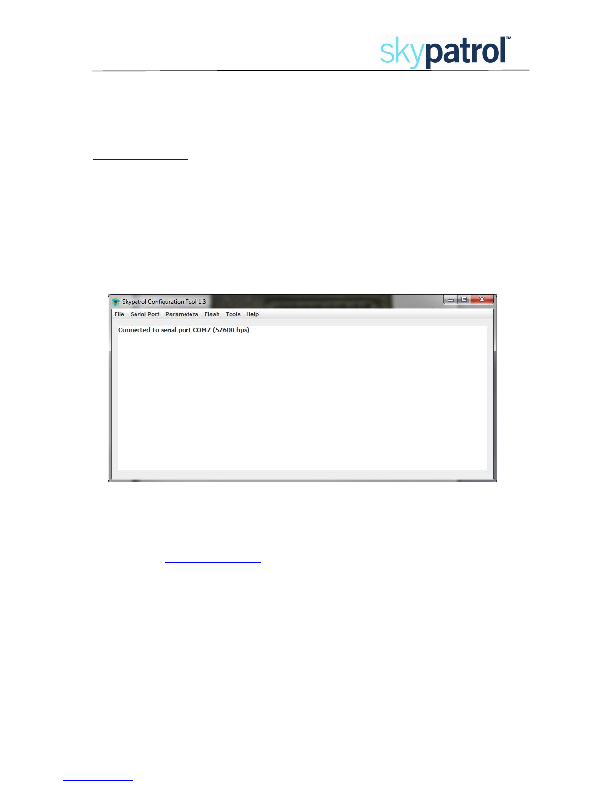
2.4.1 SKYPATROL Configuration Tool (SCT)
The SKYPATROL Configuration Tool (SCT) provides a Graphical User Interface (GUI) to download code
and modify configuration parameters in the modem. SCTis availableon the SkyPatrol’s ftp at
ftp://ftp.skypatrol.com.
To download code or modify configuration parameters, firstload and run SCT ona PCconnected to
the modem’s MTS serial port. When connecting to the MTS port, the default settings are:
Baud rate: 57600bps
Data bits: 8
Parity: None
Stop bits: 1
Flow control: None
Figure 2-5: SCT – Initial screen
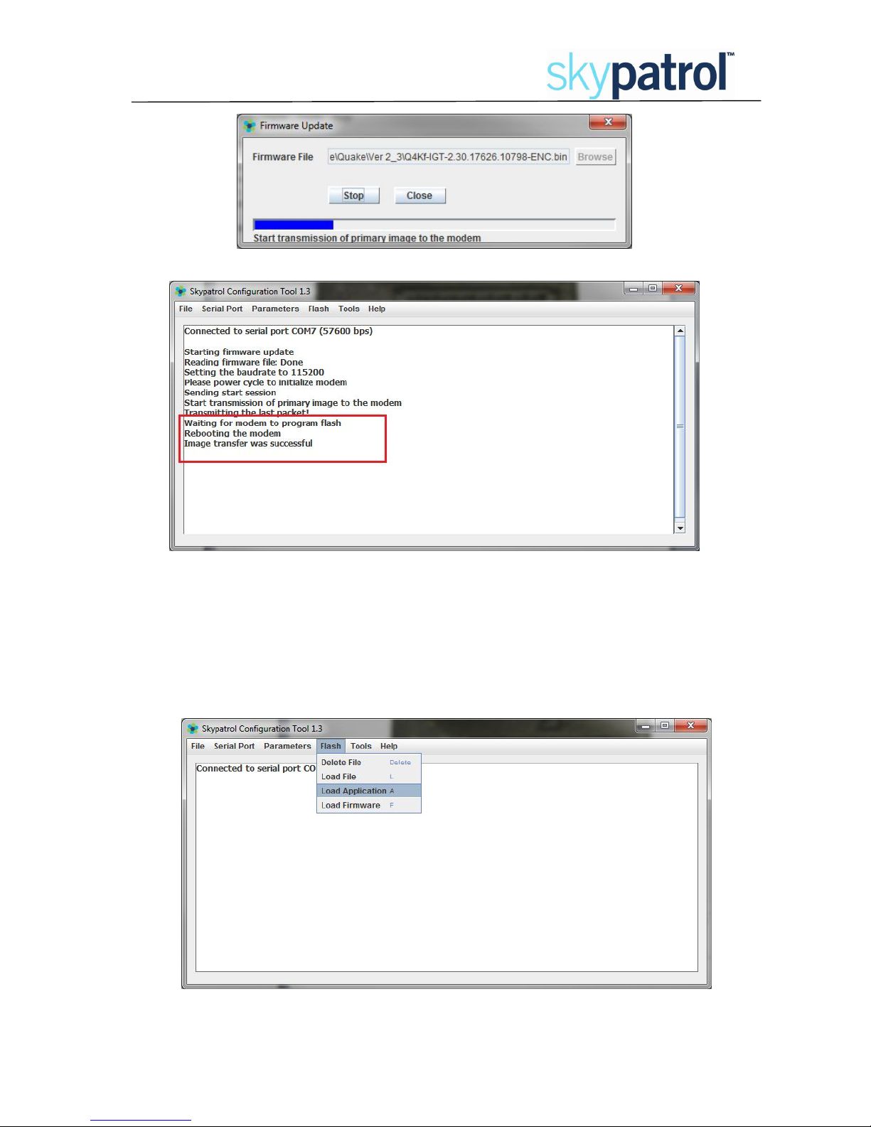
2.4.1.1 Downloading foundation code
If it is necessary to update the foundation (firmware) code, download the zip file from the
SkyPatrol’s ftp atftp://ftp.skypatrol.com. After unzipping the file, there should be a foundation file
with the name format of Q4Kf-xGT-n.n.nnnn.nnn-ENC.bin.
1. In SCT, select Flash Load Firmware

User Guide to ST8050
ST8050UG001 – User Guide 10 Revision 2.0
Figure 2-6: SCT –Update the firmware (1)
2. Enter the foundation file’s address and select .
Figure 2-7: SCT –Update the firmware (2)
3. SCT starts the firmware update. Power cycle the modem.
Figure 2-5: SCT –Update the firmware (3)
4. The progress bar will indicate when the file is loaded.
User Guide to ST8050
ST8050UG001 – User Guide 11 Revision 2.0
Figure 2-9: Completion of successful download (using SCT)
2.4.1.2 Downloading application code
2.4.2 Downloading
Download the latest ST8050 .bin file from the SkyPatrol’s ftp. After unzipping the file, there
should be a Turnkey file with the name format of ST8050_9,9.99.bin.
1. On the QCT screen, select Flash Load Application.
Figure 2-10: SCT – Update Application (1)

User Guide to ST8050
ST8050UG001 – User Guide 12 Revision 2.0
2. After entering the address, select .
Figure 2-11: SCT – Update Application (2)
3. The progress bar will indicate when the file is loaded.
Figure 2-6: Completion of successful download (using SCT)
2.5 Provisioning and activation
Upon receipt of the ST8050, it is necessary to activate and provision the GSM/GPRS service and/or
the satellite service before using the modem to transmit messages.
GSM/GPRS customers must obtain a SIM card from their carrier and place it into the SIM slot
located on the side of the ST8050. See Section 2.1.1.1 on how toinstall theSIM card.
Initially, many users create a new email address for modem messages. It is best to set up this new
mailbox for testing purposes to avoid a flood of modem messages into the user’s daily use email.

User Guide to ST8050
ST8050UG001 – User Guide 13 Revision 2.0
See Chapter 4for more information on activating and provisioning the modem.
2.6 Configuration Parameters
There are a number of parameters that may be configured as part of the application code. These
parameters control the periodic reporting time, IO alarms, Analog alarms, speed alerts and other
modem functions.
Those parameters are setup in the device via AT commands, using the MST port. When connecting
to the MTS port, the default settings are:
Baud rate: 57600bps
Data bits: 8
Parity: None
Stop bits: 1
Flow control: None
2.6.1 GRPS configuration
TheST8050 uses the GRPS network or Iridium network (ifGPRS is not available) to send the
message.
Use AT&STGPRS command to setup all parameters related with the GPRS network.
AT&STGPRS=<apn>,<user>,<password>,<protocol>,<ip>, <port>
<apn> GPRS APN provided by the telecom operator
<user> GPRS username provided by the telecom operator
<password>
GPRS password provided by the telecom operator
<protocol> Transport protocol used to communicate with the server.
0: TCP
1: UDP
<ip> The server hostname or IP address.
Ex.: xyz.com or 000.000.000.000
<port> The server port which the ST8050 must connect.
Example: AT&STGPRS=proxy,,,1,10.0.0.10,1730
2.6.2 Periodic report configuration
The ST8050 will send messages, depending on message format, using GRPS network or Iridium
network. The periodic report timers are defined bases in the state of IO 1 (ignition).

User Guide to ST8050
ST8050UG001 – User Guide 14 Revision 2.0
Use AT&STREPORT command to setup those timers
AT&STREPORT=<mode>,<format>, <GPRS mask>, <Iridiummask>, <GPRS timeOn>, < GPRS time
Off>, <Iridium time ON>, <Iridium time Off>, <GPRS distance>, <Iridium distance>
<mode> Report mode, indicateswhat condition must be used to
report:
0: Time condition
1: Distance condition
2: Time or distance condition
<format> Indicates how the protocol must be formatted to be
transmitted.
0: Binary
1: ASCII
<GPRS mask> Indicates which parameters willbe embedded in the
report, this parameter is a numerical value in which each
bit represents a parameter as indicated by the following bit
mask:
Bit 0 – Location Data
Bit 1 – Digital Port Status
Bit 2 –Analog Ports Value
Bit 3 – GSM Strength
Bit 4 – Iridium Strength
Bit 5 – GSM Network Information
Bit 6 – GSM SIMCARD information
Bit 7 – Used by the ST8050 to indicate that an alarm was
triggered.
<Iridium mask> Same as GPRS Mask
<GPRS time On> This parameter indicates the time interval in seconds that
the unit must report if the Digital port 1 level is high and
the GPRS modem has signal.
0 – Disable the report in this condition.
Range: 20 to 65535 seconds
<GPRS time
Off> Thisparameter indicates the time interval in seconds that
the unit must report if the Digital port 1 level is low and the
GPRS modem has signal.
0 – Disable the report in this condition.
Range: 20 to 65535 seconds
Table of contents
Popular Modem manuals by other brands


PowerOasis
PowerOasis FATBOX GPRSV2 installation guide

Sierra Wireless
Sierra Wireless AirCard 310U Quick start installation guide

Zte
Zte ZXHN H168N user manual

Redline Communications
Redline Communications RedMAX SU-IIR user manual

Baer
Baer UniMod Ethernet Operation manual

MobiMax
MobiMax AirCard 910 3G installation guide


