SkyScan 1076 User manual

SkyScan 1076 In vivo Microtomograph
_
_
__
_
__
_
__
_
__
_
__
_
__
_
__
_
__
_
__
_
__
_
__
_
__
_
__
_
__
_
__
_
__
_
__
_
__
_
__
_
__
_
__
_
__
_
__
_
__
_
__
_
__
_
__
_
__
_
__
_
__
_
__
_
__
_
__
_
__
_
__
_
__
_
__
_
__
_
__
_
__
_
__
_
__
_
__
_
__
_
__
_
__
_
__
_
__
_
__
_
__
_
__
_
__
_
__
_
__
_
__
_
__
_
__
_
__
_
__
_
__
_
__
_
__
_
__
_
__
_
__
_
__
_
__
_
__
_
__
_
__
_
__
_
__
_
__
_
_
-
-
--
-
--
-
--
-
--
-
--
-
--
-
--
-
--
-
--
-
--
-
--
-
--
-
--
-
--
-
--
-
--
-
--
-
--
-
--
-
--
-
--
-
--
-
--
-
--
-
--
-
--
-
--
-
--
-
--
-
--
-
--
-
--
-
--
-
--
-
--
-
--
-
--
-
--
-
--
-
--
-
--
-
--
-
--
-
--
-
--
-
--
-
--
-
--
-
--
-
--
-
--
-
--
-
--
-
--
-
--
-
--
-
--
-
--
-
--
-
--
-
--
-
--
-
--
-
--
-
--
-
--
-
--
-
--
-
--
-
--
-
--
-
--
-
--
-
--
-
--
-
--
-
--
-
--
-
--
-
--
-
--
-
--
-
--
-
--
-
--
-
--
-
--
-
--
-
--
-
--
-
--
-
--
-
--
-
--
-
--
-
--
-
--
-
--
-
--
-
--
-
--
-
--
-
--
-
--
-
--
-
--
-
--
-
--
-
--
-
--
-
--
-
--
-
--
-
--
-
--
-
--
-
--
-
--
-
--
-
--
-
--
-
--
-
--
-
-
Instruction Manual 1
© SkyScan 2002
Manufactured by
SkyScan n.v.
Vluchtenburgstraat 3,
2630 Aartselaar
Belgium

SkyScan 1076 In vivo Microtomograph
_
_
__
_
__
_
__
_
__
_
__
_
__
_
__
_
__
_
__
_
__
_
__
_
__
_
__
_
__
_
__
_
__
_
__
_
__
_
__
_
__
_
__
_
__
_
__
_
__
_
__
_
__
_
__
_
__
_
__
_
__
_
__
_
__
_
__
_
__
_
__
_
__
_
__
_
__
_
__
_
__
_
__
_
__
_
__
_
__
_
__
_
__
_
__
_
__
_
__
_
__
_
__
_
__
_
__
_
__
_
__
_
__
_
__
_
__
_
__
_
__
_
__
_
__
_
__
_
__
_
__
_
__
_
__
_
__
_
__
_
__
_
__
_
__
_
__
_
_
-
-
--
-
--
-
--
-
--
-
--
-
--
-
--
-
--
-
--
-
--
-
--
-
--
-
--
-
--
-
--
-
--
-
--
-
--
-
--
-
--
-
--
-
--
-
--
-
--
-
--
-
--
-
--
-
--
-
--
-
--
-
--
-
--
-
--
-
--
-
--
-
--
-
--
-
--
-
--
-
--
-
--
-
--
-
--
-
--
-
--
-
--
-
--
-
--
-
--
-
--
-
--
-
--
-
--
-
--
-
--
-
--
-
--
-
--
-
--
-
--
-
--
-
--
-
--
-
--
-
--
-
--
-
--
-
--
-
--
-
--
-
--
-
--
-
--
-
--
-
--
-
--
-
--
-
--
-
--
-
--
-
--
-
--
-
--
-
--
-
--
-
--
-
--
-
--
-
--
-
--
-
--
-
--
-
--
-
--
-
--
-
--
-
--
-
--
-
--
-
--
-
--
-
--
-
--
-
--
-
--
-
--
-
--
-
--
-
--
-
--
-
--
-
--
-
--
-
--
-
--
-
--
-
--
-
--
-
--
-
--
-
--
-
--
-
--
-
-
Instruction Manual 2
! !
1 INTRODUCTION IN X-RAY MICROSCOPY AND MICROTOMOGRAPHY ... 4
1.1 Introduction............................................................................................... 4
1.2 Basis principles of microtomogaphy ......................................................... 5
1.3 Reconstruction to image........................................................................... 9
1.3.1 Acquisition, creation of acquisition data............................................. 9
1.3.2 Start of the reconstruction.................................................................. 9
1.3.3 Cross-section to image .................................................................... 10
2 SKYSCAN 1076 SYSTEM OVERVIEW........................................................ 11
3 INSTALLATION PROCEDURE..................................................................... 14
3.1 Connections ........................................................................................... 15
3.2 Power supply.......................................................................................... 16
3.3 Starting up Skyscan1076 ....................................................................... 16
3.4 X-ray Key switch..................................................................................... 16
3.5 X-Ray Shutter......................................................................................... 17
4 SYSTEM CONTROL SOFTWARE ............................................................... 18
4.1 Tube setting and start............................................................................. 18
4.2 Animal holders........................................................................................ 20
4.3 Scout Scan and X-ray image.................................................................. 23
4.4 Start Scanning........................................................................................ 24
4.5 Reconstruction ....................................................................................... 25
4.6 3D-Reconstruction.................................................................................. 26
5 MENU AND SUBMENU FUNCTIONS.......................................................... 27
5.1 General layout of the main menu ........................................................... 27
5.2 The Actions menu .................................................................................. 27
5.2.1 Open Image command .................................................................... 28
5.2.2 Save Image command..................................................................... 29
5.2.3 Print image command and submenu ............................................... 30
5.2.4 Delete Dataset and submenu .......................................................... 32
5.2.5 Grab X-Ray Image........................................................................... 32
5.2.6 Show Visual Image and physiological monitoring............................ 33
5.2.6.1 The Actions menu ..................................................................... 33
5.2.6.2 Physiological monitoring subsystem.......................................... 34
5.2.6.3 Physiological Monitoring window onto the screen ..................... 35
5.2.7 Start Scout Scan.............................................................................. 36
5.2.8 Start Scanning for Reconstruction ................................................... 37
5.2.9 Remove Object ................................................................................ 38
5.2.10 Start Reconstruction ...................................................................... 39
5.2.11 Set Object Position ........................................................................ 39
5.2.12 Set View Angle .............................................................................. 39
5.2.13 Exit command ................................................................................ 40
5.3 The Options menu.................................................................................. 41
5.3.1 Acquisition ....................................................................................... 41
5.3.2 X-Ray Source .................................................................................. 43
5.3.3 Filter................................................................................................. 43
5.3.4 Scanning Modes .............................................................................. 44
5.3.5 Set-up .............................................................................................. 45

SkyScan 1076 In vivo Microtomograph
_
_
__
_
__
_
__
_
__
_
__
_
__
_
__
_
__
_
__
_
__
_
__
_
__
_
__
_
__
_
__
_
__
_
__
_
__
_
__
_
__
_
__
_
__
_
__
_
__
_
__
_
__
_
__
_
__
_
__
_
__
_
__
_
__
_
__
_
__
_
__
_
__
_
__
_
__
_
__
_
__
_
__
_
__
_
__
_
__
_
__
_
__
_
__
_
__
_
__
_
__
_
__
_
__
_
__
_
__
_
__
_
__
_
__
_
__
_
__
_
__
_
__
_
__
_
__
_
__
_
__
_
__
_
__
_
__
_
__
_
__
_
__
_
__
_
__
_
_
-
-
--
-
--
-
--
-
--
-
--
-
--
-
--
-
--
-
--
-
--
-
--
-
--
-
--
-
--
-
--
-
--
-
--
-
--
-
--
-
--
-
--
-
--
-
--
-
--
-
--
-
--
-
--
-
--
-
--
-
--
-
--
-
--
-
--
-
--
-
--
-
--
-
--
-
--
-
--
-
--
-
--
-
--
-
--
-
--
-
--
-
--
-
--
-
--
-
--
-
--
-
--
-
--
-
--
-
--
-
--
-
--
-
--
-
--
-
--
-
--
-
--
-
--
-
--
-
--
-
--
-
--
-
--
-
--
-
--
-
--
-
--
-
--
-
--
-
--
-
--
-
--
-
--
-
--
-
--
-
--
-
--
-
--
-
--
-
--
-
--
-
--
-
--
-
--
-
--
-
--
-
--
-
--
-
--
-
--
-
--
-
--
-
--
-
--
-
--
-
--
-
--
-
--
-
--
-
--
-
--
-
--
-
--
-
--
-
--
-
--
-
--
-
--
-
--
-
--
-
--
-
--
-
--
-
--
-
--
-
--
-
--
-
--
-
--
-
-
Instruction Manual 3
5.3.6 Alignment......................................................................................... 46
5.3.7 View................................................................................................. 46
5.3.7.1 Toolbar command ..................................................................... 46
5.3.7.2 Status Bar command................................................................. 47
5.3.7.3. Zoom In.................................................................................... 47
5.3.7.4 Zoom Out .................................................................................. 48
5.3.8 About in-vivo Micro-CT .................................................................... 48
5.4 Help........................................................................................................ 48

SkyScan 1076 In vivo Microtomograph
_
_
__
_
__
_
__
_
__
_
__
_
__
_
__
_
__
_
__
_
__
_
__
_
__
_
__
_
__
_
__
_
__
_
__
_
__
_
__
_
__
_
__
_
__
_
__
_
__
_
__
_
__
_
__
_
__
_
__
_
__
_
__
_
__
_
__
_
__
_
__
_
__
_
__
_
__
_
__
_
__
_
__
_
__
_
__
_
__
_
__
_
__
_
__
_
__
_
__
_
__
_
__
_
__
_
__
_
__
_
__
_
__
_
__
_
__
_
__
_
__
_
__
_
__
_
__
_
__
_
__
_
__
_
__
_
__
_
__
_
__
_
__
_
__
_
__
_
_
-
-
--
-
--
-
--
-
--
-
--
-
--
-
--
-
--
-
--
-
--
-
--
-
--
-
--
-
--
-
--
-
--
-
--
-
--
-
--
-
--
-
--
-
--
-
--
-
--
-
--
-
--
-
--
-
--
-
--
-
--
-
--
-
--
-
--
-
--
-
--
-
--
-
--
-
--
-
--
-
--
-
--
-
--
-
--
-
--
-
--
-
--
-
--
-
--
-
--
-
--
-
--
-
--
-
--
-
--
-
--
-
--
-
--
-
--
-
--
-
--
-
--
-
--
-
--
-
--
-
--
-
--
-
--
-
--
-
--
-
--
-
--
-
--
-
--
-
--
-
--
-
--
-
--
-
--
-
--
-
--
-
--
-
--
-
--
-
--
-
--
-
--
-
--
-
--
-
--
-
--
-
--
-
--
-
--
-
--
-
--
-
--
-
--
-
--
-
--
-
--
-
--
-
--
-
--
-
--
-
--
-
--
-
--
-
--
-
--
-
--
-
--
-
--
-
--
-
--
-
--
-
--
-
--
-
--
-
--
-
--
-
--
-
--
-
--
-
-
Instruction Manual 4
1 INTRODUCTION IN X-RAY MICROSCOPY AND MICROTOMOGRAPHY
1.1 Introduction
Any conventional optical or electron microscopes allow visualising only two-
dimensional images of a specimen surface or thin slices. However, in most
cases a conclusion about original three-dimensional object structures cannot be
made on the base of two-dimensional information.
One can obtain the three-dimensional information of object structures by cutting
them into very thin slices, which can then be visualised in the light microscope
and interpolate the two-dimensional information into a three-dimensional
structure model. This method however is not only very cumbersome but also
not very reliable since the object structure itself can be altered by the
preparation technique and the distance between the slices is usually too coarse
to avoid loss of 3-D information.
An x-ray (radiography) system produces two-dimensional shadow images of
complete internal three-dimensional structures, but in a single two-dimensional
shadow projection the depth information is completely mixed. Only an x-ray
tomography system allows us to visualise and measure complete three-
dimensional object structures without sample preparation or chemical fixation.
Typically, the spatial resolution of conventional medical CT-scanners is in the
range of 1-2.5 mm, which corresponds to 1-10 cubic mm voxel (volume
element) size. Computerised x-ray microscopy and microtomography now gives
possibilities to improve the spatial resolution by seven to eight orders in the
volume terms. The system "SkyScan 1076" allows to reach a spatial resolution
of 15 µm corresponding to near 3x10⁻⁶ cubic mm voxel size. As in the "macro"
CT-scanners, the internal structure can be reconstructed and analysed fully
non-destructively.

SkyScan 1076 In vivo Microtomograph
_
_
__
_
__
_
__
_
__
_
__
_
__
_
__
_
__
_
__
_
__
_
__
_
__
_
__
_
__
_
__
_
__
_
__
_
__
_
__
_
__
_
__
_
__
_
__
_
__
_
__
_
__
_
__
_
__
_
__
_
__
_
__
_
__
_
__
_
__
_
__
_
__
_
__
_
__
_
__
_
__
_
__
_
__
_
__
_
__
_
__
_
__
_
__
_
__
_
__
_
__
_
__
_
__
_
__
_
__
_
__
_
__
_
__
_
__
_
__
_
__
_
__
_
__
_
__
_
__
_
__
_
__
_
__
_
__
_
__
_
__
_
__
_
__
_
__
_
_
-
-
--
-
--
-
--
-
--
-
--
-
--
-
--
-
--
-
--
-
--
-
--
-
--
-
--
-
--
-
--
-
--
-
--
-
--
-
--
-
--
-
--
-
--
-
--
-
--
-
--
-
--
-
--
-
--
-
--
-
--
-
--
-
--
-
--
-
--
-
--
-
--
-
--
-
--
-
--
-
--
-
--
-
--
-
--
-
--
-
--
-
--
-
--
-
--
-
--
-
--
-
--
-
--
-
--
-
--
-
--
-
--
-
--
-
--
-
--
-
--
-
--
-
--
-
--
-
--
-
--
-
--
-
--
-
--
-
--
-
--
-
--
-
--
-
--
-
--
-
--
-
--
-
--
-
--
-
--
-
--
-
--
-
--
-
--
-
--
-
--
-
--
-
--
-
--
-
--
-
--
-
--
-
--
-
--
-
--
-
--
-
--
-
--
-
--
-
--
-
--
-
--
-
--
-
--
-
--
-
--
-
--
-
--
-
--
-
--
-
--
-
--
-
--
-
--
-
--
-
--
-
--
-
--
-
--
-
--
-
--
-
--
-
--
-
--
-
-
Instruction Manual 5
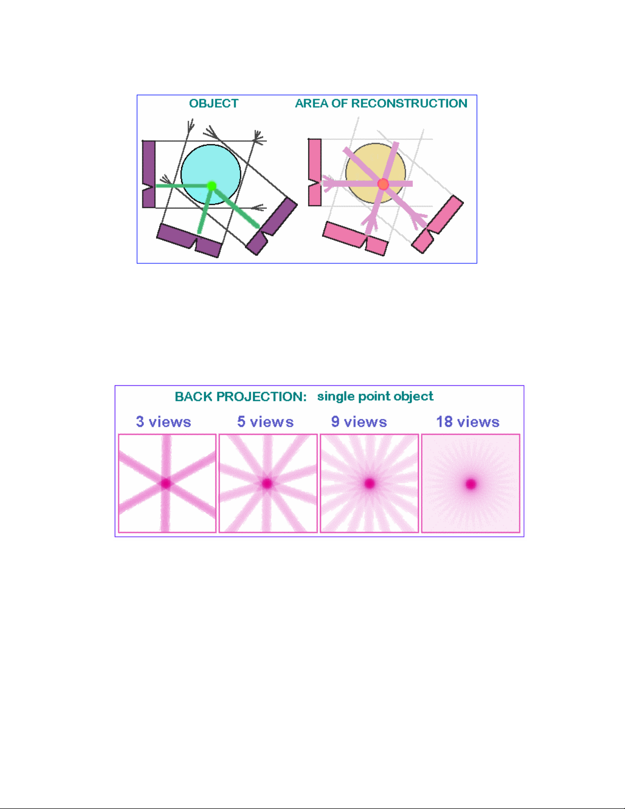
1.2 Basis principles of microtomogaphy
Any x-ray shadow image is corresponding to a two-dimensional projection from
the three-dimensional object. In the simplest case, we can describe it as a
parallel x-ray illumination. In this approximation, each point on the shadow
image contains the integration of absorption information inside the three-
dimensional object in the corresponding partial x-ray beam.
For parallel geometry one can divide the problem of a three-dimensional
reconstruction from two-dimensional projections into the serial reconstruction of
two-dimensional object slices from one-dimensional shadow lines. Let's show a
possibility of this reconstruction on a simple example, an object with only one
point with significant absorption in an unknown place. In the one-dimensional
shadow line we will have a decreasing of intensity of the shadow of absorption
in the object area, see figure on the next page. Now we can initialise in the
computer memory an empty array of pixels (picture elements) corresponding to
possible object displacement. Of course, one must be sure that all parts of the
reconstructed object will be inside the field of view. Because we have the
position of the shadow from the absorption points of the object, we can mark on
the area of reconstruction in the computer memory all possible positions of
absorption points inside the object as lines.
SkyScan 1076 In vivo Microtomograph
_
_
__
_
__
_
__
_
__
_
__
_
__
_
__
_
__
_
__
_
__
_
__
_
__
_
__
_
__
_
__
_
__
_
__
_
__
_
__
_
__
_
__
_
__
_
__
_
__
_
__
_
__
_
__
_
__
_
__
_
__
_
__
_
__
_
__
_
__
_
__
_
__
_
__
_
__
_
__
_
__
_
__
_
__
_
__
_
__
_
__
_
__
_
__
_
__
_
__
_
__
_
__
_
__
_
__
_
__
_
__
_
__
_
__
_
__
_
__
_
__
_
__
_
__
_
__
_
__
_
__
_
__
_
__
_
__
_
__
_
__
_
__
_
__
_
__
_
_
-
-
--
-
--
-
--
-
--
-
--
-
--
-
--
-
--
-
--
-
--
-
--
-
--
-
--
-
--
-
--
-
--
-
--
-
--
-
--
-
--
-
--
-
--
-
--
-
--
-
--
-
--
-
--
-
--
-
--
-
--
-
--
-
--
-
--
-
--
-
--
-
--
-
--
-
--
-
--
-
--
-
--
-
--
-
--
-
--
-
--
-
--
-
--
-
--
-
--
-
--
-
--
-
--
-
--
-
--
-
--
-
--
-
--
-
--
-
--
-
--
-
--
-
--
-
--
-
--
-
--
-
--
-
--
-
--
-
--
-
--
-
--
-
--
-
--
-
--
-
--
-
--
-
--
-
--
-
--
-
--
-
--
-
--
-
--
-
--
-
--
-
--
-
--
-
--
-
--
-
--
-
--
-
--
-
--
-
--
-
--
-
--
-
--
-
--
-
--
-
--
-
--
-
--
-
--
-
--
-
--
-
--
-
--
-
--
-
--
-
--
-
--
-
--
-
--
-
--
-
--
-
--
-
--
-
--
-
--
-
--
-
--
-
--
-
--
-
-
Instruction Manual 6
Now let's rotate our object and repeat this operation. In each new rotation
position of the object, we will add to the area of reconstruction the lines of
possible object positions corresponding to position of shadow. This operation is
named "back-projection". After several rotations we can localise the position of
the absorption point inside the area of reconstruction. In increasing the number
of shadow projections from different views this localisation become more and
more defined.
In the case of reconstruction from an infinite number of projections one can get
an image with a good definition of the absorption area position inside the initial
object. At the same time a blur area will accompany the pointer image because
it is produced as a superposition of lines with all inclinations. Now we know
what image will be produced from the pointer object and we can "pre-correct"
the initial information in absorption lines to make the resulting image more
corresponding to the real object. This correction ad some "negative absorption"
outside the point of the object shadows to eliminate the positive blur in the back
projection process (convolution).

SkyScan 1076 In vivo Microtomograph
_
_
__
_
__
_
__
_
__
_
__
_
__
_
__
_
__
_
__
_
__
_
__
_
__
_
__
_
__
_
__
_
__
_
__
_
__
_
__
_
__
_
__
_
__
_
__
_
__
_
__
_
__
_
__
_
__
_
__
_
__
_
__
_
__
_
__
_
__
_
__
_
__
_
__
_
__
_
__
_
__
_
__
_
__
_
__
_
__
_
__
_
__
_
__
_
__
_
__
_
__
_
__
_
__
_
__
_
__
_
__
_
__
_
__
_
__
_
__
_
__
_
__
_
__
_
__
_
__
_
__
_
__
_
__
_
__
_
__
_
__
_
__
_
__
_
__
_
_
-
-
--
-
--
-
--
-
--
-
--
-
--
-
--
-
--
-
--
-
--
-
--
-
--
-
--
-
--
-
--
-
--
-
--
-
--
-
--
-
--
-
--
-
--
-
--
-
--
-
--
-
--
-
--
-
--
-
--
-
--
-
--
-
--
-
--
-
--
-
--
-
--
-
--
-
--
-
--
-
--
-
--
-
--
-
--
-
--
-
--
-
--
-
--
-
--
-
--
-
--
-
--
-
--
-
--
-
--
-
--
-
--
-
--
-
--
-
--
-
--
-
--
-
--
-
--
-
--
-
--
-
--
-
--
-
--
-
--
-
--
-
--
-
--
-
--
-
--
-
--
-
--
-
--
-
--
-
--
-
--
-
--
-
--
-
--
-
--
-
--
-
--
-
--
-
--
-
--
-
--
-
--
-
--
-
--
-
--
-
--
-
--
-
--
-
--
-
--
-
--
-
--
-
--
-
--
-
--
-
--
-
--
-
--
-
--
-
--
-
--
-
--
-
--
-
--
-
--
-
--
-
--
-
--
-
--
-
--
-
--
-
--
-
--
-
--
-
-
Instruction Manual 7
The same algorithm can produce the cross-section image not only from the
single point object. Any real object can be represented as a big number of
separate absorption voxels and linear absorption in any x-ray beam is
corresponding to the sum of all absorption from all voxels inside this beam. By
this way the two-dimensional cross-sections of the object can be reconstructed
from the one-dimensional shadow lines in different views.
Unfortunately practically all x-ray sources cannot generate parallel beams. In a
real case, one will use a pointer source and fan x-ray beam in the object area.
For tomography reconstruction we can find the solution of this problem by the
reordering of the shadow information. New pseudo-parallel beams can be
constructed from the parts of several fan beams with different views and the
same reconstruction method for fan-beam x-ray sources can be used.

SkyScan 1076 In vivo Microtomograph
_
_
__
_
__
_
__
_
__
_
__
_
__
_
__
_
__
_
__
_
__
_
__
_
__
_
__
_
__
_
__
_
__
_
__
_
__
_
__
_
__
_
__
_
__
_
__
_
__
_
__
_
__
_
__
_
__
_
__
_
__
_
__
_
__
_
__
_
__
_
__
_
__
_
__
_
__
_
__
_
__
_
__
_
__
_
__
_
__
_
__
_
__
_
__
_
__
_
__
_
__
_
__
_
__
_
__
_
__
_
__
_
__
_
__
_
__
_
__
_
__
_
__
_
__
_
__
_
__
_
__
_
__
_
__
_
__
_
__
_
__
_
__
_
__
_
__
_
_
-
-
--
-
--
-
--
-
--
-
--
-
--
-
--
-
--
-
--
-
--
-
--
-
--
-
--
-
--
-
--
-
--
-
--
-
--
-
--
-
--
-
--
-
--
-
--
-
--
-
--
-
--
-
--
-
--
-
--
-
--
-
--
-
--
-
--
-
--
-
--
-
--
-
--
-
--
-
--
-
--
-
--
-
--
-
--
-
--
-
--
-
--
-
--
-
--
-
--
-
--
-
--
-
--
-
--
-
--
-
--
-
--
-
--
-
--
-
--
-
--
-
--
-
--
-
--
-
--
-
--
-
--
-
--
-
--
-
--
-
--
-
--
-
--
-
--
-
--
-
--
-
--
-
--
-
--
-
--
-
--
-
--
-
--
-
--
-
--
-
--
-
--
-
--
-
--
-
--
-
--
-
--
-
--
-
--
-
--
-
--
-
--
-
--
-
--
-
--
-
--
-
--
-
--
-
--
-
--
-
--
-
--
-
--
-
--
-
--
-
--
-
--
-
--
-
--
-
--
-
--
-
--
-
--
-
--
-
--
-
--
-
--
-
--
-
--
-
-
Instruction Manual 8
In the case of x-ray acquisition, the image contains information about the
intensity reduction inside the three-dimensional object. Because the x-ray
absorption is corresponding to exponential law, we can restore the linear
absorption information from the shadow image by logarithmisation.
This operation is very non-linear and any noise in the small signal areas can
produce significant errors in reconstruction. To eliminate these errors an
averaging of initial data and results of logarithmisation can be used. On the
another hand we can try to improve the signal to noise ratio in the shadow
image to reach the most representative information.
One more effective way of noise reduction in the reconstruction process is a
special selection of correction function for convolution before back projection. In
the simplest case (described above) the correction function produces two
"negative absorption" reactions around any signal or noise peak in the shadow
line and this behaviour becomes very dangerous for noisy initial information.
Special selection of convolution function for correction with spectral limitation by
“Hamming window” allows solving this problem. In x-ray microtomography an
information from voxel with very small physical size should be detected and
right choice of parameters for noise reduction becomes very important.

SkyScan 1076 In vivo Microtomograph
_
_
__
_
__
_
__
_
__
_
__
_
__
_
__
_
__
_
__
_
__
_
__
_
__
_
__
_
__
_
__
_
__
_
__
_
__
_
__
_
__
_
__
_
__
_
__
_
__
_
__
_
__
_
__
_
__
_
__
_
__
_
__
_
__
_
__
_
__
_
__
_
__
_
__
_
__
_
__
_
__
_
__
_
__
_
__
_
__
_
__
_
__
_
__
_
__
_
__
_
__
_
__
_
__
_
__
_
__
_
__
_
__
_
__
_
__
_
__
_
__
_
__
_
__
_
__
_
__
_
__
_
__
_
__
_
__
_
__
_
__
_
__
_
__
_
__
_
_
-
-
--
-
--
-
--
-
--
-
--
-
--
-
--
-
--
-
--
-
--
-
--
-
--
-
--
-
--
-
--
-
--
-
--
-
--
-
--
-
--
-
--
-
--
-
--
-
--
-
--
-
--
-
--
-
--
-
--
-
--
-
--
-
--
-
--
-
--
-
--
-
--
-
--
-
--
-
--
-
--
-
--
-
--
-
--
-
--
-
--
-
--
-
--
-
--
-
--
-
--
-
--
-
--
-
--
-
--
-
--
-
--
-
--
-
--
-
--
-
--
-
--
-
--
-
--
-
--
-
--
-
--
-
--
-
--
-
--
-
--
-
--
-
--
-
--
-
--
-
--
-
--
-
--
-
--
-
--
-
--
-
--
-
--
-
--
-
--
-
--
-
--
-
--
-
--
-
--
-
--
-
--
-
--
-
--
-
--
-
--
-
--
-
--
-
--
-
--
-
--
-
--
-
--
-
--
-
--
-
--
-
--
-
--
-
--
-
--
-
--
-
--
-
--
-
--
-
--
-
--
-
--
-
--
-
--
-
--
-
--
-
--
-
--
-
--
-
-
Instruction Manual 9
1.3 Reconstruction to image
1.3.1 Acquisition, creation of acquisition data
During the acquisition the source-detector pair will rotate over 180 degrees. At
each position the shadow image or transmission image will be acquired.
Cone beam acquisitions saves all of these projection images as 16 bit TIF files.
The data set after scanning consists of a set of images, all of them are normal
transmission X-ray images. For each position over the 180 degrees rotation a
full 16 bit shadow image will be stored on disk. The number of files after this
acquisition is thus depending upon the rotation step selected. For a typical step
of 0.7 degree, there will be 257 images plus a small number to start the re-
sampling of the images for horizontal or fan compensation of the x-ray beam.
1.3.2 Start of the reconstruction
After the acquisition is finished we have to start the reconstruction. We will use
the 16-bit TIF shadow images for the reconstruction. We will now generate from
this, by using the reconstruction algorithm, a raw data reconstructed cross-
section. This is not yet an image, it is a float point matrix holding absorption
values in the reconstructed cross-section.
The size of the matrix is like the
number of pixels inside a cross-
section or in a line on the CCD
array (n is the number of pixels
in a line of the shadow image or
the CCD array).
We can save the reconstructed
cross-section as a float point
matrix holding the attenuation
values after the reconstruction
or as explained in the next
section transform it to an image
with the 256 grey values (8bit).

SkyScan 1076 In vivo Microtomograph
_
_
__
_
__
_
__
_
__
_
__
_
__
_
__
_
__
_
__
_
__
_
__
_
__
_
__
_
__
_
__
_
__
_
__
_
__
_
__
_
__
_
__
_
__
_
__
_
__
_
__
_
__
_
__
_
__
_
__
_
__
_
__
_
__
_
__
_
__
_
__
_
__
_
__
_
__
_
__
_
__
_
__
_
__
_
__
_
__
_
__
_
__
_
__
_
__
_
__
_
__
_
__
_
__
_
__
_
__
_
__
_
__
_
__
_
__
_
__
_
__
_
__
_
__
_
__
_
__
_
__
_
__
_
__
_
__
_
__
_
__
_
__
_
__
_
__
_
_
-
-
--
-
--
-
--
-
--
-
--
-
--
-
--
-
--
-
--
-
--
-
--
-
--
-
--
-
--
-
--
-
--
-
--
-
--
-
--
-
--
-
--
-
--
-
--
-
--
-
--
-
--
-
--
-
--
-
--
-
--
-
--
-
--
-
--
-
--
-
--
-
--
-
--
-
--
-
--
-
--
-
--
-
--
-
--
-
--
-
--
-
--
-
--
-
--
-
--
-
--
-
--
-
--
-
--
-
--
-
--
-
--
-
--
-
--
-
--
-
--
-
--
-
--
-
--
-
--
-
--
-
--
-
--
-
--
-
--
-
--
-
--
-
--
-
--
-
--
-
--
-
--
-
--
-
--
-
--
-
--
-
--
-
--
-
--
-
--
-
--
-
--
-
--
-
--
-
--
-
--
-
--
-
--
-
--
-
--
-
--
-
--
-
--
-
--
-
--
-
--
-
--
-
--
-
--
-
--
-
--
-
--
-
--
-
--
-
--
-
--
-
--
-
--
-
--
-
--
-
--
-
--
-
--
-
--
-
--
-
--
-
--
-
--
-
--
-
-
Instruction Manual 10
1.3.3 Cross-section to image
After creating the raw data reconstructed cross-section, we have to generate an
image. Any images uses 256 gray scales. Therefore, we have to find away to
convert the 12 bits or more, depending upon the camera, information into a
gray scale image.
Minimum and maximum values are selected. All values between these will be
displayed as half tone. In a normal image, all attenuation values below the
minimum will be white everything above the maximum will be displayed as
black. Reconstructed array will be shown as a half-tone image of cross- section
with linear conversion to 256-grades of gray inside selected density interval.
In the Skyscan systems, using a Windows environment, the final image
generated can be exported to BMP, RAW 16Bit or TXT -files.
Following image summarizes all action and steps to generate the cross
sectional data.

SkyScan 1076 In vivo Microtomograph
_
_
__
_
__
_
__
_
__
_
__
_
__
_
__
_
__
_
__
_
__
_
__
_
__
_
__
_
__
_
__
_
__
_
__
_
__
_
__
_
__
_
__
_
__
_
__
_
__
_
__
_
__
_
__
_
__
_
__
_
__
_
__
_
__
_
__
_
__
_
__
_
__
_
__
_
__
_
__
_
__
_
__
_
__
_
__
_
__
_
__
_
__
_
__
_
__
_
__
_
__
_
__
_
__
_
__
_
__
_
__
_
__
_
__
_
__
_
__
_
__
_
__
_
__
_
__
_
__
_
__
_
__
_
__
_
__
_
__
_
__
_
__
_
__
_
__
_
_
-
-
--
-
--
-
--
-
--
-
--
-
--
-
--
-
--
-
--
-
--
-
--
-
--
-
--
-
--
-
--
-
--
-
--
-
--
-
--
-
--
-
--
-
--
-
--
-
--
-
--
-
--
-
--
-
--
-
--
-
--
-
--
-
--
-
--
-
--
-
--
-
--
-
--
-
--
-
--
-
--
-
--
-
--
-
--
-
--
-
--
-
--
-
--
-
--
-
--
-
--
-
--
-
--
-
--
-
--
-
--
-
--
-
--
-
--
-
--
-
--
-
--
-
--
-
--
-
--
-
--
-
--
-
--
-
--
-
--
-
--
-
--
-
--
-
--
-
--
-
--
-
--
-
--
-
--
-
--
-
--
-
--
-
--
-
--
-
--
-
--
-
--
-
--
-
--
-
--
-
--
-
--
-
--
-
--
-
--
-
--
-
--
-
--
-
--
-
--
-
--
-
--
-
--
-
--
-
--
-
--
-
--
-
--
-
--
-
--
-
--
-
--
-
--
-
--
-
--
-
--
-
--
-
--
-
--
-
--
-
--
-
--
-
--
-
--
-
-
Instruction Manual 11
2 SKYSCAN 1076 SYSTEM OVERVIEW
SPECIFICATIONS:
Maximum object size 68mm(D) x 200mm(L) for rats or 3
5mm(D) x 200mm(L)
for mice, 17mm(L) per single scan
X-ray source 20-100kV, 10W, <5um spot size (@4W), >10000h
estimated lifetime, air cooled sealed type, 4-positions
automatic filter changer for energy selection
X-ray detector 10 Megapixel (4000x2300x12bit) cooled digital
X-
Ray camera with fibre-optic coupling to scintillator
Spatial resolution User selectable pixel size 9µm / 18µm / 35µm
(isotropic), 15µm low-contrast resolution (10% MTF)
Projection / cross-section
Image size and formats
1000x520…8000x2000 pixels projection images (16-
bit TIFF format)
1000x1000…8000x8000 pixels cross-section (BMP,
RAW 16-bit, TXT formats, converter to JPEG)
X-ray loading to the animal 0.1-0.5 Gy per scan typical
Scanning system
source-detector pair rotation with 0.02 deg. min. step
size, 50um object positioning accuracy with 400mm
travel, 50mm camera positioning/alignment with 1um
accuracy, <10 microns overall stability during scanning
Software package
scanner control, preview (35x200mm scan),
acquisition for reconstruction, volumetric (cone-beam)
reconstruction of one / several / all cross sections,
ROI-reconstruction, local density measurements in
HU, 3D-rendering, virtual manipulation with
reconstructed object, morphological analysis in 2D and
3D
Reconstruction algorithm
Modified Feldkamp: multislice volumetric (cone-beam)
reconstruction. Up to 2000 slices can be reconstructed
after one scan. Full image mode, partial reconstruction
mode, possibility for detail local reconstruction with
object bigger than field of view.
Radiation safety <1uSv/h average during full scan at 10cm from the
instrument surface
Installation requirements
Power 100-130V/5A/50-60Hz or
200-240V/3A/50-60Hz, 18-28C temperature,
<85% humidity, no condensation,
vibrations 0.1…100Hz <40 microns
Size/Weight Desk top instrument 750mm(H) x 650mm(D) x
2200mm(W), 150Kg + computer, monitor, keyboard,
mouse

SkyScan 1076 In vivo Microtomograph
_
_
__
_
__
_
__
_
__
_
__
_
__
_
__
_
__
_
__
_
__
_
__
_
__
_
__
_
__
_
__
_
__
_
__
_
__
_
__
_
__
_
__
_
__
_
__
_
__
_
__
_
__
_
__
_
__
_
__
_
__
_
__
_
__
_
__
_
__
_
__
_
__
_
__
_
__
_
__
_
__
_
__
_
__
_
__
_
__
_
__
_
__
_
__
_
__
_
__
_
__
_
__
_
__
_
__
_
__
_
__
_
__
_
__
_
__
_
__
_
__
_
__
_
__
_
__
_
__
_
__
_
__
_
__
_
__
_
__
_
__
_
__
_
__
_
__
_
_
-
-
--
-
--
-
--
-
--
-
--
-
--
-
--
-
--
-
--
-
--
-
--
-
--
-
--
-
--
-
--
-
--
-
--
-
--
-
--
-
--
-
--
-
--
-
--
-
--
-
--
-
--
-
--
-
--
-
--
-
--
-
--
-
--
-
--
-
--
-
--
-
--
-
--
-
--
-
--
-
--
-
--
-
--
-
--
-
--
-
--
-
--
-
--
-
--
-
--
-
--
-
--
-
--
-
--
-
--
-
--
-
--
-
--
-
--
-
--
-
--
-
--
-
--
-
--
-
--
-
--
-
--
-
--
-
--
-
--
-
--
-
--
-
--
-
--
-
--
-
--
-
--
-
--
-
--
-
--
-
--
-
--
-
--
-
--
-
--
-
--
-
--
-
--
-
--
-
--
-
--
-
--
-
--
-
--
-
--
-
--
-
--
-
--
-
--
-
--
-
--
-
--
-
--
-
--
-
--
-
--
-
--
-
--
-
--
-
--
-
--
-
--
-
--
-
--
-
--
-
--
-
--
-
--
-
--
-
--
-
--
-
--
-
--
-
--
-
-
Instruction Manual 12
The "SkyScan-1076" is a high- resolution low-dose X-ray scanner for in-vivo
3D-reconstruction with spatial resolution of up to 15 microns inside the small
laboratory animals (rats, mice, etc.). It consists of the combination of Micro-CT
system and a computer with system control software and reconstruction
software. This system allows reconstructing non-invasively any cross-section
through the animal body with possibilities to convert the reconstructed dataset
into a realistic 3D-image and calculate internal morphological parameters.
The equipment contains an X-ray microfocus tube with high-voltage power
supply, a rotation stage with overall accuracy of <10µm, a translation stage, a
two-dimensional X-ray CCD-camera connected to the frame-grabber and a
Dual Intel Xeon computer with LCD monitor.
All subsystems of the X-Ray Microtomograph are inside a steel desktop case.

SkyScan 1076 In vivo Microtomograph
_
_
__
_
__
_
__
_
__
_
__
_
__
_
__
_
__
_
__
_
__
_
__
_
__
_
__
_
__
_
__
_
__
_
__
_
__
_
__
_
__
_
__
_
__
_
__
_
__
_
__
_
__
_
__
_
__
_
__
_
__
_
__
_
__
_
__
_
__
_
__
_
__
_
__
_
__
_
__
_
__
_
__
_
__
_
__
_
__
_
__
_
__
_
__
_
__
_
__
_
__
_
__
_
__
_
__
_
__
_
__
_
__
_
__
_
__
_
__
_
__
_
__
_
__
_
__
_
__
_
__
_
__
_
__
_
__
_
__
_
__
_
__
_
__
_
__
_
_
-
-
--
-
--
-
--
-
--
-
--
-
--
-
--
-
--
-
--
-
--
-
--
-
--
-
--
-
--
-
--
-
--
-
--
-
--
-
--
-
--
-
--
-
--
-
--
-
--
-
--
-
--
-
--
-
--
-
--
-
--
-
--
-
--
-
--
-
--
-
--
-
--
-
--
-
--
-
--
-
--
-
--
-
--
-
--
-
--
-
--
-
--
-
--
-
--
-
--
-
--
-
--
-
--
-
--
-
--
-
--
-
--
-
--
-
--
-
--
-
--
-
--
-
--
-
--
-
--
-
--
-
--
-
--
-
--
-
--
-
--
-
--
-
--
-
--
-
--
-
--
-
--
-
--
-
--
-
--
-
--
-
--
-
--
-
--
-
--
-
--
-
--
-
--
-
--
-
--
-
--
-
--
-
--
-
--
-
--
-
--
-
--
-
--
-
--
-
--
-
--
-
--
-
--
-
--
-
--
-
--
-
--
-
--
-
--
-
--
-
--
-
--
-
--
-
--
-
--
-
--
-
--
-
--
-
--
-
--
-
--
-
--
-
--
-
--
-
-
Instruction Manual 13
For "SkyScan-1076” the X-ray microfocus tube with 5 micron focal spot size
operates at 20-100kV / 0-250µA. The special X-ray CCD-camera is based on
10 Megapixel (4000x2300 pixels) cooled CCD-sensor with fibre optic coupling
to x-ray scintillator
The X-ray shadow projections are digitised as 1000x520 to 8000x2000 pixels
with 4096 brightness gradations (12 bit). The reconstructed cross-sections have
a 1000x1000 to 8000x8000 pixels (float point) format and 9 /18 /35µm pixel
size in any place of the scanning area. The scanning area is 68mm x200mm or
35mm x 200mm (two carbon-composite beds supplied)
For the reconstruction one can use a volumetric (cone-beam) reconstruction of
one / several / all cross-sections or a ROI-reconstruction. After the serial
reconstruction, one can display the cross-sections onto the screen as well as
construct a realistic 3D-image with possibilities to "rotate" and "cut" the object
model. On this model, one can calculate the internal morphological parameters.
SkyScan 1076 In vivo Microtomograph
_
_
__
_
__
_
__
_
__
_
__
_
__
_
__
_
__
_
__
_
__
_
__
_
__
_
__
_
__
_
__
_
__
_
__
_
__
_
__
_
__
_
__
_
__
_
__
_
__
_
__
_
__
_
__
_
__
_
__
_
__
_
__
_
__
_
__
_
__
_
__
_
__
_
__
_
__
_
__
_
__
_
__
_
__
_
__
_
__
_
__
_
__
_
__
_
__
_
__
_
__
_
__
_
__
_
__
_
__
_
__
_
__
_
__
_
__
_
__
_
__
_
__
_
__
_
__
_
__
_
__
_
__
_
__
_
__
_
__
_
__
_
__
_
__
_
__
_
_
-
-
--
-
--
-
--
-
--
-
--
-
--
-
--
-
--
-
--
-
--
-
--
-
--
-
--
-
--
-
--
-
--
-
--
-
--
-
--
-
--
-
--
-
--
-
--
-
--
-
--
-
--
-
--
-
--
-
--
-
--
-
--
-
--
-
--
-
--
-
--
-
--
-
--
-
--
-
--
-
--
-
--
-
--
-
--
-
--
-
--
-
--
-
--
-
--
-
--
-
--
-
--
-
--
-
--
-
--
-
--
-
--
-
--
-
--
-
--
-
--
-
--
-
--
-
--
-
--
-
--
-
--
-
--
-
--
-
--
-
--
-
--
-
--
-
--
-
--
-
--
-
--
-
--
-
--
-
--
-
--
-
--
-
--
-
--
-
--
-
--
-
--
-
--
-
--
-
--
-
--
-
--
-
--
-
--
-
--
-
--
-
--
-
--
-
--
-
--
-
--
-
--
-
--
-
--
-
--
-
--
-
--
-
--
-
--
-
--
-
--
-
--
-
--
-
--
-
--
-
--
-
--
-
--
-
--
-
--
-
--
-
--
-
--
-
--
-
-
Instruction Manual 14
3 INSTALLATION PROCEDURE
In case of damage during transportation or any defect in scanner operation,
please contact your local Skyscan distributor (see www.skyscan.be for
distributors). Alternatively, send the scanner directly to Skyscan, after
contacting first, at following mail address:
Skyscan, Vluchtenburgstraat 3, Aartselaar B-2630, BELGIUM.
Email: info@skyscan.be, Tel: +32 3 877 57 05, Fax: +32 3 877 57 69
Only trained people by Skyscan are authorized to do service and
reparations on the scanner!
For lifting and carrying, remove the four black plastic caps and put the supplied
steel bars through the holes. One can carry the system with four persons.
Use the steel bars as handgrips.
The table, on which the system will be put, should be strong enough to support
a weight of 150 – 200 kg. The distance between the backside of the system
and the wall should be at least 10 cm, necessary for the airflow.
SkyScan 1076 In vivo Microtomograph
_
_
__
_
__
_
__
_
__
_
__
_
__
_
__
_
__
_
__
_
__
_
__
_
__
_
__
_
__
_
__
_
__
_
__
_
__
_
__
_
__
_
__
_
__
_
__
_
__
_
__
_
__
_
__
_
__
_
__
_
__
_
__
_
__
_
__
_
__
_
__
_
__
_
__
_
__
_
__
_
__
_
__
_
__
_
__
_
__
_
__
_
__
_
__
_
__
_
__
_
__
_
__
_
__
_
__
_
__
_
__
_
__
_
__
_
__
_
__
_
__
_
__
_
__
_
__
_
__
_
__
_
__
_
__
_
__
_
__
_
__
_
__
_
__
_
__
_
_
-
-
--
-
--
-
--
-
--
-
--
-
--
-
--
-
--
-
--
-
--
-
--
-
--
-
--
-
--
-
--
-
--
-
--
-
--
-
--
-
--
-
--
-
--
-
--
-
--
-
--
-
--
-
--
-
--
-
--
-
--
-
--
-
--
-
--
-
--
-
--
-
--
-
--
-
--
-
--
-
--
-
--
-
--
-
--
-
--
-
--
-
--
-
--
-
--
-
--
-
--
-
--
-
--
-
--
-
--
-
--
-
--
-
--
-
--
-
--
-
--
-
--
-
--
-
--
-
--
-
--
-
--
-
--
-
--
-
--
-
--
-
--
-
--
-
--
-
--
-
--
-
--
-
--
-
--
-
--
-
--
-
--
-
--
-
--
-
--
-
--
-
--
-
--
-
--
-
--
-
--
-
--
-
--
-
--
-
--
-
--
-
--
-
--
-
--
-
--
-
--
-
--
-
--
-
--
-
--
-
--
-
--
-
--
-
--
-
--
-
--
-
--
-
--
-
--
-
--
-
--
-
--
-
--
-
--
-
--
-
--
-
--
-
--
-
--
-
-
Instruction Manual 15
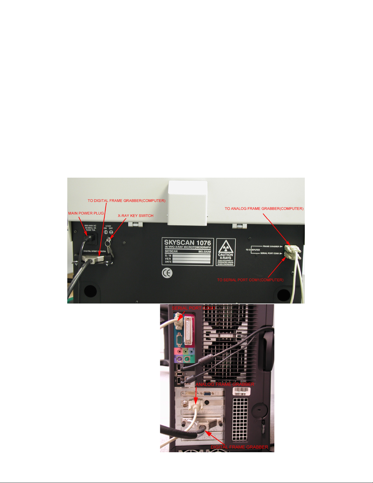
3.1 Connections
To start the system one should make the connections shown in the figure
below. All interconnections should be made before connection of the main
power plug to 220-240 V AC or 100-130V AC.
Connect the scanner to the computer:
•Use a serial cable from the lowest serial connector on the system to the
serial Port COM1 on the computer.
•Use second serial cable from the upper serial connector on the system
to the analog frame grabber on the computer.
•Use video cable from digital x-ray camera connector on the system to
the digital frame grabber on the computer.
The length of every signal cables is 2m. Use only the supplied signal cables.
The digital and analog frame-grabbers are pre-installed on the computer.
Interconnections for SkyScan1076:
Connections for computer:

SkyScan 1076 In vivo Microtomograph
_
_
__
_
__
_
__
_
__
_
__
_
__
_
__
_
__
_
__
_
__
_
__
_
__
_
__
_
__
_
__
_
__
_
__
_
__
_
__
_
__
_
__
_
__
_
__
_
__
_
__
_
__
_
__
_
__
_
__
_
__
_
__
_
__
_
__
_
__
_
__
_
__
_
__
_
__
_
__
_
__
_
__
_
__
_
__
_
__
_
__
_
__
_
__
_
__
_
__
_
__
_
__
_
__
_
__
_
__
_
__
_
__
_
__
_
__
_
__
_
__
_
__
_
__
_
__
_
__
_
__
_
__
_
__
_
__
_
__
_
__
_
__
_
__
_
__
_
_
-
-
--
-
--
-
--
-
--
-
--
-
--
-
--
-
--
-
--
-
--
-
--
-
--
-
--
-
--
-
--
-
--
-
--
-
--
-
--
-
--
-
--
-
--
-
--
-
--
-
--
-
--
-
--
-
--
-
--
-
--
-
--
-
--
-
--
-
--
-
--
-
--
-
--
-
--
-
--
-
--
-
--
-
--
-
--
-
--
-
--
-
--
-
--
-
--
-
--
-
--
-
--
-
--
-
--
-
--
-
--
-
--
-
--
-
--
-
--
-
--
-
--
-
--
-
--
-
--
-
--
-
--
-
--
-
--
-
--
-
--
-
--
-
--
-
--
-
--
-
--
-
--
-
--
-
--
-
--
-
--
-
--
-
--
-
--
-
--
-
--
-
--
-
--
-
--
-
--
-
--
-
--
-
--
-
--
-
--
-
--
-
--
-
--
-
--
-
--
-
--
-
--
-
--
-
--
-
--
-
--
-
--
-
--
-
--
-
--
-
--
-
--
-
--
-
--
-
--
-
--
-
--
-
--
-
--
-
--
-
--
-
--
-
--
-
--
-
-
Instruction Manual 16
3.2 Power supply
Never connect 200-240V to a system meant for 100-130V and vice versa. Look
to the label above the AC inlet (see picture on previous page).
The replaceable fuse is the same for both main voltages: type T rate 5A. Before
replacement of the fuse, disconnect the power cable from the system.
After connection of power cable to the system and wall socket one can start
system by power switch in the front panel.
3.3 Starting up Skyscan1076
Switch the system on by the Power Switch.
Start the external computer also. The start procedure for computer can take
couple of seconds with following start of “Windows 2000” or “Windows XP”.
X-ray scanner should be always ON before starting control software in the
external computer. Control and reconstruction software for Skyscan1076
system can be started from corresponding icon on the screen.
3.4 X-ray Key switch
A key switch for the x-ray source is located next to the AC inlet of the system.
(See picture on previous page.)
For normal operations of scanner the switch "X-RAY" must be turned ON. You
can keep the ON position of this switch continuously even when switching off
and on the main power.
For security reasons the X-ray tube can be disabled or switched off by using
the “X-RAY KEY SWITCH”.

SkyScan 1076 In vivo Microtomograph
_
_
__
_
__
_
__
_
__
_
__
_
__
_
__
_
__
_
__
_
__
_
__
_
__
_
__
_
__
_
__
_
__
_
__
_
__
_
__
_
__
_
__
_
__
_
__
_
__
_
__
_
__
_
__
_
__
_
__
_
__
_
__
_
__
_
__
_
__
_
__
_
__
_
__
_
__
_
__
_
__
_
__
_
__
_
__
_
__
_
__
_
__
_
__
_
__
_
__
_
__
_
__
_
__
_
__
_
__
_
__
_
__
_
__
_
__
_
__
_
__
_
__
_
__
_
__
_
__
_
__
_
__
_
__
_
__
_
__
_
__
_
__
_
__
_
__
_
_
-
-
--
-
--
-
--
-
--
-
--
-
--
-
--
-
--
-
--
-
--
-
--
-
--
-
--
-
--
-
--
-
--
-
--
-
--
-
--
-
--
-
--
-
--
-
--
-
--
-
--
-
--
-
--
-
--
-
--
-
--
-
--
-
--
-
--
-
--
-
--
-
--
-
--
-
--
-
--
-
--
-
--
-
--
-
--
-
--
-
--
-
--
-
--
-
--
-
--
-
--
-
--
-
--
-
--
-
--
-
--
-
--
-
--
-
--
-
--
-
--
-
--
-
--
-
--
-
--
-
--
-
--
-
--
-
--
-
--
-
--
-
--
-
--
-
--
-
--
-
--
-
--
-
--
-
--
-
--
-
--
-
--
-
--
-
--
-
--
-
--
-
--
-
--
-
--
-
--
-
--
-
--
-
--
-
--
-
--
-
--
-
--
-
--
-
--
-
--
-
--
-
--
-
--
-
--
-
--
-
--
-
--
-
--
-
--
-
--
-
--
-
--
-
--
-
--
-
--
-
--
-
--
-
--
-
--
-
--
-
--
-
--
-
--
-
--
-
-
Instruction Manual 17
3.5 X-Ray Shutter
Normally the X-Ray shutter is always in the closed position. The X-ray shutter is
open for acquiring one X-ray image or a scout scan and during scanning. The
LED’s indicate the X-Ray shutter position:
The X-ray shutter is open when
the red LED lights up.
The X-ray shutter is closed
when the green LED lights up.
SkyScan 1076 In vivo Microtomograph
_
_
__
_
__
_
__
_
__
_
__
_
__
_
__
_
__
_
__
_
__
_
__
_
__
_
__
_
__
_
__
_
__
_
__
_
__
_
__
_
__
_
__
_
__
_
__
_
__
_
__
_
__
_
__
_
__
_
__
_
__
_
__
_
__
_
__
_
__
_
__
_
__
_
__
_
__
_
__
_
__
_
__
_
__
_
__
_
__
_
__
_
__
_
__
_
__
_
__
_
__
_
__
_
__
_
__
_
__
_
__
_
__
_
__
_
__
_
__
_
__
_
__
_
__
_
__
_
__
_
__
_
__
_
__
_
__
_
__
_
__
_
__
_
__
_
__
_
_
-
-
--
-
--
-
--
-
--
-
--
-
--
-
--
-
--
-
--
-
--
-
--
-
--
-
--
-
--
-
--
-
--
-
--
-
--
-
--
-
--
-
--
-
--
-
--
-
--
-
--
-
--
-
--
-
--
-
--
-
--
-
--
-
--
-
--
-
--
-
--
-
--
-
--
-
--
-
--
-
--
-
--
-
--
-
--
-
--
-
--
-
--
-
--
-
--
-
--
-
--
-
--
-
--
-
--
-
--
-
--
-
--
-
--
-
--
-
--
-
--
-
--
-
--
-
--
-
--
-
--
-
--
-
--
-
--
-
--
-
--
-
--
-
--
-
--
-
--
-
--
-
--
-
--
-
--
-
--
-
--
-
--
-
--
-
--
-
--
-
--
-
--
-
--
-
--
-
--
-
--
-
--
-
--
-
--
-
--
-
--
-
--
-
--
-
--
-
--
-
--
-
--
-
--
-
--
-
--
-
--
-
--
-
--
-
--
-
--
-
--
-
--
-
--
-
--
-
--
-
--
-
--
-
--
-
--
-
--
-
--
-
--
-
--
-
--
-
-
Instruction Manual 18
4 SYSTEM CONTROL SOFTWARE
The software package for system control has the same operation principles as
any other Windows-based program. One can select any functions by "mouse"
from the menu / submenu in the top line and change modes and parameters by
"mouse pressing" to the corresponding control areas or buttons. To start the
Skyscan1076 control software double click on the corresponding icon:
After the program is started, an initialisation window is shown on the screen.
During initialisation, the object-bed moves to the outside position. After
initialisation, the shutter closes and the door become unlocked.
The start image on the screen contains the main menu bar and the control bar
in the top of the screen.
4.1 Tube setting and start.
In the control bar, one can find the button to switch the tube ON or OFF:
To start X-ray tube push X-ray button:
Voltage and current will be set automatically corresponding to current pixel size
and filter. Both values can be adjusted in “Options” -> “Scanning Modes” (see
5.3.4).
The Windows Taskbar in the bottom indicates the voltage and current settings
of the X-ray tube. The X-ray voltage and current are also shown on the front
panel display of the system.
In the case of first start or interrupt >8 hours after last usage of the x-ray
source, a new information dialog will appear into the screen. It will be indication
of aging (warming up) process for the soft start of the x-ray source. The aging
allows keeping a very long tube lifetime. Typical time of an aging process is 15-
17 minutes (for <1 month’s pause in tube usage). In the case of big differences
of voltage indications on the taskbar and in the front panel display of the system
(>20% from maximum values) contact your supplier for service.
After aging, tube will be switched off automatically. One can switch it on in any
time without extra delay. After tube start, the normal behaviour is an increasing
of the acceleration voltage in the screen indicators and in the front panel
display with following increasing of the current.
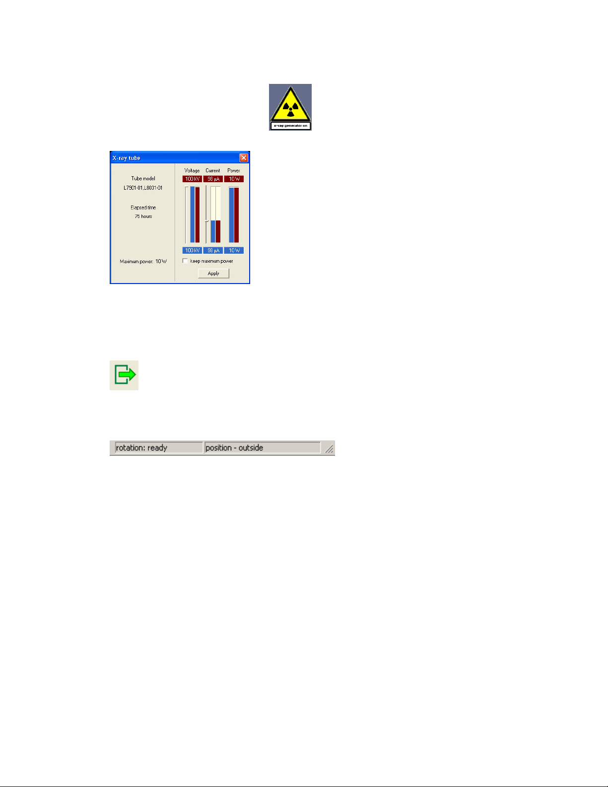
SkyScan 1076 In vivo Microtomograph
_
_
__
_
__
_
__
_
__
_
__
_
__
_
__
_
__
_
__
_
__
_
__
_
__
_
__
_
__
_
__
_
__
_
__
_
__
_
__
_
__
_
__
_
__
_
__
_
__
_
__
_
__
_
__
_
__
_
__
_
__
_
__
_
__
_
__
_
__
_
__
_
__
_
__
_
__
_
__
_
__
_
__
_
__
_
__
_
__
_
__
_
__
_
__
_
__
_
__
_
__
_
__
_
__
_
__
_
__
_
__
_
__
_
__
_
__
_
__
_
__
_
__
_
__
_
__
_
__
_
__
_
__
_
__
_
__
_
__
_
__
_
__
_
__
_
__
_
_
-
-
--
-
--
-
--
-
--
-
--
-
--
-
--
-
--
-
--
-
--
-
--
-
--
-
--
-
--
-
--
-
--
-
--
-
--
-
--
-
--
-
--
-
--
-
--
-
--
-
--
-
--
-
--
-
--
-
--
-
--
-
--
-
--
-
--
-
--
-
--
-
--
-
--
-
--
-
--
-
--
-
--
-
--
-
--
-
--
-
--
-
--
-
--
-
--
-
--
-
--
-
--
-
--
-
--
-
--
-
--
-
--
-
--
-
--
-
--
-
--
-
--
-
--
-
--
-
--
-
--
-
--
-
--
-
--
-
--
-
--
-
--
-
--
-
--
-
--
-
--
-
--
-
--
-
--
-
--
-
--
-
--
-
--
-
--
-
--
-
--
-
--
-
--
-
--
-
--
-
--
-
--
-
--
-
--
-
--
-
--
-
--
-
--
-
--
-
--
-
--
-
--
-
--
-
--
-
--
-
--
-
--
-
--
-
--
-
--
-
--
-
--
-
--
-
--
-
--
-
--
-
--
-
--
-
--
-
--
-
--
-
--
-
--
-
--
-
-
Instruction Manual 19
One can change the power settings of the tube by double clicking on the
“x-ray generator on” indicator:
Following dialog box will be shown onto the screen:
Left part of the dialog box shows information
about the type of x-ray source, elapsed time
(active emission) and maximum available power.
Right part is used for indication of current values
(red) and adjustment for new values (blue). New
values can be applied by pressing to Apply
button. The voltage reaches from 0 to 100 KV,
the current from 0 to 250 µA.
The “Keep maximum power” option adjusts
voltage from current or current from voltage to get maximum available power
from the x-ray source.
For animal/object replacement press “Remove object” button in the control bar:
Object will be moved out of scanner. The X-Ray tube will switch
off automatically and the door lock will become open.
The status bar in the bottom indicates the present position.
Now it’s possible to open the door by hand.
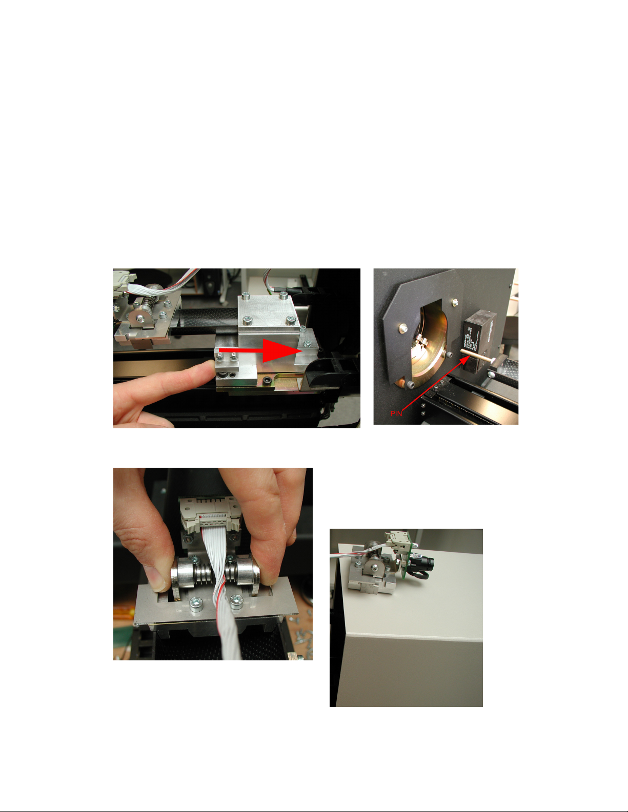
SkyScan 1076 In vivo Microtomograph
_
_
__
_
__
_
__
_
__
_
__
_
__
_
__
_
__
_
__
_
__
_
__
_
__
_
__
_
__
_
__
_
__
_
__
_
__
_
__
_
__
_
__
_
__
_
__
_
__
_
__
_
__
_
__
_
__
_
__
_
__
_
__
_
__
_
__
_
__
_
__
_
__
_
__
_
__
_
__
_
__
_
__
_
__
_
__
_
__
_
__
_
__
_
__
_
__
_
__
_
__
_
__
_
__
_
__
_
__
_
__
_
__
_
__
_
__
_
__
_
__
_
__
_
__
_
__
_
__
_
__
_
__
_
__
_
__
_
__
_
__
_
__
_
__
_
__
_
_
-
-
--
-
--
-
--
-
--
-
--
-
--
-
--
-
--
-
--
-
--
-
--
-
--
-
--
-
--
-
--
-
--
-
--
-
--
-
--
-
--
-
--
-
--
-
--
-
--
-
--
-
--
-
--
-
--
-
--
-
--
-
--
-
--
-
--
-
--
-
--
-
--
-
--
-
--
-
--
-
--
-
--
-
--
-
--
-
--
-
--
-
--
-
--
-
--
-
--
-
--
-
--
-
--
-
--
-
--
-
--
-
--
-
--
-
--
-
--
-
--
-
--
-
--
-
--
-
--
-
--
-
--
-
--
-
--
-
--
-
--
-
--
-
--
-
--
-
--
-
--
-
--
-
--
-
--
-
--
-
--
-
--
-
--
-
--
-
--
-
--
-
--
-
--
-
--
-
--
-
--
-
--
-
--
-
--
-
--
-
--
-
--
-
--
-
--
-
--
-
--
-
--
-
--
-
--
-
--
-
--
-
--
-
--
-
--
-
--
-
--
-
--
-
--
-
--
-
--
-
--
-
--
-
--
-
--
-
--
-
--
-
--
-
--
-
--
-
-
Instruction Manual 20
4.2 Animal holders
There are two standard carbon-composite object beds supplied with the
system.
The object bed with diameter 33 mm should be used for mice and the object
bed with diameter 65 mm should be used for rats. Both have the same length of
400 mm and a maximum scanning length of 200 mm.
One can exchange the two beds easily.
First, remove the already installed object bed.
Start system and control software, after initialisation the shutter closes (green
LED lights up). Open the door by hand. Close software and switch off the
system.
Move the bed by hand so that the “PIN” is completely outside the system.
Remove the visual camera by pressing on the two sides of the fastening
mechanism. Be careful that you don’t damage the flat cable.
Put the visual camera on top of the
door.
Table of contents


