Skywalker SWTC811 User manual
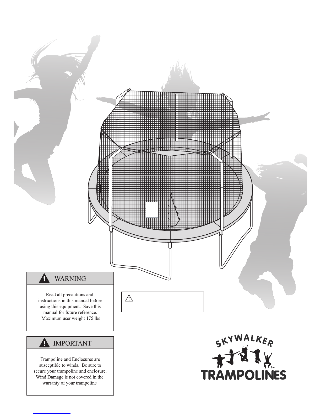
User’s Manual
Model
______________
SWTC811
CAUTION: Adult Assembly
Required
Model
...........................................3
.....................................4
..................................................4
.............................5
...............................6
...........................7
..............................9
..........10-11
Assembly..............................................................15-23
Care and Maintenance............ 24
Exploded Drawing and Parts List.........................13-14
Ordering Replacement Parts.................................14
Limited Warranty..................................................25
2
........................................8
.....
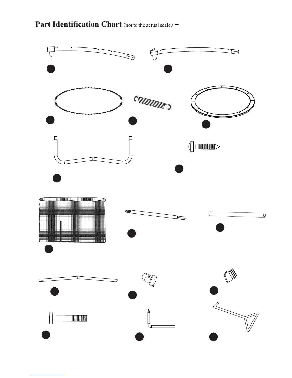
Part Identification Chart
SWTC811
..................................... 12
..............................

3
11.
12.
13.
14.
15.

4
14
round

5
6

7
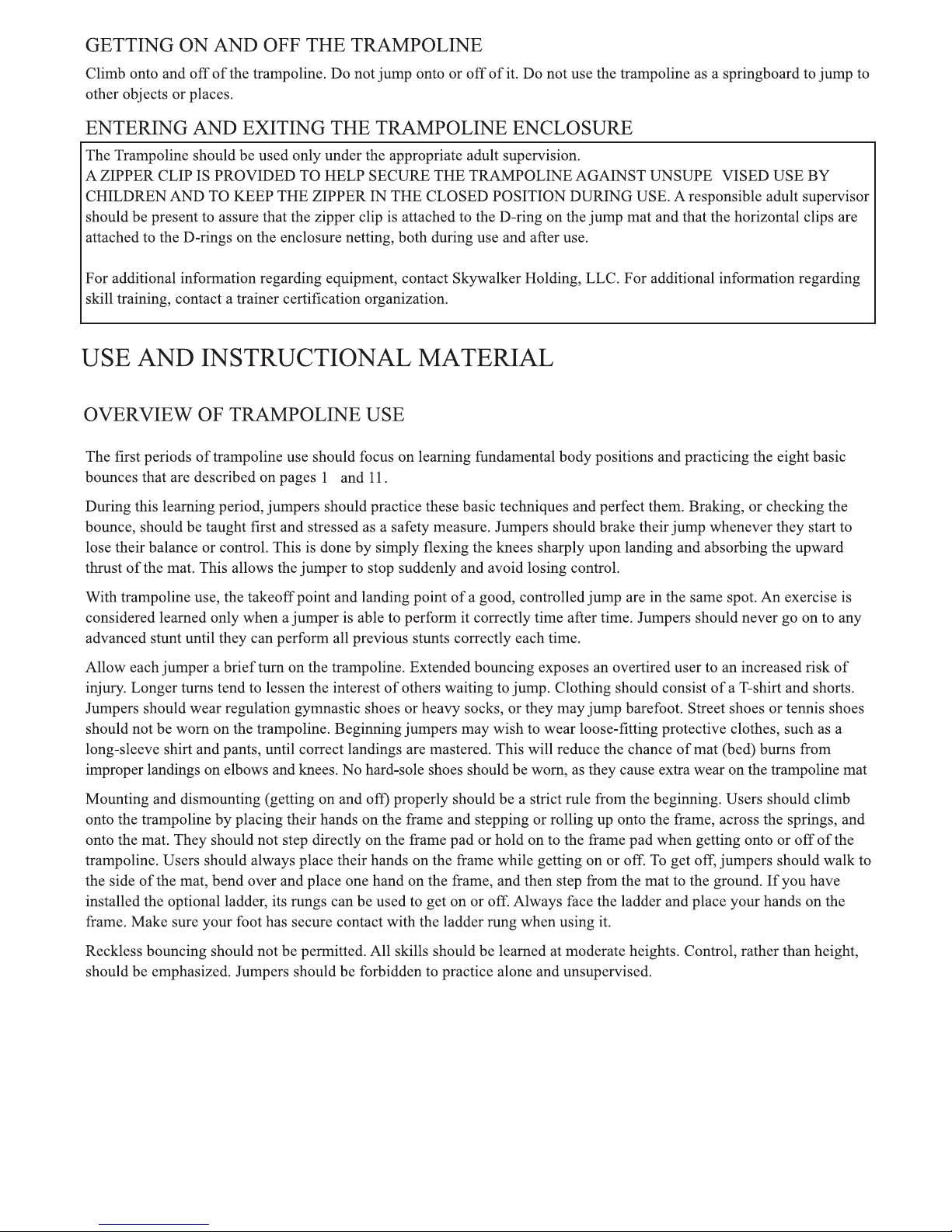
METHODS OF ACCIDENT PREVENTION
4
•
•
•
•
8
•
R
.
9
0
10
11
1
3
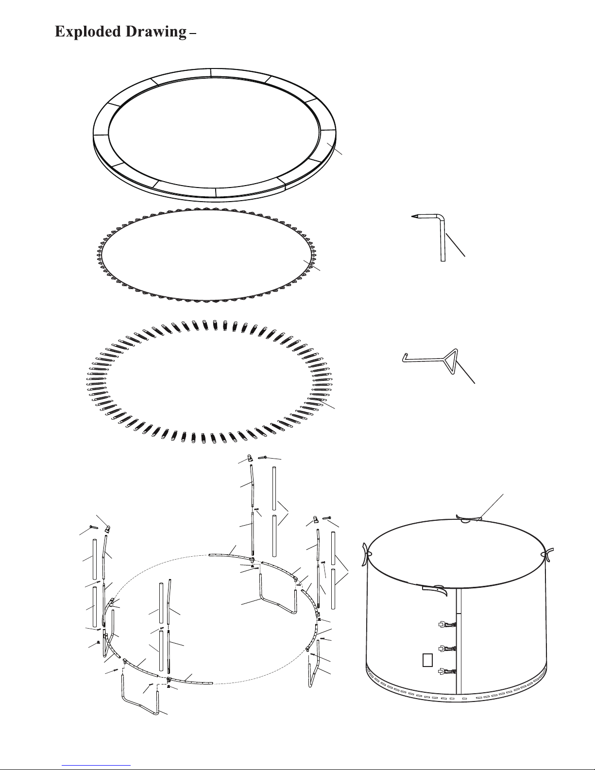
2Top Tube with T-joint (4 pcs) Top Tube with Socket (4 pcs)
5
Jumping mat (1 pc)
6
Frame pad (1 pc)
4
Leg brace (4 pcs)
7
Enclosure net (1 pc)
10 Curved Tube (4 pcs) 13 End Cap (4 pcs)
Spring Tool (1 pc)
Screw Driver (1 pc)
14 M5x50mm Bolt (4 pcs)
M4.8x16mm Self-tapping
Screw(14 pcs), 2 spare parts
11 Foam (8 pcs)
12 Pole Cap (4 pcs)
8
Spring (56 pcs)
9Straight Tube(4 pcs)
Use below drawings to identify all the parts.
12
15 16
SWTC811
2
2
2
2
2
1
1
1
1
6
6
6
6
7
7
777
7
7
7
9
10
13
14
12
14
14
12
7
7
7
4
3
5
16
15
8
9
9
9
10
10
10
12
11
11
11
11
13
13
13
11
11
7
13
SWTC811
Key No. Qty. Description
1 4 Top Tube with T-joint
2 4 Top Tube with Socket
3 1 Jumping mat
4 56 Spring
5 1 Frame pad
6 4 Leg Brace
7 14 M4.8x16mm Self-tapping Screw(2 spare parts)
8 1 Enclosure Net
9 4 Straight Tube
10 4 Curved Tube
11 8 Foam
12 4 Pole Cap
13 4 End Cap
14 4 M5x50mm Bolt
15 1 Spring Driver
16 1 Screw Tool
# 1 User’s Manual and Safety Placard
# 1 Set of ASTM Frame Labels
14
SWTC811

r.
• r.
•
1
2
T-joint
Socket
spring holes
face the ground
spring holes
face the ground
1. Locate the Top tube with T-joint(1) and the Top tube
with Socket(2) as shown.
NOTE:
Make sure all the spring holes are facing ground.
Horizontal square tube
(used to connect the Top tube)
Vertical round tube
(used to connect the Leg Brace)
T-joint
Horizontal square tube
(used to connect the Top tube)
Vertical round tube
(used to connect the Leg Brace)
Vertical square tube
(used to connect Enclosure pole)
Socket
If you don’t assemble in the right order, you will have to
disassemble the entire trampoline in order to attach correctly.
NOTE:
Identify the T-joint and Socket shown in right will
be helpful for you, they are pre-installed on Top tube.
1
15
14
14
Trampoline and Enclouse Assembly with Basketball Hoop

2. Press down on the Leg Brace (6) at the same
time and fully insert them into the
T-joint and Socket ,
then tighten by two M4.8x16mm Self-tapping
screws(7).
Repeat above assembly steps until six frame pieces
are completed.
then flip the trampoline frame pieces over so that the
legs are now holding the trampoline frame pieces up.
Locate two frame pieces as shown and then fully
connect them together.
T-joint
Socket
Socket
Repeat above step 3 in the same way, you should
now have a free standing frame as shown.
3.
T-joint
3
2
16
2
6
Push Here
Push Here
1
T-Joint
Socket
7
7
T-joint Socket
T-joint
T-joint
T-joint
SocketSocket
Socket

If the Enclosure net(8) and Jumping mat(3) are not
pre-installed, follow below steps to install.
Place the Jumping mat(8) on clear ground.
Identify the warning label on mat top and the ID
label on mat back as shown.
the first V-ring
clip
zipper loop
the first hole
Enclosure net
Enclosure door
Warning label (on mat top)
ID label (on mat back)
the first V-ring
the first hole
4.1
4.
Place the Enclosure net(8) on the Jumping mat(3),
make sure the first hole and the first V-ring are
aligned as shown.
4.2
Insert the first V-ring into the first hole, and then
insert the remaining V-rings into corresponding
holes in the same way one by one, until the Enclosure
Net(8) and the Jumping mat(3) are fully attached .
4.3
Enclosure door
Warning label (on mat top) ID label (on mat back)
Warning label (on mat top)
3
8
NOTE:
The first hole refers to the first one that is located just left
of the Enclosure door.
The first V-ring refers to the one that is located just
left of the warning label near the ID label on Jumping
mat.
4
17

If the Enclosure net and Jumping mat are pre-installed,
follow below steps to assemble the Jumping mat to frame.
5.1 Inspect the connection of Jumping mat and Enclosure
net, make sure all the V-rings are passed through the
corresponding net holes.
5.2 Place the Jumping mat(3) on clear ground inside the
frame. and then adjust the location of two warning
dacals to align the two T-joint in opposite direction
as shown.
the first V-ring
the first hole
5.3 Attach the first V-ring with a spring to the first spring
hole on left side of T-joint, and then attach the opposite
V-ring to the first spring hole on left side of T-joint.
NOTE:
Count exactly the quantity of V-rings and the spring holes
on frame top, make sure each of them are corresponding.
5.
the first spring hole
T-joint
left side
5
18
3
enclosure door
T-joint
Warning
Decal
Warning
Decal
T-joint
Enclosure
door
the first spring

Attach another two lateral V-rings to frame holes in the
same way as 5.2
Now there are 8 V-rings are attached to the Top tube.
And 8 Springs have been used.
V-ring
Frame
3
4
Attach the Spring as follows:
Hook one end of Spring (4) into the V-ring sewn on Jumping
mat (3).
Hook a Spring Tool as shown to the free end of the Spring.
Pull the Spring (4) until it reaches the frame.
There are 56 springs around the edge of Jumping mat(3)
and 56 holes around the top tube.
It is wise to wear leather gloves while attaching the springs.
Be careful where you place your hands as the Springs and
Frame joints can pinch.
A:
B:
C:
Push the end of the Spring (4) into a hole in the frame, then
unlook the Spring Tool
D:
NOTE:
CAUTION:
5.3
NOTE:
Count exactly the quantity of V-rings and the spring holes
on frame top, make sure each of them are corresponding.
Attach other V-rings to frame holes on left side of
T-joint or Socket in the same way as 5.2
5.4
19
3
T-joint
Enclosure door

Attach all the remaining V-rings with spring to
Top tube holes correspondlingly.
Enclosure door
Lay the Frame pad(5) on the frame. Adjust it’s
position so that the slits are just above the Sockets
as shown.
Do not use the trampoline without the Frame
Pad(5).The Frame Pad is designed to reduce
the possibility of injuries due to jumpers coming
in contact with the trampoline frame.
If you do not have a Frame Pad,contact your
dealer to obtain one.Properly install the Frame
Pad before using the trampoline.
5.5
T-joint
Socket
slit of pad
CAUTION:
6.
5
5
6
20
Table of contents
Other Skywalker Fitness Equipment manuals


Popular Fitness Equipment manuals by other brands

Tuff stuff
Tuff stuff CHR-500 owner's manual

Life Fitness
Life Fitness M051-00K73-A004 Assembly instructions

Life Span
Life Span MF3000 owner's manual

Life Span
Life Span CORTEX DBADJUST52.5PAIR manual

Body Craft
Body Craft Family Xpress instruction manual

Sport-Tiedje
Sport-Tiedje BodyCraft SW-F603 Assembly instructions


