Skyware Global 180 User manual

Assembly Instructions
Type 180 Antenna System
1.8 Meter Reflector with Az/El Cap Mount
8000352-03
Skyware Global
1315 Industrial Park Drive
Smithfield, NC 27577
Telephone: +1-919-934-9711
Internet: www.skywareglobal.com
Printed in U.S.A.
05/13 8000352-03 Rev D EC-01728

1
Skyware Global CORPORATION
VERY SMALL APERTURE TERMINAL (VSAT) PRODUCTS
TWELVE (12) MONTH LIMITED WARRANTY
Seller warrants that all Skyware Global manufactured VSAT products are transferred rightfully and with good title; that they are free from
any lawful security interest or other lien or encumbrance unknown to Buyer. Seller also warrants that for a period of twelve (12) months
from the date of shipment from Seller’s factory, all its VSAT products shall be free from defects in material and workmanship which arise
under proper and normal use and service. Buyer’s exclusive remedy hereunder is limited to Seller’s correction (either at its plant or at
such other place as may be agreed upon between Seller and Buyer) of any such defects by repair or replacement at no cost to Buyer,
except for the costs of any transportation in connection with the return of the defective VSAT products to be replaced or repaired, and
the costs to remove and/or reinstall the products, which shall be borne by Buyer. The limited warranty period shall not be extended
beyond its original term with respect to any part or parts repaired or replaced by seller hereunder.
This warranty shall not apply to VSAT products which (i) have been repaired or altered in any way so as to affect stability or
durability, (ii) have been subject to misuse, negligence or accident, (iii) have been damaged by severe weather conditions such as
excessive wind, ice, storms, lightning, or other natural occurrences beyond Seller’s control; (iv) have presented damages, defects or
nonconformances caused by improper shipping, handling or storage, and (v) have not been installed, operated or maintained in
accordance with Seller’s instructions.
Buyer shall present any claims along with the defective VSAT product(s) to Seller immediately upon failure Non-compliance with any
part of this warranty procedure may invalidate this warranty in whole or in part.
SELLER MAKES NO WARRANTY, EXPRESS OR IMPLIED, OTHER THAN AS SPECIFICALLY STATED ABOVE. EXPRESSLY EXCLUDED
ARE ANY IMPLIED WARRANTIES OF MERCHANTABILITY OR FITNESS FOR A PARTICULAR PURPOSE. THE FOREGOING SHALL
CONSTITUTE ALL OF SELLER’S LIABILITY (EXCEPT AS TO PATENT INFRINGEMENT) WITH RESPECT TO THE VSAT PRODUCTS. IN
NO EVENT SHALL SELLER BE LIABLE FOR ANY LOSS OF PROFITS OR REVENUE, LOSS OF USE, INTERRUPTION OF BUSINESS, OR
INDIRECT, SPECIAL, CONSEQUENTIAL OR INCIDENTAL DAMAGES OF ANY KIND AS A RESULT OF THE USE OF THE
PRODUCTS MANUFACTURED BY SELLER, WHETHER USED IN ACCORDANCE WITH THE INSTRUCTIONS OR NOT. UNDER
NO CIRCUMSTANCES SHALL SELLER’S LIABILITY TO BUYER EXCEED THE ACTUAL SALES PRICE OF THE VSAT PRODUCTS
HEREUNDER.
In some jurisdictions, Buyer may have other rights under certain statutes that may imply non-excludable warranties. No representative is
authorized to assume for Seller any other liability in connection with the VSAT products.
DATE DESCRIPTION REVISION
11/08 5079577 Rev A
03/10 725 Rev B
04/10 753 Rev C
05/13 EC-01728 Rev D
MANUAL REVISION HISTORY
WARRANTY
DO NOT DISCARD CONTENTS
The product in this packaging was placed in the market after August 13, 2005. Its components must not be discarded with
normal municipal or household waste.
Contact your local waste disposal agency for recovery, recycling, or disposal instructions.

INTRODUCTIONINTRODUCTION
INTRODUCTION
BOLT TORQUE
Exceptions To The Chart Above:
M12 x 100 Round Head Square Neck Bolt (20 ft-lb) (Securing Antenna to AZ/EL Cap)
M6 x 20 Hex Head Bolt (4 ft-lb) (Securing Clamp to Junction Block)
M6 x 30 Hex Head Bolt (4 ft-lb) (Securing Side Feed Legs to Junction Block and Antenna)
DIN Class 5.6
M6 M8 M12 M16 M20 M22
5 N-m 15 N-m 51 N-m 125 N-m 168 N-m 230 N-m
4 ft-lb 11 ft-lb 32 ft-lb 38 ft-lb 92 ft-lb 124 ft-lb
DIN Class 8.8
M8 M12 M16
24 N-m 90 N-m 203 N-m
18 ft-lb 66 ft-lb 150 ft-lb
HARDWARE SORTER
ITEM 2
M12 x 100 mm
Round Head
Square Neck Bolt
ITEM 17
M12 x 25 mm
Round Head
Square Neck Bolt
ITEM 38
M6 x 20 mm
Round Head
Square Neck Screw
ITEM 26
M6 x 20 mm
Hex Head
Cap Screw
ITEM 31
M6 x 30 mm
Hex Head
Cap Screw
Note: Hardware illustrations are actual size.
Place hardware on top of illustration to identify.
Shipping cartons should be unpacked and contents checked for damaged or missing parts. Should there be any parts
that are damaged or missing, contact Skyware Global at the location on the front of this manual.
UNPACKING AND INSPECTION
This manual covers the assembly and installation of the Skyware Global 1.8 m SMC offset antenna system. Read this
manual thoroughly before beginning assembly. For best results in the assembly process, perform each step in the same
sequence as listed in this manual.
2

3
SITE SELECTION
The main objective of conducting a site survey, utilizing a compass and clinometer, is to choose a mounting location on the
roof or ground that will give you the greatest amount of swing for azimuth and elevation for present as well as future use.
A pre-installation site survey is strongly recommended because it can alert you to any “look angle”, soil, or other problems.
The first and most important consideration when choosing a prospective antenna site is whether or not the area can provide
an acceptable “look angle” at the satellite. A site with a clear, unobstructed view facing south, southeast or southwest is
required. Your antenna site must be selected in advance so that you will be able to receive the strongest signal available.
Also consider obstructions that may occur in the future such as the growth of trees. It is important to conduct an on-site sur-
vey with a portable antenna or with a compass and clinometer to avoid interference, obstructions, etc.
When selecting “look angle”, be sure to observe and take readings approximately 10° to the left and right, above and
below your selected “look angle”. Before digging is done, information regarding the possibility of underground telephone
lines, power lines, storm drains, etc., in the excavation area should be obtained from the appropriate agency.
Because soils vary widely in composition and load capacity, consult a local professional engineer to determine the appro-
priate foundation design and installation procedure. A suggested foundation design with conditions noted is included in this
manual for reference purposes only (see page 4). To assist in the foundation design, refer to Antenna Wind loads in Appen-
dix A on page 14.
Before Roof Mount installation, it must be determined that the roof used for mounting the antenna is structurally sound. If
in doubt, have it checked by an architect or structural engineer. It is the customer’s responsibility that proper construction
techniques and applicable codes are adhered to. As with any other type of construction, a local building permit may be
required before installing an antenna. It is the property owner’s responsibility to obtain any and all permits.
INTRODUCTION
Recommendations for Site Selection, Assembly Tools Required for assembly, a Pre-installation Checklist and a hardware
sorter have been included in this section to help you prepare for installing the 1.8m Offset Antenna System.
Read this section to insure optimum antenna performance and to make the assembly and installation process as efficient as
possible by having the tools and materials at hand.
ASSEMBLY TOOLS AND PRE-INSTALLATION CHECKLIST
PRE-INSTALLATION CHECKLIST
All Installations:
o Grounding Rod Clamp and Grounding Block: As required by the National Electric Code or local electric code.
o Ground Wire: #10 solid copper or as required by the National Electric Code or local electric code. (Length
required)
o Coaxial Cable: (Size and length required)
Ground Pole Installations:
o Concrete: (See Ground Pole Section for quantity.)
o #3 Rebar: (See Ground Pole Section for quantity.) Deformed steel per ASTM A615, Grade 40 or 60.
REQUIRED ASSEMBLY TOOLS
1 - Compass 1 - Torque Wrench 1- 0 mm Nut Driver
1 - Precision Clinometer 1 - Ratchet Wrench (13 mm or 1/2” Drive) 1- 0 mm Box/Open End Wrench
1 - 228 mm or 9” Magnetic Level 1 - 19 mm or 3/4” Socket (1/2” Drive)
1 - Phillips Screwdriver 1 - 19 mm or 3/4” Deep Socket (1/2” Drive)
(For bottom two Round Head Square Neck
Bolts securing Antenna to AZ/EL Cap)

4
POLE SPECIFICATIONS
Ground Pole - 4.50 O.D. SCH 40 (4.026 I.D.) Steel - (Metric = 114.3 O.D. x 102.3 I.D. mm)
NOTE:
1. Poles are not supplied (purchased locally to ASTM A501) and must be field drilled 5/8” Dia (15.9mm) for M10 #3 rebar, drilled
.218 (5.55mm) for 1/4 - 20 self tapping grounding screw and galvanized or painted for protection.
2. Pole and foundation design based on the following criteria:
a. Uniform building code Exposure C and 1.5 stability factory.
b. Vertical soil pressure of 2000 pounds per square foot. (9765 Kilograms/meter square).
c. Lateral soil pressure of 300 pounds per square foot. (145 Kilograms/meter square).
d. Concrete compressive strength of 2500 pounds per square inch (176 Kg/Cm2) in 28 days.
CAUTION: The foundation design shown does not represent an appropriate design for any specific locality, since soil conditions vary and
may not meet design criteria given in Note 2. You should consult a local professional engineer to determine you soil conditions and
Appropriate foundation.
GROUND POLE INSTALLATION
114 mm
(4.5 in O.D.)
L
#3 rebar x 10 in
(9.5 rebar x 254 mm)
Insert through hole in
tube and center.
#3 Rebar
C
Minimum
Diameter
25 mm
to 51 mm
(1” to 2”) slope
for water run-off
Grade
Below
Frost Line
25 mm to 51 mm (1” to 2”)
slope for water run-off
Grade
114 mm
(4.5 in O.D.)
C
Minimum
Diameter Below
Frost Line
Approx.
51 mm
(2 in)
1676 mm
(66 in) (See Note)
#3 rebar x .46 m (18”)
(9.5 rebar x 457 mm)
Insert through
hole in tube and center.
#3 Rebar
(6)#3 rebar x .6 m (24 in)
(9.5 x 610 mm)
at 60˚ apart (See note)
51 mm
(2 in)
Bubble
Level
Ground Pole Must Be
Vertical in All Directions
at Top
NOTE:
127 cm (50”) may
be increased to frost
line. Concrete and
length of rebar will
increase
accordingly.
Bottom View
Pier Foundations Deep Frost Line Foundations
Reflector Size: 1.8 m
Concrete Dimension
L A B C E
2438 mm 1270 mm 1359 mm 914 mm 424 mm
(96 in) (50 in) (53 in) (36 in) 16.7 in
Concrete Volume: .84 m3 (1.1 yd3)
*NOTE: Clearance increases at elevations greater than 23˚
A
B
*E (See Note)
Fill Completely
with Concrete
Reflector Size: 1.8 m
Concrete Dimension
L A D C
2438 mm 1359 mm 1092 mm 737 mm
(96 in) (53 in) (43 in) (29 in)
Concrete Volume: .72 m3 (.94 yd3)
*NOTE: 1676 mm (66 in) may be increased, concrete
and length of rebar will increase accordingly.
L
A
D
Fill Completely
with Concrete
Soil conditions vary and you should consult with a local professional engineer for modifications, if any, to suit local soil
conditions and code requirements.
Designs based on allowable vertical soil bearing pressure of 2000 psf and 125 mph wind velocity. Minimum compressive
Strength of concrete shall be 2500 psi at 28 days.
DESIGNS SHOWN BELOW DO NOT REPRESENT AN APPROPRIATE FOUNDATION FOR ANY
SPECIFIC LOCALITY OR ANTENNA INSTALLATION. THEY ARE PROVIDED FOR
REFERENCE PURPOSES ONLY.

5
ASSEMBLY AND INSTALLATION
NOTE: 10mm tools fit M6 hardware. Recommendations for Site Selection, Assembly Tools Required for Assembly,
a Pre-Installation Checklist and a Hardware Sorter are provided in this manual for your convenience.
The AZ/EL cap can be installed on a ground pole or roof mount support. Mount should be assembled and in place, or
ground pole set, before installing the AZ/EL cap.
NOTE: For ground pole installations, allow concrete to cure before proceeding with installation.
FIGURE 1.0 FIGURE 1.1
M12 LOCK WASHER
4 PLACES M12
HEX NUT
4 PLACES
TOP/BOTTOM
ANGLE
2 PLACES
RD HD
SQ NK
BOLT
M12 x 25mm
4 PLACES
AZ/EL
Cap
ELEVATION
ADJUSTMENT
BOLT
AZIMUTH
LOCKING
BOLTS
AZIMUTH
FINE TUNING
ADJUSTMENT
BOLT
6
3
2
17
7A
6
2
3
1
2
3
ASSEMBLY AND INSTALLATION
AZ/EL FRAME ASSEMBLY (FIGURE 1.0)
Assemble top/bottom angles (6), to housing frame (7A)
with M12 x 25mm round head square neck bolts (17),
lock washers (2), and hex nut (3), as shown in Figure 1.0.
M12 hex nuts (3), must be finger tight.
INSTALLING AZ/EL CAP ON GROUND POLE
Back out (do not remove) the four azimuth locking bolts
from AZ/EL cap. Install cap onto top of ground pole or
base tube. To hold the AZ/EL cap in place while installing
antenna, temporarily tighten one of the azimuth locking
bolts.
INSTALLING ANTENNA TO AZ/EL CAP
Insert M12 x 100mm round head bolts (1) into antenna
mounting holes, as shown in Figure 1.1. Lift antenna and
align mounting bolts with holes in AZ/EL cap. Secure with
M12 lock washers (2) and hex nuts (3). Torque to 20 ft-lbs
(27 N-m).
IMPORTANT: For correct orientation of antenna, the
“UP” arrow must be as shown in Figure 1.1 and
Figure 1.2.
After M12 x 100mm antenna bolts are torqued, then
torque top/bottom angle bolts (17) and hex nuts (3) to 38
ft-lbs (51 N-m).
5
NOTE: 10mm tools fit M6 hardware. Recommendations for Site Selection, Assembly Tools Required for Assembly, a
Pre-Installation Checklist and a Hardware Sorter are provided in this manual for your convenience.
The AZ/EL cap can be installed on a ground pole or roof mount support. Mount should be assembled and in place, or
ground pole set, before installing the AZ/EL cap.
NOTE: For ground pole installations, allow concrete to cure before proceeding with installation.
AZ/EL FRAME ASSEMBLY (FIGURE 1.0)
Assemble top/bottom angles (6), to housing frame (7A)
with M12 x 25mm round head square neck bolts (17),
lock washers (2), and hex nut (3), as shown in Figure
1.0. M12 hex nuts (3), must be finger tight.
INSTALLING AZ/EL CAP ON GROUND POLE
Back out (do not remove) the four azimuth locking bolts
from AZ/EL cap. Install cap onto top of ground pole or
base tube. To hold the AZ/EL cap in place while install-
ing antenna, temporarily tighten one of the azimuth
locking bolts.
INSTALLING REFLECTOR TO AZ/EL CAP
Insert M12 x 100mm round head bolts (1) into Reflector
mounting holes, as shown in Figure 1.1. Lift Reflector and
align mounting bolts with holes in AZ/EL cap. Secure
with M12 lock washers (2) and hex nuts (3).Torque to 20
ft-lbs(27 N-m).
IMPORTANT: For correct orientation of
Reflector, the“UP”arrow must be as shown in
Figure 1.1 and Figure 1.2.
After M12 x 100mm Reflector bolts are torqued, then
torque top/bottom angle bolts (17) and hex nuts (3) to
38ft-lbs (51 N-m).

6
FEED & FEED LEGS INSTALLATION
Refer to Manufacturer’s Instructions packed with feed to as-
semble and install feed assembly.
Insert bottom feed leg (33) into clamp (39) and align hole in
feed leg with alignment pin inside clamp. Install bottom feed
leg (33) with clamp (39) onto bottom edge of antenna, se-
curing with two M6 x 20mm round head square neck bolts,
lock washers and hex nuts (35, 36 and 38). Do not tighten.
NOTE: Bottom feed leg is the one with open
round ends on both ends and a lance on one
end and alignment hole in opposite end. Insert
end with hole into bottom feed leg clamp (39).
Install side feed legs (30) to sides of antenna (37) as shown
in Figure 1.2. Secure with M6 x 20mm hex bolt, lock
washer and hex nut (34, 35 and 36). Do not tighten.
Insert one side feed leg (30) into junction block (29) and
secure with M6 x 30mm hex bolt and flat washer (31 and
32). Do not tighten.
Insert bottom feed leg (33) into junction block (29) until
lance on leg is engaged.
Insert opposite side feed leg (30) into junction block (29)
and secure with M6 x 30mm hex bolt and flat washer (31
and 32).
IMPORTANT: Tighten and torque hardware
securing side feed legs and bottom feed leg
to junction block and antenna to 4 ft-lbs (5.4
N-m).
Refer to Manufacturer’s Instructions to assemble and install
feed assembly.
Use bottom feed leg as conduit and route coaxial cable up
thru leg. Leave approximately 12” of length beyond junction
block. Install “F” connector onto cable for assembly to LNB.
NOTE: OTHER FEED ASSEMBLIES MAY USE DIF-
FERENT FEED LEGS. REFER TO SUPPLEMENTAL
INSTRUCTIONS PACKED WITH THE FEED LEGS.
PARTS AND HARDWARE
FIG. 3.2 - KU FEED SUPPORT LEGS
NO. DESCRIPTION QTY.
28 CLAMP 1
29 JUNCTION BLOCK 1
30 SIDE FEED LEG 2
31 HEX HD BOLT M6 X 30mm 2
32 FLAT WASHER,1/4” x 3/4” O.D., S.S. 2
33 BOTTOM FEED LEG 1
34 HEX BOLT M6 x 20mm 2
35 LOCK WASHER, M6, S.S. 4
36 HEX NUT, M6, S.S. 4
NO. DESCRIPTION QTY.
38 RD HD-SQ NK BOLT, M6 x 20mm, S.S. 2
39 CLAMP, BOTTOM FEED LEG 1
*
*
*Supplied with Feed Assembly
FIG. 1.2 - INSTALLING FEED AND FEED SUPPORT LEGS TO ANTENNA

ASSEMBLY ALIGNMENT PROCEDURE
7
Alignment with the satellite is obtained by setting polarization,
elevation, and azimuth. Charts 1, 2 and 3 are to determine the
values for your earth station antenna site. “∆L” is the difference
between the earth station antenna site longitude and the satellite
longitude. Use “∆L” and your earth station latitude to obtain
polarization, elevation or azimuth setting.
Elevation Alignment
Refer to Chart 1 to determine your elevation setting.
IMPORTANT: Before adjustment, loosen the two
bolts (13) (18) on each side of this housing (1/2
turn). Re-tighten all four bolts after adjustment is
completed.
Turn elevation adjustment bolt, Item 9, clock-wise, to decrease
elevation, and counterclockwise to increase elevation. Align the
edge of bracket with the appropriate mark at the desired eleva-
tion reading (See Figure 2.0).This will be an approximate setting.
Optimum setting will be achieved when Fine Tuning. Refer to
Figure 2.3.
NOTE: When the reflector face is vertical,while
the beam elevation (beam) axis is 22.62°,the
offset angleof the antenna.(See Appendix,Outline
Drawing,Page 14).
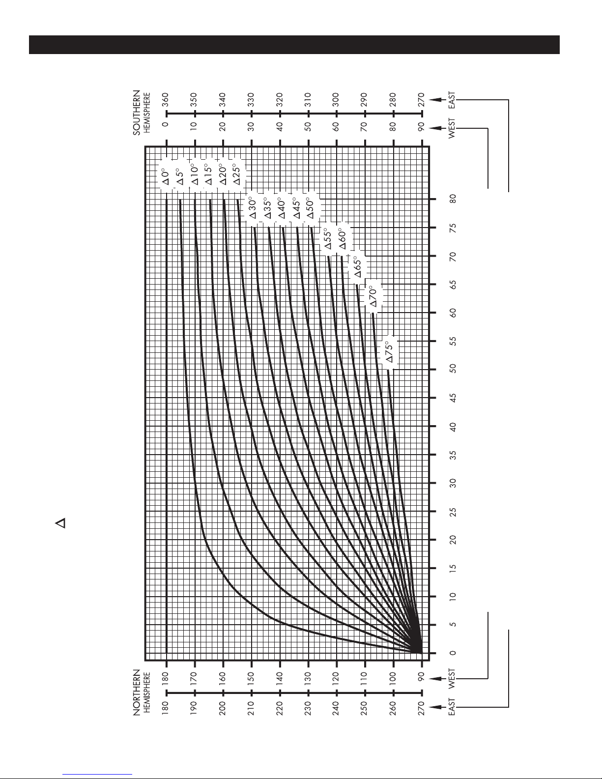
Azimuth Alignment
Use Chart 3 and determine your azimuth setting. Values in
chart must be adjusted for magnetic deviation for
your location for correct compass reading. Equally
tighten the four azimuth locking bolts (15) until snug, and back off
1/8 turn. This will allow azimuth rotation with slight resistance,
without AZ/EL cap tilting on pole. Rotate the reflector and AZ/EL
cap, pointing it to the correct compass reading for your location
and satellite. Refer to Figure 2.1. If desired signal is not found,
increase or decrease elevation setting and repeat the azimuth
sweep until desired signal is found. Tighten progressively (1/8
turn each) all four azimuth bolts (15).Repeat until 70-80 ft-lbs (95-
108 N-m) torque is reached.
Fine Tuning
Snug tighten hex bolt/nut in curved slots (13) and pivot bolts (18)
(refer to Figure 2.0). Use a signal strength measuring device for
final adjustments to obtain maximum antenna performance. Alter-
nate between elevation and azimuth fine tuning to reach maxi-
mum signal strength, until no improvement can be detected. Top
plate locking bolts (18), 4 places, should be torqued to 6-8 ft-lbs
(8-11 N-m). See Figure 2.3. Turn the azimuth adjusting nuts (3)
clockwise or counter clockwise for azimuth fine tuning. Tighten
and torque all hardware(refer to Torque Chart on Page 2).
Polarization of Feed
Loosen two feed horn clamp bolts (26) and turn feed clockwise
or counterclockwise, depending on being east or west of the sat-
ellite as shown on Chart 3. Align marks on the horn clamp and
appropriate mark on the horn scale. Polarization chart assumes
antenna system polarization is Tx vertical and satellite vertical Pol
is perpendicular to plane of geostationary arc. For horizontal Tx
of antenna, feed must be rotated 90° from values shown. Start-
ing point for polarization adjustment is 0°, as shown in figure
2.0. Tighten and torque clamp bolts to 4 ft-lbs (5.4 N-m), after
setting.
ANTENNA ALIGNMENT PROCEDURE
Alignment with the satellite is obtained by setting polarization, ele-
vation and azimuth. Charts 1, 2 and 3 are to determine the values
for your earth station antenna site. “∆L” is the difference between the
earth station antenna site longitude and the satellite longitude. Use
“∆L” and your earth station latitude to obtain polarization, elevation
or azimuth setting.
Elevation Alignment
Refer to Chart 1 to determine your elevation setting. IMPORTANT:
Before adjustment, loosen the two bolts (13) (18) on each side
of this housing (1/2 turn). Re-tighten all four bolts after adjust-
ment is completed. Turn elevation adjustment bolt, Item 9, clock-
wise, to decrease elevation, and counterclockwise to increase ele-
vation. Align the edge of bracket with the appropriate mark at the
desired elevation reading (See FIgure 2.0). This will be an approxi-
mate setting. Optimum setting will be achieved when Fine Tuning.
Refer to Figure 2.3. NOTE: When the reflector face is vertical,
while the beam elevation (beam) axis is 22.62˚, the offset angle
of the antenna. (See Appendix, Outline Drawing, Page 14).
Azimuth Alignment
Use Chart 3 and determine your azimuth setting. Values in chart
must be adjusted for magnetic deviation for your location for
correct compass reading. Equally tighten the four azimuth locking
bolts (15) until snug, and back off 1/8 turn. This will allow azimuth
rotation with slight resistance, without AZ/EL cap tilting on pole.
Rotate the reflector and AZ/EL cap, pointing it to the correct com-
pass reading for your location and satellite. Refer to Figure 2.1. If
desired signal is not found, increase or decrease elevation setting
and repeat the azimuth sweep until desired signal is found. Tighten
progressively (1/8 turn each) all four azimuth bolts (15). Repeat until
70-80 ft-lbs (95-108 N-m) torque is reached.
Fine Tuning
Snug tighten hex bolt/nut in curved slots (13) and pivot bolts (18)
(refer to Figure 2.0). Use a signal strength measuring device for final
adjustments to obtain maximum antenna performance. Alternate
between elevation and azimuth fine tuning to reach maximum signal
strength, until no improvement can be detected. Top plate locking
bolts (18), 4 places, should be torqued to 6-8 ft-lbs (8-11 N-m). See
Figure 2.3. Turn the azimuth adjusting nuts (3) clockwise or coun-
terclockwise for azimuth fine tuning.Tighten and torque all hardware
(refer to Torque Chart on Page 2).
Polarization of Feed
Loosen two feed horn clamp bolts (26) and turn feed clockwise or
counterclockwise, depending on being east or west of the satellite
as shown on Chart 3. Align marks on the horn clamp and appropri-
ate mark on the horn scale. Polarization chart assumes antenna
system polarization is Tx vertical and satellite vertical Pol is per-
pendicular to plane of geostationary arc. For horizontal Tx of anten-
na, feed must be rotated 90˚ from values shown. Starting point for
polarization adjustment is 0˚, as shown in figure 2.0. Tighten and
torque clamp bolts to 4 ft-lbs (5.4 N-m), after setting.
ALIGN THIS EDGE
WITH SCALE FOR
ELEVATION
READING
ELEVATION ADJUSTING
BOLT (9) ELEVATION
LOCKING
BOLT (13)
ELEVATION
PIVOT
BOLT (18)
AZIMUTH LOCKING
BOLTS (15)
EXAMPLE SHOWN
AT 22.6 DEGREES
AZIMUTH
-40 +40
0
26
ALIGNMENT
MARK
ARROW
FIG. 2.0 - SETTING ANTENNA ELEVATION
FIG. 2.1 - ROTATING ANTENNA FOR AZIMUTH
FIG. 2.2 - POLARIZATION OF FEED
AZIMUTH
ADJUSTING
NUTS (3)
AZIMUTH
ADJUSTING
SCREW (24)
ADJUSTING
SCREW (21)
PIVOT BOLT
AZIMUTH
LOCKING
BOLTS (15)
TOP PLATE
LOCKING
BOLTS (18)
FIG. 2.3 - AZ/EL CAP MOUNT w/AZ
FINE TUNE

GROUNDING
ALL INSTALLATIONS TO CONFORM TO
THE LATEST ISSUE OF THE
NATIONAL ELECTRIC CODE.
8
Ground pole, antenna mount assembly and feed cables must be grounded in accordance with current National Electric Code
and local electric codes to protect from surges due to nearby lightning strikes.
Clamps that provide a solid connection between ground wire and ground source should be used.
GROUNDING
ALL INSTALLATIONS TO CONFORM TO
THE LATEST ISSUE OF THE
NATIONAL ELECTRIC CODE.
Ground pole, antenna mount assembly and feed cables must be grounded in accordance with current National Electric
Code and local electric codes to protect from surges due to nearby lightning strikes.
Clamps that provide a solid connection between ground wire and ground source should be used.
GROUND WIRE
(Typical #10 AWG Copper, #8 Aluminum)
Refer to NEC Section 810 and local electric
codes for the specific area requirements.
¹⁄₄" - 20 UNC x ⁵⁄₈"
HEX HEAD, TYPE "D" POINT,
SELF TAPPING SCREW
GROUND LUG
¹⁄₄" EXTERNAL TOOTH
LOCK WASHER
Drill hole through one wall with
⁷⁄₃₂" (5.5mm) Dia. twist drill.
Apply sealant here, after
assembly, to improve
corrosion resistance.
GROUND POLE
REF
10"-12"
38"
APPROX.
TYPICAL ELECTRICAL GROUNDING
FOR ANTENNA GROUND POLE
50
125
120
115
110
105
100
95
90
85
80
75
70
65
50
47.5
45
42.5
40
37.5
35
32.5
30
27.5
25
47.5
45
42.5
40
37.5
35
32.5
30
27.5
25
LATITUDE/LONGITUDE CHART
GROUNDING FEED CABLES
Ground Wire
(NEC Section
810-20)
Ground Block
(NEC Section
810-20)
Coaxial Cables (To Receiver)
Coaxial
Cables
(From LNB)
GROUNDING FEED CABLES
GROUNDING
8
ALL INSTALLATIONS TO CONFORM TO
THE LATEST ISSUE OF THE
NATIONAL ELECTRIC CODE.
Ground pole, antenna mount assembly and feed cables must be grounded in accordance with current National Electric
Code and local electric codes to protect from surges due to nearby lightning strikes.
Clamps that provide a solid connection between ground wire and ground source should be used.
GROUND WIRE
(Typical #10 AWG Copper, #8 Aluminum)
Refer to NEC Section 810 and local electric
codes for the specific area requirements.
¹⁄₄" - 20 UNC x ⁵⁄₈"
HEX HEAD, TYPE "D" POINT,
SELF TAPPING SCREW
GROUND LUG
¹⁄₄" EXTERNAL TOOTH
LOCK WASHER
Drill hole through one wall with
⁷⁄₃₂" (5.5mm) Dia. twist drill.
Apply sealant here, after
assembly, to improve
corrosion resistance.
GROUND POLE
REF
10"-12"
38"
APPROX.
TYPICAL ELECTRICAL GROUNDING
FOR ANTENNA GROUND POLE
50
125
120
115
110
105
100
95
90
85
80
75
70
65
50
47.5
45
42.5
40
37.5
35
32.5
30
27.5
25
47.5
45
42.5
40
37.5
35
32.5
30
27.5
25
LATITUDE/LONGITUDE CHART
GROUNDING FEED CABLES
9
POLARIZATION CHART
EARTH STATION LATITUDE IN DEGREES NORTH OR SOUTH OF EQUATOR
FEED ROTATION
(Facing Antenna)
For + Polarization Rotate Counter Clockwise
For - Polarization Rotate Clockwise
Antenna
Polarization Chart Sign Values (+ or -) Northern Hemisphere Southern Hemisphere
Antenna Site West of Satellite Longitude - +
Antenna Site East of Satellite Longitude + -
Feed

10
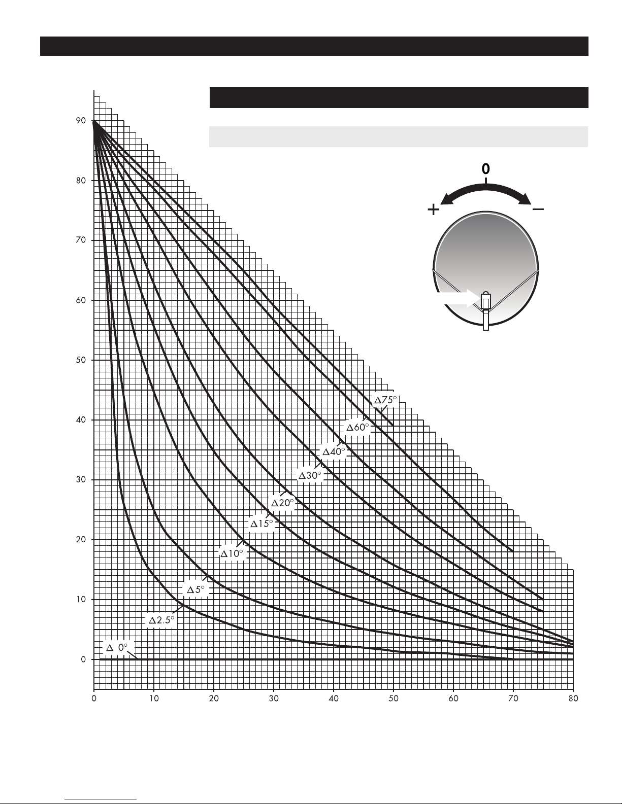
ELEVATION CHART
Use of Elevation Chart
n Determine = the difference between your site longitude and the satellite
longitude.
n Find you latitude on horizontal axis.
n Follow your latitude up until you intersect the curve for your .
n Read Elevation value on vertical axis.
ELEVATION IN DEGREES
11
ANTENNA ALIGNMENT PROCEDURE
“ “ IS THE DIFFERENCE BETWEEN THE EARTH STATION
ANTENNA SITE LONGITUDE AND THE SATELLITE LONGITUDE
EARTH STATION ANTENNA AZIMUTH IN DEGREES
EARTH STATION ANTENNA AZIMUTH IN DEGREES
EARTH STATION ANTENNA LATITUDE IN DEGREES NORTH OR SOUTH OF EQUATOR
AZIMUTH COLUMN READING WHEN EARTH STATION IS WEST OF SATELLITE
AZIMUTH COLUMN READING WHEN EARTH STATION IS EAST OF SATELLITE
AZIMUTH CHART

12
PARTS & HARDWARE
NO. DESCRIPTION QTY.
1 RD HD SQ NK BOLT, M12 x 100mm, GALV. 4
2 LOCK WASHER, M12 16
3 HEX NUT, 1/2” , GALV., M12 17
4 SPLIT PIN, M3.2 x 25mm 1
6 TOP/BOTTOM ANGLE 2
7 BACKFRAME HOUSING ASSEMBLY 1
8 FLAT WASHER - M12 7
9 HEX HD SCREW, SPCL, M12 x 210mm 1
10 SPHERICAL WASHER 1
11 CASTLE NUT, M12 1
12 SWIVEL NUT, M12 1
1
PARTS AND HARDWARE
1
23
14
13
18
28
17
6
7
2
3
20
8
2
3
2
36
9
810
11
4
12 3
2
8
18
3
3
19
24
16
23
22
15
2
18
21
FIG. 3.0 - AZ/EL CAP
NO. DESCRIPTION QTY.
13 HEX HD BOLT, M12 x 25mm 1
14 LABEL, ELEVATION 1
15 HEX HD BOLT, M12 x 30mm 4
16 CANISTER WELDMENT 1
17 RD HD SQ NK BOLT, M12 x 25mm 4
18 RD HD SQ NK BOLT, M12 x 35mm 7
19 FLAT WASHER - LARGE 2
20 SPRING PIN, M8 X 20mm 1
21 HEX HD BOLT, M8 X 25mm 1
22 LOCK WASHER M8 1
23 HEX NUT M8 1
24 BOLT, SPADE M12 x 135mm 1

13
PARTS & HARDWARE

14
APPENDIX A
Outline Drawing
Type 180 1.8m Offset SMC Reflector with Rx Mount
(197.2cm)
77.6in
(182.2cm)
71.7in
(141.0cm)
55.5in
(239.5cm)
94.3in
(39.6cm)
15.6in
(171.5cm)
67.5in
22.6
O
(38.1cm)
15in
ANTENNA
L
C
MECH. AXIS
BEAM AXIS
(151.1cm)
59.5in
(183.8cm)
72.4in
22.6
O
12.6
O
L
C
MECH. AXIS
BEAM AXIS
L
C
POLE
HORIZONTAL ANTENNA
(8.9cm)
3.5in
(31.0cm)
12.2in
10.0
O
L
C
POLE
(64.0cm)
25.2in
(114.3mm)
4.5in O.D.
Type 180 1.8m Antenna System with AZ/EL Cap Mount
NOTES: Dimensions shown are for ground pole (4.50” D.D. Schedule 40, Fy = 50KSI) or 4”, Pipe SCH 80,
Fy = 36KSI (4.5” O.D. x 3.83 I. D.) Purchased locally
METRIC GROUND POLE DIMENSIONS
114.3mm O.D. x 97.3mm I.D. Fy = 248 Mpa

15
L
APPENDIX B
1.8m ANTENNA SURVIVAL WINDLOADS AT 125 MPH VELOCITY
ELEVATION FORCE MOMENTS
DEGREES (POUNDS)* (FOOT-POUNDS)**
MECH. BEAM FHFVMTMO
0 23 1824 -47 1073 8,436
10 33 1726 -365 1035 7,983
20 43 1677 -710 984 7,756
30 53 1519 -1008 892 7,025
40 63 1337 -1215 756 6,184
50 73 1166 -1337 635 5,393
60 83 972 -1398 491 4,496
70 93 729 -1082 378 3,372
MoBASED ON 55.5” FROM MOUNTING SURFACE TO C OF ANTENNA.
*kg = Pounds x .45359
** N.m = Foot-Lbs. x 1.35582
Values shown above represent maximum forces for any wind direction.
Height and exposure factors from the uniform building code are NOT included.
FIG. 4.0

To ensure peak performance of the antenna system and to maintain validity of the warranty, the user should perform a
periodic inspection every 6 months or following any severe weather event, As a minimum the following items should be
inspected.
1. Installation Mount
Check for loose hardware - tighten if necessary.
Check integrity of anchor bolts or hardware securing mount to the building or foundations
Check ballast of Non-Penetrating Roof Mounts - cracked or broken blocks must be replaced.
Check hardware and structural members for signs of corrosion - repair or replace as needed
2. Antenna Back Structure or Az/El Mount
Check for loose hardware - tighten if necessary.
Check for signs of structural damage such as bending or cracking
Check hardware and stuctural members for signs of corrosion - repair or replace as needed
3. Reector
Check intergrity of bolts securing reector to back structure or az/el mount. Tighten any loose hardware.
Check for signs of damage such as cracking. Inspect reector face for impact damage.
Check hardware for signs of corrosion - repair or replace as needed.
4. Feed Support Structure
Check for loose hardware - tighten if necessary.
Check for signs of structural damage such as bending.Check hardware and stuctural members for signs of corrosion -
repair or replace as needed
5. Feed & RF Components
Check for loose hardware - tighten if necessary.
Check hardware for signs of corrosion - repair or replace as needed.
Check feed lens or window for damage or signs of leaking.Check waveguide connections between feed and RF electronics
6. Electrical
Check for loose cables and connectors - tighten if necessary
Check for tight grounding connections
Check cables for weathering or cracks
PERIODIC INSPECTION & MAINTENANCE
INSTALLATION MOUNT
ANTENNA BACK STRUCTURE OR AZ/EL MOUNT
REFLECTOR
FEED SUPPORT STRUCTURE
FEED & RF COMPONENTS
ELECTRICAL
16
Table of contents
Other Skyware Global Antenna manuals

Popular Antenna manuals by other brands

Betso
Betso Sharkie user manual

Directive Systems & Engineering
Directive Systems & Engineering DSE2455LYK Assembly

KVH Industries
KVH Industries TracVision TV3 installation guide

CommScope
CommScope F-042-GL-E instruction sheet

COBHAM
COBHAM Sea Tel 4010W-33 installation manual

Lorex
Lorex ACCANT08 quick start guide


