Betso Sharkie User manual

User manual
BETSO SHARKIE
Active antenna with extremely low noise and easy gain adjustment
1© Copyright BETSO ELECTRONICS Ltd.
User manual
BETSO SHARKIE
Contents
1. Product description................................................................................................3
2. Top features.......................................................................................................... 3
3. Control elements.................................................................................................... 4
4. Power supply......................................................................................................... 4
5. Turning on............................................................................................................5
6. Setting of antenna gain in the range 9 to +18 dB...................................................5
7. Setting of right gain value to get the best performance.............................................5
8. Display settings...................................................................................................... 6
9. Recommended accessories......................................................................................6
10. Troubleshooting...................................................................................................7
11. Safety instructions................................................................................................7
12. Technical specifications.........................................................................................7
13. Schematic of connector........................................................................................8
14. Table of common coaxial cables attenuation...........................................................8
15. EC Declaration of conformity................................................................................9
Used symbols
Indicates text that has only in ormative character. I you overlook this
in ormation, it can't result in product damage by it's mishandling.
Indicates text that has important instruction character. I you overlook this
in ormation, it may result in product damage not covered by warranty.
© Copyright BETSO ELECTRONICS Ltd. 2

User manual
BETSO SHARKIE
Thank you that you have purchased the product BETSO!
Please pay su icient attention to the ollowing user manual o your new product
BETSO. Following these instructions, you will avoid the possible damages o your new
device and at the same time, they will be presented to you all the available eatures that
allow you to take advantage o the potential o the product.
For the latest in ormations about our products BETSO please contact your local
distributor or visit our website http://www.betso.eu.
1. Product description
The SHARKIE is our new compact, wideband UHF, active receiver antenna with
Log Periodic Dipole Array (LPDA) structure and cardioid directivity. It's extremely low
noise ampli ier with easy gain setting is ideal or variable coaxial cable length attenuation
compensation in the ield. Rock solid mechanical construction guarantees careless
unctionality both in indoor and outdoor locations.
. Top features
•Frequency range 470 MHz to 850 MHz
•Antenna structure average gain 8 dB (9dB peak)
•Ultra low noise onboard ampli ier with gain rom -9 dB to +18 dB
•Excellent RF parameters:
◦0.75 dB ampli ier IC NF
◦> 34 dBm IP3 point
◦< 1.2 V.S.W.R.
•High e icient input ilters or removing unwanted RF spectrum
•Plug and work, surprisingly easy to setup and put to work low
•Top build quality
•Easy gain setting with automatic last set gain storing
•Brightness o LED display can be automatically adjusted according to ambient light
•Brightness o LED display can be also set manually to requested level
•Display can be completely turned o with ability to show preset gain value upon
button request
3© Copyright BETSO ELECTRONICS Ltd.
User manual
BETSO SHARKIE
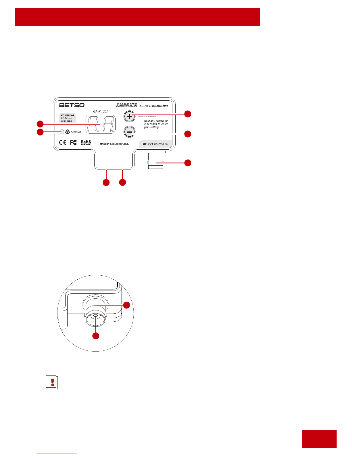
3. Control elements
4. Power supply
External power supply 5-20V DC has to be applied using coaxial cable connected to
the input BNC connector, which schematic is shown below.
Warning: Never insert power supply with voltage exceeding operating range o 5-
20V DC! Violation o this operating condition can lead to losing warranty and
destroying the device!
© Copyright BETSO ELECTRONICS Ltd. 4
1. Display
. Ambient light sensor
3. Button “UP”
4. Button „DOWN“
5. BNC output/powering
connector
6. 1/4“ mounting thread
7. 3/8“ mounting thread
2
7
1. GND
. 5-20V DC/Antenna signal
1
2
1
6
5
3
4

User manual
BETSO SHARKIE
5. Turning on
turning on antenna will turn on automatically upon power insertion
through coaxial cable
turning off to turn o antenna, simply remove coaxial cable or turn o DC
powering component on power source
Warning: Never insert power supply with voltage exceeding operating range o 5-
20V DC! Violation o this operating condition can lead to losing warranty and
destroying the device!
6. Setting of antenna gain in the range -9 to +18 dB
Antenna gain can be set in the range o -9 to +18 dB.
enter settings long (2 seconds) press o UP or DOWN buttons
change settings short press o UP or DOWN button
save settings i no button is pressed during 3 seconds, gain value stops to
lash and actual value is stored in memory
When the antenna is turned on, it will automatically recall last saved gain
settings.
7. Setting of right gain value to get the best performance
To get the best RF per ormance o your wireless system, setting of right value of
antenna gain is important. Allways start with setting the gain, which covers losses o
your coaxial cable. Losses o common types o coaxial cables are in the table on page 8.
I signal indicator on your receiver indicates very weak signal even i you set the
gain which covers coaxial cable losses, you can try to add more gain and get
better per ormance. For example in places with low RF noise this gain can add
multiple working distance o your wireless system.
5© Copyright BETSO ELECTRONICS Ltd.
Other Betso Antenna manuals

Popular Antenna manuals by other brands

DAVIS
DAVIS Windex AV 3160 installation instructions

Belden
Belden Hirschmann BAT-ANT-N-14G-IP23 Mounting instruction

Vtronix
Vtronix YHK Fitting instructions

KVH Industries
KVH Industries TracVision 6 Technical manual

Leica Geosystems
Leica Geosystems GS10 user manual

Sirio Antenne
Sirio Antenne Gain-Master manual


Feig Electronic
Feig Electronic ID ISC.ANTH200/200 Series manual

TERK Technologies
TERK Technologies TV44 owner's manual

TERK Technologies
TERK Technologies SIR3 owner's manual

Directive Systems & Engineering
Directive Systems & Engineering DSE2324LYRMK quick start guide

HP
HP J8999A instructions

MobilSat
MobilSat MSP-S Mounting instructions