SL TF1500 Series User manual

Page 1
TF1500 Application Note v1019 Copyright © 2019 SL Power Electronics Corp. All rights reserved.
TF1500 Family
Industrial Power Supplies
Single Output 1500 Watt
AN-P026
Industrial Power Supplies
Single Output 1500 Watt
TF1500 Family
TF1500 Application Note v1019 Copyright © 2019 SL Power Electronics Corp. All rights reserved. Page 2
OVERVIEW
Power supplies from the TF1500 Family offer single output AC to DC converters for industrial use. In addition to the wide AC input
voltage range 90VAC–264VAC it supports also DC input voltages 127VDC–370VDC. Intelligent fan control based on load and
temperature monitoring allows a reduce audible noise whenever the power level is low. Integration of latest technologies enables users
to benefit from two most advantageous features for power control in one unit: full range output voltage and/or full range output current
control, which offers great flexibility and user customization in many applications.
TF1500 series power supplies support RS 232/RS 485 UART control interface based on RXD/TXD TTL signals or I²C interface
based on serial clock (SCL) and serial data (SDA) signals. Both allow control of functions such as ON/OFF control, output current
limit and output voltage settings. With the same communication interfaces user can read out actual output voltage, output current,
internal temperature, status of the unit and manufacturing related data such as model name, serial number etc. To simplify digital
communication with the unit a graphical user interface (GUI) along with user control interface board CT-251 can be used.
For users without a host PC or for quick indication an intelligent 3 color LED reports the global status of the unit such as power OK, in
remote or local mode, standby, failure signals for overvoltage, overcurrent or overtemperature, fan failure and power failure. The exact
LED indication is listed in datasheets.
To achieve higher output power a synchronized array of several power supplies from TF1500 family may be connected in parallel. More
detailed information is described in “proper use” section of this document and in the datasheet.
TF1500 family is certified to EN 60950-1 and UL 60950-1 safety standards and complies with IEC61000-x EMI/EMC directives to allow
final equipment to meet industrial requirements. Contact your field application support for other standards.
This application note provides guidance for proper use, system design considerations and key performance data of TF1500 series
power supplies. Additional performance data is available upon request.
Data provided in the application note is for reference purposes and may not represent worst case conditions.
MODEL SELECTION
*All models are rated with 1500 Watt output power, ±1% line regulation and ±1% load regulation.
*Ripple & noise are measured at 20MHz of bandwidth by using a 12” twisted pair-wire terminated with a 0.1uF & 47uF parallel capacitor.
*Other output voltages available, consult your local technical support.
Model Number
2
Output Voltage Current Range Ripple & Noise
2
Efficiency
TF1500A12K 12.0V 125A 150mV pk-pk 89%
TF1500A15K 15.0V 100A 150mV pk-pk 90%
TF1500A24K 24.0V 62.5A 240mV pk-pk 92%
TF1500A48K 48.0V 31.3A 480mV pk-pk 92%
TF1500A60K 60.0V 25A 600mV pk-pk 93%

Industrial Power Supplies
Single Output 1500 Watt
TF1500 Family
TF1500 Application Note v1019 Copyright © 2019 SL Power Electronics Corp. All rights reserved. Page 3
The TF1500 AC-DC power supplies offer complete solution with intelligent fan control however users must consider proper installation
of the units. Pay attention to following specifications and design requirements to ensure correct operation of your TF1500 series power
supply.
Output Cable
Gauge (2 wire)
Max. allowed output cable length @500mV voltage drop
Output Current = 33.33A Output Current = 62.5A Output Current = 125A
12A WG 144.0 cm
56.7”
76.8 cm
30.2”
38.4 cm
15.1”
14A WG 90.5 cm
35.6”
48.3 cm
19.0”
24.1 cm
9.5”
16A WG 56.8 cm
22.4”
30.3 cm
11.9”
15.2 cm
6.0”
18A WG 35.7 cm
14.1”
19.0 cm
7.5”
9.5 cm
3.7”
PROPER USE
Temperature
TF1500 series operating temperature is rated between -25°C
–
+60°C, this range is given for power supply itself. Installation of power
unit in an enclosed system may limit cooling which means the environment air temperature limits are narrower. Consult the datasheet
for recommended distances of the power supply within a system for correct airflow.
Remote Sense vs. Local Sense
The power supply comes by default with jumpers on local sense pins VS+ and VS- to corresponding output pins VO+ and VO-. To use
remote sense feature, remove these jumpers and connect VS+/VS- pins with wires to the load +/- where regulation is desired. Leaving
pins VS+ and VS- open degrade voltage regulation. While using remote sense operation avoid loops between the power and sense
lines. Poor wiring may cause remote lines to act as antennas which affect electromagnetic compatibility of the power supply. One
technique is to route remote sense line in parallel to output power line. If not possible, another method is to use twisted pair for remote
sense cables to reduce differential mode noise. Remote sense operation compensates up to 500mV total voltage drop on the output
cables. Consider the wire gage of the cable and it`s resistance to avoid fault power management.
Following table shows maximum allowed length of 2-wire cable to maintain within 500mV voltage drop dependent on output current
and wire gauge.
Safety
• Do not exceed the power rating of the product.
• Switch off the main AC power before connecting the power supply.
• TF1500 series are defined as Class I equipment. Use input wire compliant to the local electrical code for the AC input for this mod-
el rating. The rating is listed on the product nameplate label.
• Do not exceed rated power of 0.5A @5V and 0.3A @9V setting on auxiliary output.

Industrial Power Supplies
Single Output 1500 Watt
TF1500 Family
TF1500 Application Note v1019 Copyright © 2019 SL Power Electronics Corp. All rights reserved. Page 4
Grounding
TF1500 series have three types of accessible grounds. Each of these ground connections has dedicated purpose to maintain within
safety requirements or electrical characteristics stated in datasheet. Do not mix usage of these electrical contacts.
• Protective Earth (PE), marked as GND on AC input.
• The enclosure of power supply is directly connected to this electrical potential. Floating PE of the power supply may affect electro-
magnetic characteristics of the unit.
• Output Return, marked as (-) on DC output. Isolated from AC input, rated as SELV. This electrical potential is floating with respect
to protective earth. Contact local field applications support to verify usage of arrays within your application.
• Signal Return, marked as GND on the CN2 connector (Pins 6,10), used for control signals on CN2 connector only. This electrical po-
tential is a reference voltage for digital signals and control features on the power supply such as POK, AUX, ACI, VCI etc. Shorting
of this node to other ground may feed common mode noise into the control system and distort the functionality of digital control
or feedback loop.
Mechanical Mounting
Use proper mating connectors for connection to the input, output and signal connectors of the power supply. Use the provided screws
for AC and DC connection. If custom screws are to be used, pay attention to their length especially on AC side not to damage the
mounting. The recommendation is to use cable lugs for proper and secured connection.
TF1500 series power supply offer mounting options from the bottom and/or long sides of enclosure. Refer to the mechanical drawing
in the datasheet for detailed dimensions. Use M4 screws with maximum penetration of 3mm measured from the enclosure surface.
Ensure at least 50mm clearance at front and back side for proper ventilation.
Communication Setup I²C Bus Interface Option
Serial clock (SCL): This input signal is used to strobe all data in and out of the unit. It should be connected to +5V via a pull-up resistor
of 2KΩ. The I²C interface is designed to run with a serial clock speed of 100KHz.
Serial Data (SDA): This bi-directional signal is used to transfer data in or out of the unit. It is an open drain output that may be wired
with other open drain or open collector signal on the bus. A pull-up 2KΩ resistor must be connected from Serial Data (SDA) to +5V.
Communication Setup RS 232/RS 485 Interface Option
The UART Communication Interface is based on 3-wire connection where two signals RXD and TXD are used with a host PC and refer-
ence both to control ground. The UART communication protocol invariably uses 4800 Baud rate, no parity check, 8 bit data and 1 stop
bit (4800,N,8,1). This setting cannot be changed.
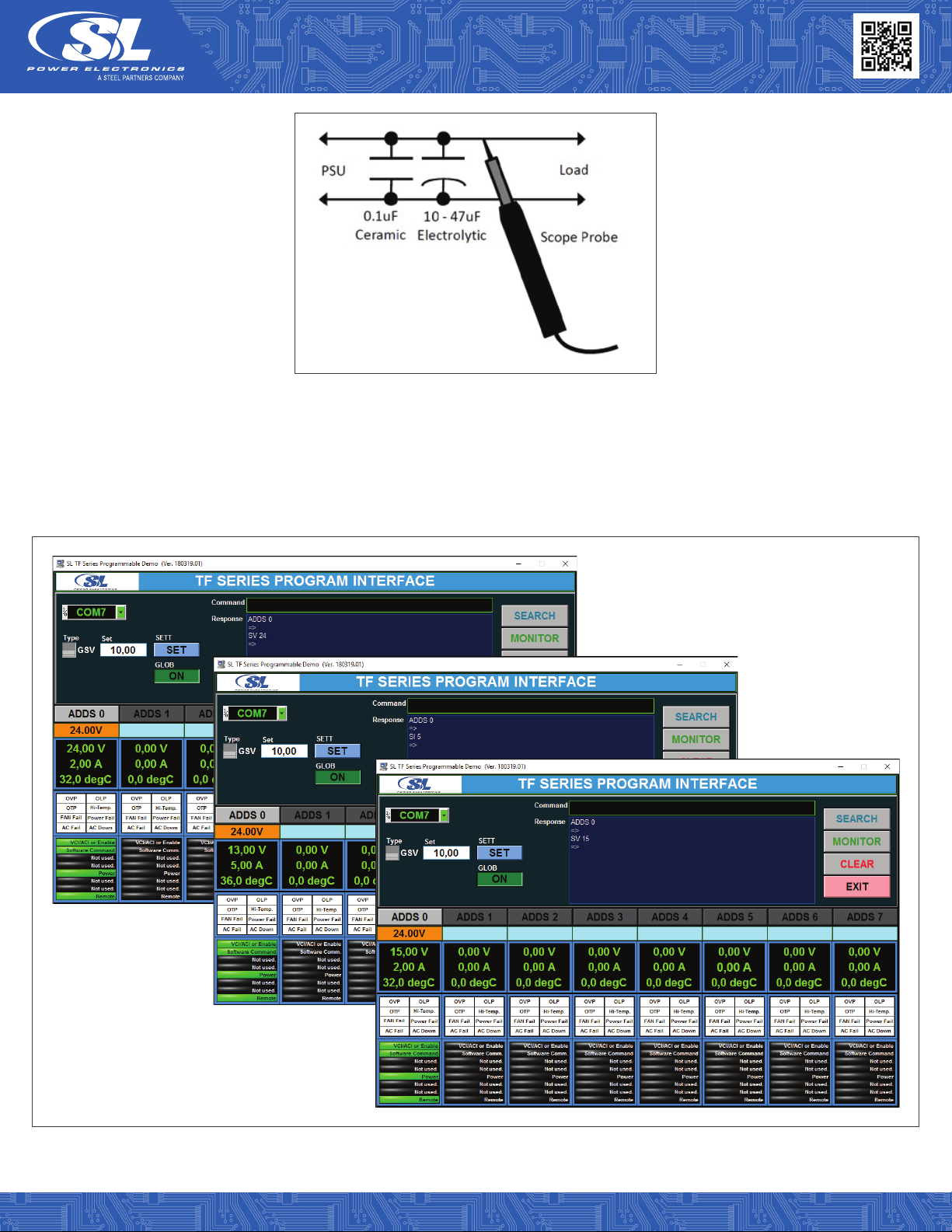
Output Ripple Measurement Method
• Output noise and ripple limits are defined in the product datasheet and may vary depending on the output voltage. Consult the
product datasheet prior to assessing the output ripple and noise measurement results.
• Noise measurements are made with noise probe directly at the end of 1.8m twisted pair wires terminated with a 0.1uF ceramic and
10uF electrolytic low ESR capacitors. Use a short tip oscilloscope voltage probe when making the measurement. This is required
to eliminate measurement error due to impedance imbalance errors introduced by the scope probe ground lead length.
Industrial Power Supplies
Single Output 1500 Watt
TF1500 Family
TF1500 Application Note v1019 Copyright © 2019 SL Power Electronics Corp. All rights reserved. Page 5
Fig. 01: Noise measurement caps and probe diagram.
GUI Example
For the graphical user interface with the power supply a CT-251 module or similar can be used. Contact your local SLPE field applica-
tions support for GUI user manual and for more details.
Fig. 02: GUI Example.

Industrial Power Supplies
Single Output 1500 Watt
TF1500 Family
TF1500 Application Note v1019 Copyright © 2019 SL Power Electronics Corp. All rights reserved. Page 6
General Information and Precautions
• It is not recommended to connect TF series power supplies in series for higher output voltage. Contact your local application team
for higher voltage models.
• The TF series power supplies use 8-bit microcontroller. Therefore, the possible readout of output voltage and output current are
limited approximately to one decimal digit. For example, while reading with the tool the output voltage of 50.23V it will be reported
as 50.2V.
The feedback loop of TF series power supplies is implemented with 10-Bit A/D converters where 1-bit is reserved for factory parameter
adjustment. The remaining 9-bits are defining voltage and current resolution of the power supply. For easy calculation of minimum
output voltage or current steps use the following formula:
Calculation example for TF1500A24K (1500 Watt, 24V Model)

Industrial Power Supplies
Single Output 1500 Watt
TF1500 Family
TF1500 Application Note v1019 Copyright © 2019 SL Power Electronics Corp. All rights reserved. Page 7
PERFORMANCE DATA
The following data is provided to aid in proper selection and system design of TF1500A24K.
Additional performance data is available upon request.
Efficiency
Fig. 03: TF1500 series 24V model eciency @115VAC.
Fig. 04: TF1500 series 24V model eciency @230VAC.
Industrial Power Supplies
Single Output 1500 Watt
TF1500 Family
TF1500 Application Note v1019 Copyright © 2019 SL Power Electronics Corp. All rights reserved. Page 8
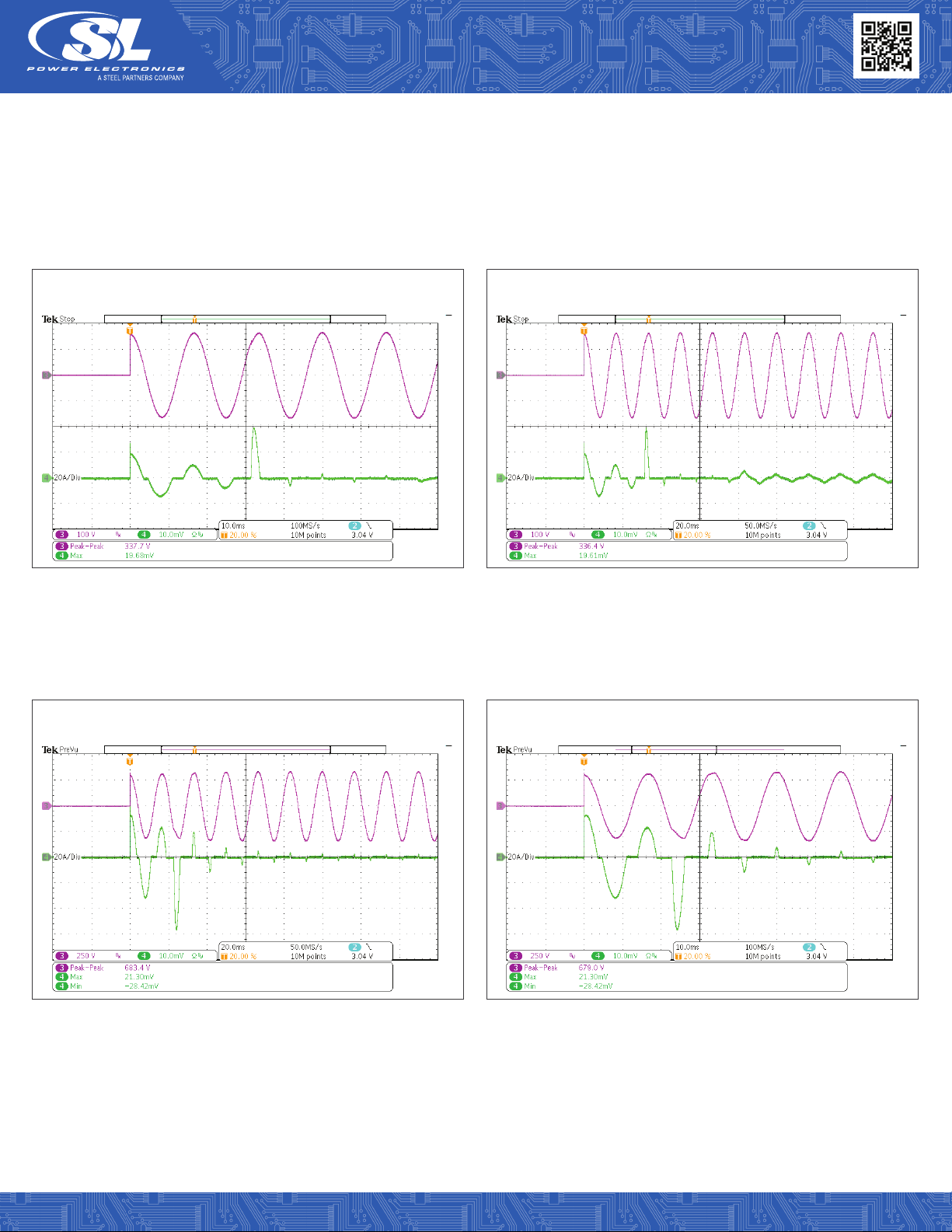
Fig. 05: INRUSH CURRENT AT 115VAC 100%.
Fig. 07: INRUSH CURRENT AT 230VAC 100%.
CH3: Input Voltage.
CH4: Output Current.
CH3: Input Voltage.
CH4: Output Current.
CH3: Input Voltage.
CH4: Output Current.
CH3: Input Voltage.
CH4: Output Current.
Fig. 06: INRUSH CURRENT AT 115VAC 100%.
Fig. 08: INRUSH CURRENT AT 230VAC 100%.
TF1500A24K01
TF1500A24K01
TF1500A24K01
TF1500A24K01
AC Inrush Current: 115VAC and 230VAC for 24V
The AC input inrush current (cold start power on) is shown in the oscillograms below. Select the correct circuit breakers to avoid
nuisance tripping while turning on one or more power supplies. On the input of each power supply EMI filtering X-Capacitors are used
for better EMC performance. During power-up of the unit these capacitors are been charged and so cause short current spikes. The
energy amount of this impulse is however very low and can be negligible.
Industrial Power Supplies
Single Output 1500 Watt
TF1500 Family
TF1500 Application Note v1019 Copyright © 2019 SL Power Electronics Corp. All rights reserved. Page 9
Fig. 09: TURN ON DELAY AT 115VAC 100%.
Fig. 11: TURN ON DELAY AT 230VAC 100%.
CH1: Output Voltage.
CH3: Input Voltage.
CH4: Output Current.
CH1: Output Voltage.
CH3: Input Voltage.
CH4: Output Current.
CH1: Output Voltage.
CH3: Input Voltage.
CH4: Output Current.
CH1: Output Voltage.
CH3: Input Voltage.
CH4: Output Current.
Fig. 10: TURN ON DELAY AT 115VAC 100%.
Fig. 12: TURN ON DELAY AT 230VAC 100%.
TF1500A24K01
TF1500A24K01
TF1500A24K01
TF1500A24K01
Turn-On Delay Time: 115VAC and 230VAC
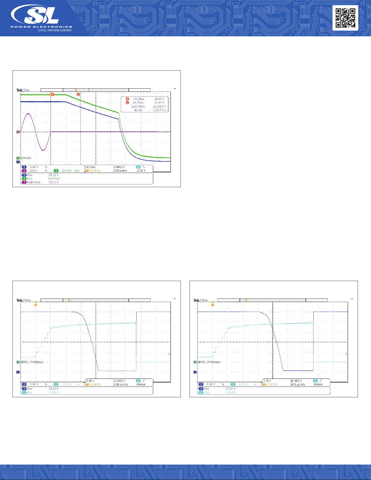
Constant Current Mode
At start-up a load current oscillation at near zero output voltage can occur. This anomaly is observed with electronic load operated in
constant current mode rising across very low voltage. The load is trying to get adjusted output current as soon as any voltage on out-
put of the power supply is present, ideally 100% of required current. Unlike a typical load the electronic loads are powered from external
power source which affect the load characteristic during turn-on and so create oscillation as seen below. This phenomenon is not seen
in constant resistance mode or in actualsystem loads where some voltage is developed before current starts toflow.

Industrial Power Supplies
Single Output 1500 Watt
TF1500 Family
TF1500 Application Note v1019 Copyright © 2019 SL Power Electronics Corp. All rights reserved. Page 10
Fig. 13: TURN ON RISE TIME AT 115VAC 100% CRM.
CH1: Output Voltage.
CH4: Output Current.
CH1: Output Voltage.
CH4: Output Current.
Fig. 14: TURN ON RISE TIME AT 230VAC 100 CRM.
TF1500A24K01 TF1500A24K01
Output Turn-On Rise Time: 115VAC and 230VAC No Load/Full Load
Constant Resistance Mode
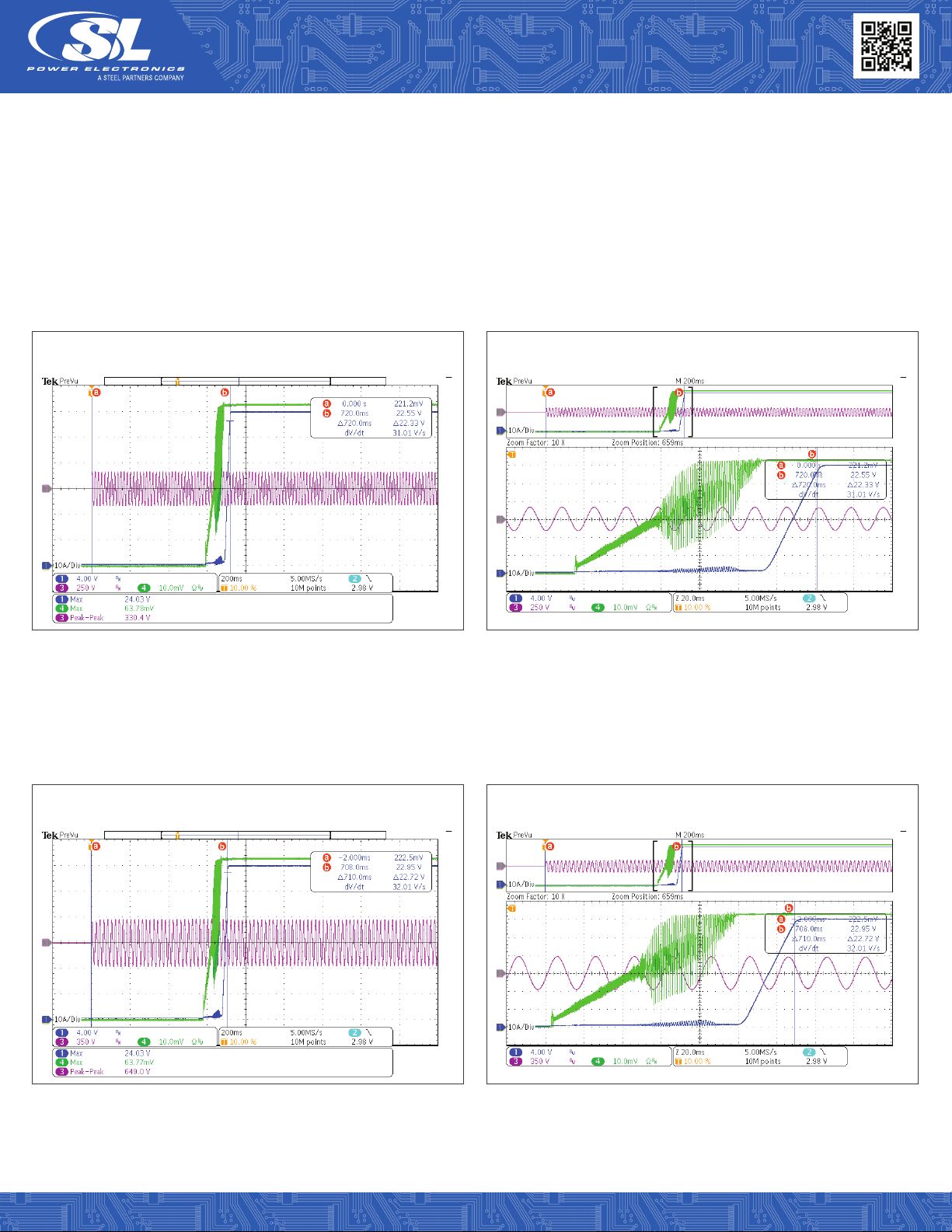
Fig. 15: HOLD-UP TIME AT 115VAC 100% CCM.
CH1: Output Voltage.
CH3: Input Voltage.
CH4: Output Current.
CH1: Output Voltage.
CH3: Input Voltage.
CH4: Output Current.
Fig. 16: HOLD-UP TIME AT 230VAC 100% CCM.
TF1500A24K01 TF1500A24K01
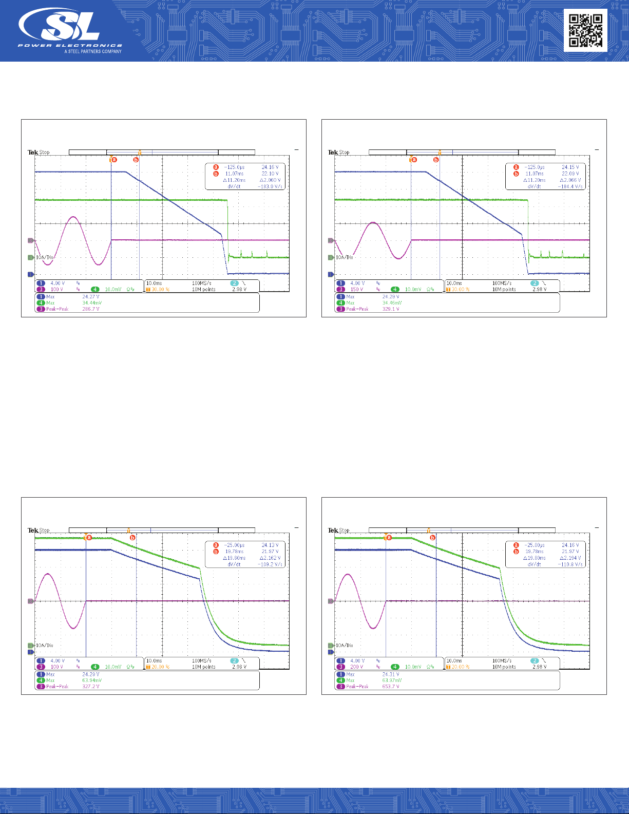
Output Hold-Up Time: 115VAC, 230VAC & 264VAC
Constant Current Mode (time to Vout drops to 90% rated)
Industrial Power Supplies
Single Output 1500 Watt
TF1500 Family
TF1500 Application Note v1019 Copyright © 2019 SL Power Electronics Corp. All rights reserved. Page 11
Fig. 15: HOLD-UP TIME AT 115VAC 100% CCM.
CH1: Output Voltage.
CH3: Input Voltage.
CH4: Output Current.
CH1: Output Voltage.
CH3: Input Voltage.
CH4: Output Current.
Fig. 16: HOLD-UP TIME AT 230VAC 100% CCM.
TF1500A24K01 TF1500A24K01
Output Hold-Up Time: 115VAC, 230VAC & 264VAC
Constant Current Mode (time to Vout drops to 90% rated)
Note: Load current oscillation during turn-off at near zero output voltage is an anomaly of the constant current electronic load during low voltage operation.
Fig. 18: HOLD-UP TIME AT 115VAC 100% CRM.
CH1: Output Voltage.
CH3: Input Voltage.
CH4: Output Current.
CH1: Output Voltage.
CH3: Input Voltage.
CH4: Output Current.
Fig. 19: HOLD-UP TIME AT 230VAC 100% CRM.
TF1500A24K01 TF1500A24K01
Output Hold-Up Time: 115VAC, 230VAC & 264VAC
Constant Resistance Mode (time to Vout drops to 90% rated)
Industrial Power Supplies
Single Output 1500 Watt
TF1500 Family
TF1500 Application Note v1019 Copyright © 2019 SL Power Electronics Corp. All rights reserved. Page 12
Fig. 20: HOLD-UP TIME AT 264VAC 100% CRM.
CH1: Output Voltage.
CH3: Input Voltage.
CH4: Output Current.
TF1500A24K01
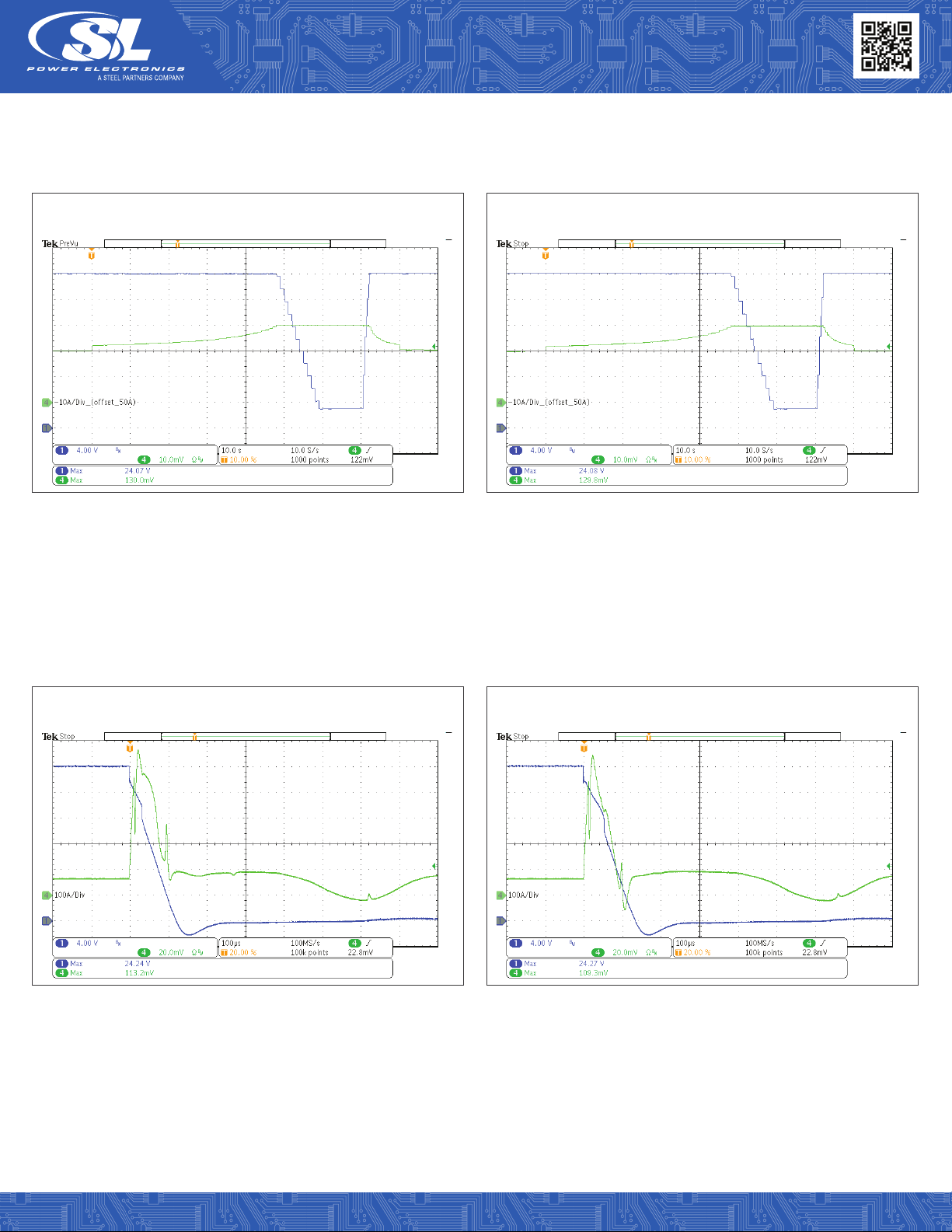
Fig. 21: OUTPUT OVERLOAD AT 115VAC CCM.
CH1: Output Voltage.
CH4: Output Current.
CH1: Output Voltage.
CH4: Output Current.
Fig. 22: OUTPUT OVERLOAD AT 230VAC CCM.
TF1500A24K01 TF1500A24K01
Overload Protection 115VAC and 230VAC
Constant Current Mode
For better visualization the power supply unit was preloaded with current of 62A.
Industrial Power Supplies
Single Output 1500 Watt
TF1500 Family
TF1500 Application Note v1019 Copyright © 2019 SL Power Electronics Corp. All rights reserved. Page 13
Fig. 23: SHORT CIRCUIT INITIAL EVENT AT 115VAC CRM.
CH1: Output Voltage.
CH4: Output Current.
CH1: Output Voltage.
CH4: Output Current.
Fig. 24: SHORT CIRCUIT INITIAL EVENT AT 230VAC CRM.
TF1500A24K01 TF1500A24K01
Constant Resistance Mode
Short-Circuit Protection 115VAC and 230VAC
Fig. 25: SHORT CIRCUIT INITIAL EVENT AT 115VAC 100%.
CH1: Output Voltage.
CH4: Output Current.
CH1: Output Voltage.
CH4: Output Current.
Fig. 26: SHORT CIRCUIT INITIAL EVENT AT 230VAC 100%.
TF1500A24K01 TF1500A24K01

Industrial Power Supplies
Single Output 1500 Watt
TF1500 Family
TF1500 Application Note v1019 Copyright © 2019 SL Power Electronics Corp. All rights reserved. Page 14
Fig. 27: SHORT CIRCUIT NO HCC-UP 115VAC 100%.
CH1: Output Voltage.
CH4: Output Current.
CH1: Output Voltage.
CH4: Output Current.
Fig. 28: SHORT CIRCUIT NO HCC-UP 230VAC 100%
TF1500A24K01 TF1500A24K01
Fig. 29: SHORT RECOVERY 115VAC 100%.
CH1: Output Voltage.
CH4: Output Current.
CH1: Output Voltage.
CH4: Output Current.
Fig. 30: SHORT RECOVERY 230VAC 100%.
TF1500A24K01 TF1500A24K01

Industrial Power Supplies
Single Output 1500 Watt
TF1500 Family
TF1500 Application Note v1019 Copyright © 2019 SL Power Electronics Corp. All rights reserved. Page 15
Full Cycle
Fig. 33: TRANSIENT RESPONSE AT 115VAC, 10%-50% STEP LOAD.
Fig. 35: TRANSIENT RESPONSE AT 115VAC, 10%-50% STEP LOAD.
Fig. 34: TRANSIENT RESPONSE AT 230VAC, 10%-50% STEP LOAD.
Fig. 36: TRANSIENT RESPONSE AT 230VAC, 10%-50% STEP LOAD.
Transient Response 10%-50% 115VAC and 230VAC
Fig. 31: TRANSIENT RESPONSE AT 115VAC, 10%-50% STEP LOAD.
CH1: Output Voltage.
CH4: Output Current.
CH1: Output Voltage.
CH4: Output Current.
Fig. 32: TRANSIENT RESPONSE AT 230VAC, 10%-50% STEP LOAD.
TF1500A24K01 TF1500A24K01

Industrial Power Supplies
Single Output 1500 Watt
TF1500 Family
TF1500 Application Note v1019 Copyright © 2019 SL Power Electronics Corp. All rights reserved. Page 16
Transient Response 50%-100% 115VAC and 230VAC
Full Cycle
Fig. 37: TRANSIENT RESPONSE AT 115VAC, 50%-100% STEP LOAD.
Fig. 39: TRANSIENT RESPONSE AT 115VAC, 50%-100% STEP LOAD.
Fig. 41: TRANSIENT RESPONSE AT 115VAC, 50%-100% STEP LOAD.
CH1: Output Voltage.
CH4: Output Current.
CH1: Output Voltage.
CH4: Output Current.
Fig. 38: TRANSIENT RESPONSE AT 230VAC, 50%-100% STEP LOAD.
Fig. 40: TRANSIENT RESPONSE AT 230VAC, 50%-100% STEP LOAD.
Fig. 42: TRANSIENT RESPONSE AT 230VAC, 50%-100% STEP LOAD.
TF1500A24K01 TF1500A24K01
Industrial Power Supplies
Single Output 1500 Watt
TF1500 Family
TF1500 Application Note v1019 Copyright © 2019 SL Power Electronics Corp. All rights reserved. Page 17
Fig. 43: LOCAL CURRENT PROGRAM (ACI) 115VAC.
CH1: Output Voltage.
CH2: Current Program (ACI).
CH4: Output Load Current (Aout) 1.5KW/62.5A (10A/Div).
Input Voltage: 115VAC.
CH1: Output Voltage.
CH2: Current Program (ACI).
CH4: Output Load Current (Aout) 1.5KW/62.5A (10A/Div).
Input Voltage: 230VAC.
Fig. 44: LOCAL CURRENT PROGRAM (ACI) 230VAC.
TF1500A24K01 TF1500A24K01
SIGNAL WAVEFORMS
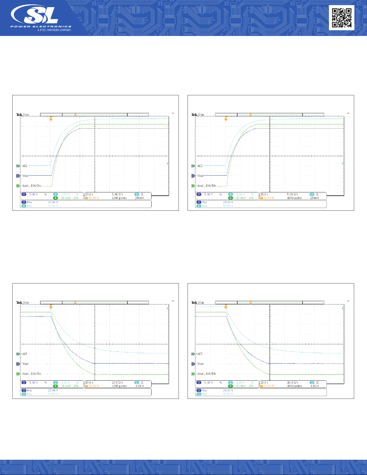
Local Current Program (ACI) 115VAC and 230VAC
The Local Mode Current Program (ACI) signal was monotonically controlled using an external DC source. This external source was
remotely voltage controlled by charging RC circuit (4.7mF & 6.2K). This (ACI) signal programs the current limit at a desired level by
tuning the ACI signal voltage to the desired level.
Constant Current Mode
On the Constant Current Mode (CCM) scope plots, the UUT output is loaded at 1.5KW/62.5A. It shows how the load current follows the
ACI signal and that the output voltage only comes up when the ACI signal has reached a programable level for a current limit above the
load current level being applied to the UUT.

Industrial Power Supplies
Single Output 1500 Watt
TF1500 Family
TF1500 Application Note v1019 Copyright © 2019 SL Power Electronics Corp. All rights reserved. Page 18
Fig. 45: LOCAL CURRENT PROGRAM (ACI) 115VAC.
CH1: Output Voltage.
CH2: Current Program (ACI).
CH4: Output Load Current (Aout) 1.5KW/62.5A (10A/Div).
Input Voltage: 115VAC.
CH1: Output Voltage.
CH2: Current Program (ACI).
CH4: Output Load Current (Aout) 1.5KW/62.5A (10A/Div).
Input Voltage: 230VAC.
Fig. 46: LOCAL CURRENT PROGRAM (ACI) 230VAC.
TF1500A24K01 TF1500A24K01
Industrial Power Supplies
Single Output 1500 Watt
TF1500 Family
TF1500 Application Note v1019 Copyright © 2019 SL Power Electronics Corp. All rights reserved. Page 19
Fig. 47: LOCAL CURRENT PROGRAM (ACI) 115VAC.
CH1: Output Voltage.
CH2: Current Program (ACI).
CH4: Output Load Current (Aout) 1.5KW/62.5A (10A/Div).
Input Voltage: 115VAC.
CH1: Output Voltage.
CH2: Current Program (ACI).
CH4: Output Load Current (Aout) 1.5KW/62.5A (10A/Div).
Input Voltage: 230VAC.
Fig. 48: LOCAL CURRENT PROGRAM (ACI) 230VAC.
TF1500A24K01 TF1500A24K01
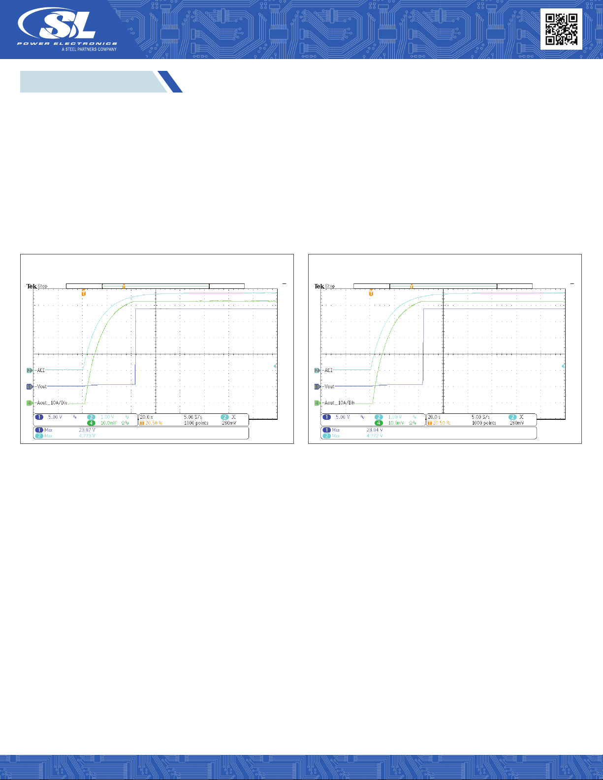
Constant Resistance Mode
On the Constant Resistance Mode scope plots, the UUT output is loaded with fixed resistance. It also shows how the load current fol-
lows the ACI signal and that the output voltage follows the load current all the way to when the ACI signal has reached the programable
level for a current limit above the load resistance level being applied to the UUT.
Fig. 49: LOCAL CURRENT PROGRAM (ACI) 115VAC.
CH1: Output Voltage.
CH2: Current Program (ACI).
CH4: Output Load Current (Aout) 1.5KW/62.5A (10A/Div).
Input Voltage: 115VAC.
CH1: Output Voltage.
CH2: Current Program (ACI).
CH4: Output Load Current (Aout) 1.5KW/62.5A (10A/Div).
Input Voltage: 230VAC.
Fig. 50: LOCAL CURRENT PROGRAM (ACI) 230VAC.
TF1500A24K01 TF1500A24K01
Industrial Power Supplies
Single Output 1500 Watt
TF1500 Family
TF1500 Application Note v1019 Copyright © 2019 SL Power Electronics Corp. All rights reserved. Page 20
Fig. 51: LOCAL VOLTS PROGRAM (ACI) 115VAC.
CH1: Output Voltage.
CH2: Voltage Program (ACI).
CH4: Output Load Current (Aout) 1.5KW/62.5A (20A/Div).
Input Voltage: 115VAC.
CH1: Output Voltage.
CH2: Voltage Program (ACI).
CH4: Output Load Current (Aout) 1.5KW/62.5A (20A/Div).
Input Voltage: 230VAC.
Fig. 52: LOCAL VOLTS PROGRAM (ACI) 230VAC.
TF1500A24K01 TF1500A24K01
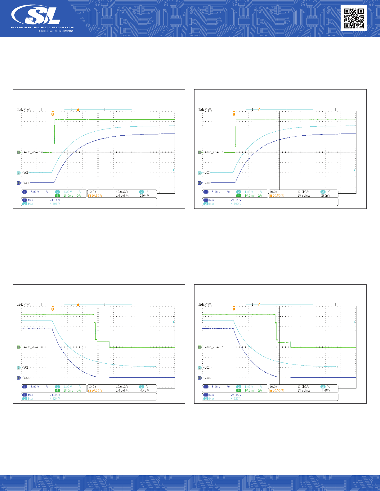
Local Mode Voltage Programing (VCI) 115VAC and 230VAC
The Local Mode Voltage Program (VCI) signal was monotonically controlled using an external DC source.
This external source was remotely voltage controlled by charging RC circuit (4.7mF & 6.2K).
Fig. 53: LOCAL VOLTS PROGRAM (ACI) 115VAC.
CH1: Output Voltage.
CH2: Voltage Program (ACI).
CH4: Output Load Current (Aout) 1.5KW/62.5A (20A/Div).
Input Voltage: 115VAC.
CH1: Output Voltage.
CH2: Voltage Program (ACI).
CH4: Output Load Current (Aout) 1.5KW/62.5A (20A/Div).
Input Voltage: 230VAC.
Fig. 54: LOCAL VOLTS PROGRAM (ACI) 230VAC.
TF1500A24K01 TF1500A24K01
Table of contents
Other SL Power Supply manuals


