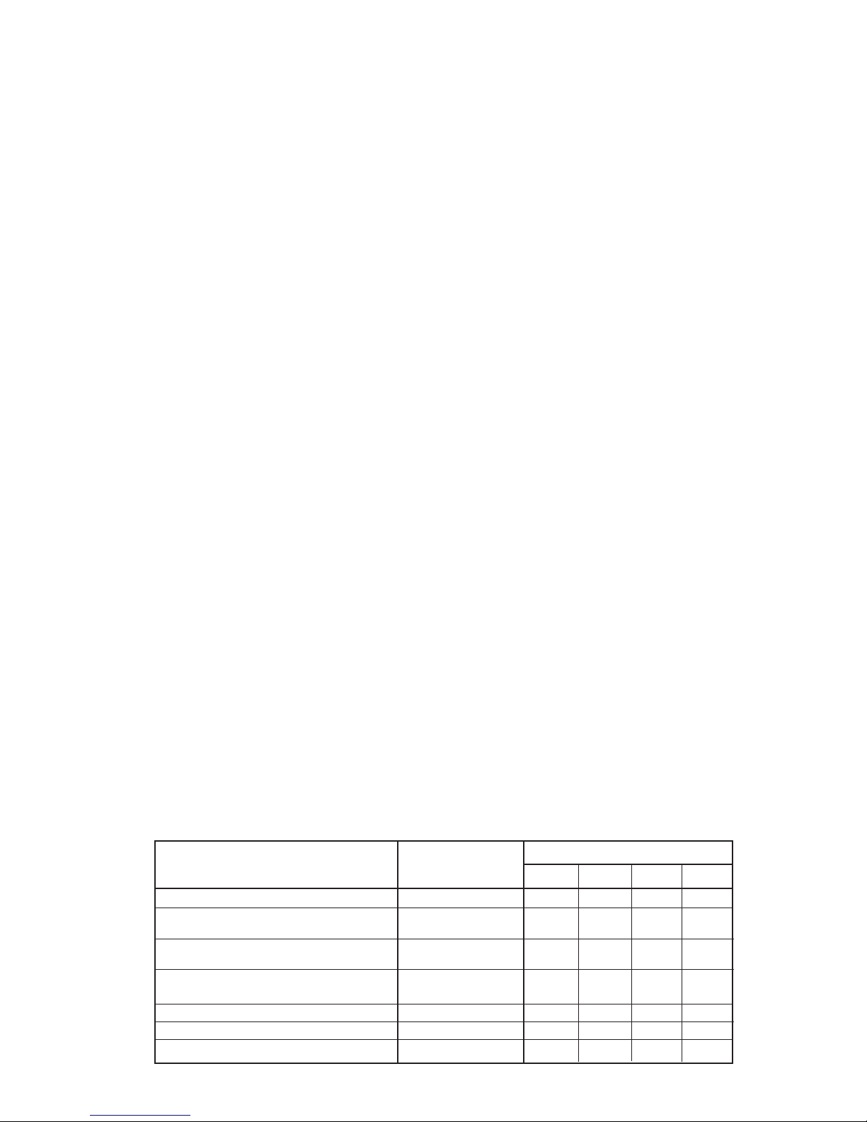
Used on heater model
Description Part Number WH-30 WH-40* WH-60* WH-80*
Temperature control -Honeywell 4080B-1295 664131000 X X X X
Temperature and pressure relief
valve - Watts 100 XL-8 664121000 X X X
Temperature and pressure relief
valve - Watts 40 XL-8 664122000 X
Trenton inverted nipple
3/4”MPT x 3/4”FPT x 21/2”long -brass 664129000 X
3/4” NPT brass tee 664126000 X X
1” NPT brass tee 664127000 X
3/4” NPT x 1” NPT reducer bushing - brass 664128000 X
REPLACEMENT PARTS LIST
OPERATING PROCEDURES
1. Filling the heater tank
a) Make sure all drain valves on the cold or hot water supply
piping are closed.
b) Open the nearest hot water faucet and any shutoff valves
on the domestic hot water supply piping from the tank out-
let.
c) Open the shutoff valve on the cold water supply piping to
the tank inlet.
d) Allow the cold water supply to fill the tank by leaving the hot
water faucet open until all air is purged from the tank and
piping, and a steady flow of water is observed from the
faucet.
e) Close the hot water faucet, but leave all piping shutoff
valves open.
f) Any other hot water faucets fed by this heater may be
opened to purge air from their supply piping, and then shut
off after a steady flow of water is observed from the faucet.
2. Filling the heater coil
a) Attach a hose to the drain valve on the coil outlet (return to
boiler). Place the end of the hose into a drain or bucket in a
manner that will prevent potentially hot water from spraying
on any persons in the area.
b) If a shutoff valve has been installed between the drain valve
and the boiler return, keep this valve shut at this time.
c) Open the shutoff valve (and on a zone valve system, man-
ually open zone valve) on the supply piping from the boiler.
d) Open the drain valve on the coil outlet to purge the air from
the coil. When a steady flow of water is observed from the
drain, then open the shutoff valve on the return piping to the
boiler. Additional air from the return piping should purge
itself at this time. Close the drain valve when the steady flow
of water is again observed.
e) Remove the hose from the drain valve. Leave the drain
valve closed. Leave all shutoff valves open. Return zone
valve to automatic operation.
f) Purge air from remaining zones, if necessary. Check boiler
gauge pressure reading afterward to be appropriate. 15 psi
is normal for most installations.
3. Operating the heater
a) After the system has been manually purged of its air, and
all components (valves, vents, controllers) have been set
properly, the boiler can be started. NEVER operate this
heater until this has been done.
b) The maximum setting for the boiler water supply to the
heater coil is 220° F.
c) The maximum setting for the heater tank temperature con-
trol is 160° F. Unless there is specific demand for very high
temperature domestic hot water, the control setting should
be set at the lower end of the temperature range of adjust-
ment to reduce the risk of scalding injury. Some areas
require that the tank control setting be below 130°.
d) When the temperature of the water in the heater tank is
below the setting on the tank control, the boiler and circu-
lator should start. If a zone valve is used for this zone, it
should open at this time. When the temperature of the
water in the heater tank reaches the temperature setting on
the tank control, the boiler and circulator should turn off
(and zone valve, if used, should close). If other zones for
heating are in demand, this would also run boiler and cir-
culator(s). Cycling of the boiler on high limit is not abnor-
mal, particularly if only one zone is in demand. On initial
startup with a cold tank, a considerable amount of time may
be required for the tank to reach desired temperature.
Maintenance recommendations:
1. Temperature and pressure relief valve operation check
a) Once a year, the T & P valve must be manually operated to
ensure safe and proper operation.
b) Make sure that the discharge line from the T & P valve is
directed towards a drain or some collection method, and
will not spray onto any person.
c) Use lever on T & P valve to open. A steady discharge of hot
water should be noticed. After releasing this lever, the
T & P valve should close and fully shut off this flow.
d) If the T & P valve does not function properly, it must be
replaced with the same model or its equivalent. DO NOT
plug the outlet of this valve if a dripping condition occurs.
2. Flushing the heater tank
a) Once a year, or if a persistent discolored water condition
exists, the heater tank should be manually flushed to
remove possible sediment accumulation.
b) Turn off the boiler before draining the heater tank.
c) Attach a hose to the drain valve on the cold water supply to
the tank. Place the end of the hose into a drain or bucket in
a manner that will prevent potentially hot water from spray-
ing on any persons in the area.
d) Close the shutoff valve on the cold water supply to the tank.
e) Open the drain valve on the cold water supply and drain
down tank completely. Open the T & P valve or a nearby
faucet to break vacuum on drain.
f) After the heater tank is drained, close the drain valve and
reopen the cold water supply valve to refill the tank. The
introduction of water into the tank should act to stir up sed-
iment accumulations which can then be drained through
the drain valve. Go back through the draining and filling
process until clean water is observed passing out the drain.
g) Once clear water conditions are accomplished, make sure
the heater tank and all domestic hot water supply piping is
purged of air and discolored water. Leave the drain closed,
check for the T & P valve to be properly seated, and make
sure all shutoff valves for the hot and cold water supply are
left open. The boiler can then be returned to operation.
7
*Also applies to double wall coil models WH-40 D, WH-60 D and WH-80 D.


 Operation and maintenance instructions")