SLAT Safe DC SDC-M User manual
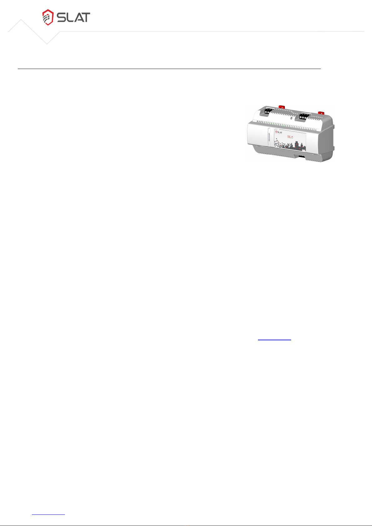
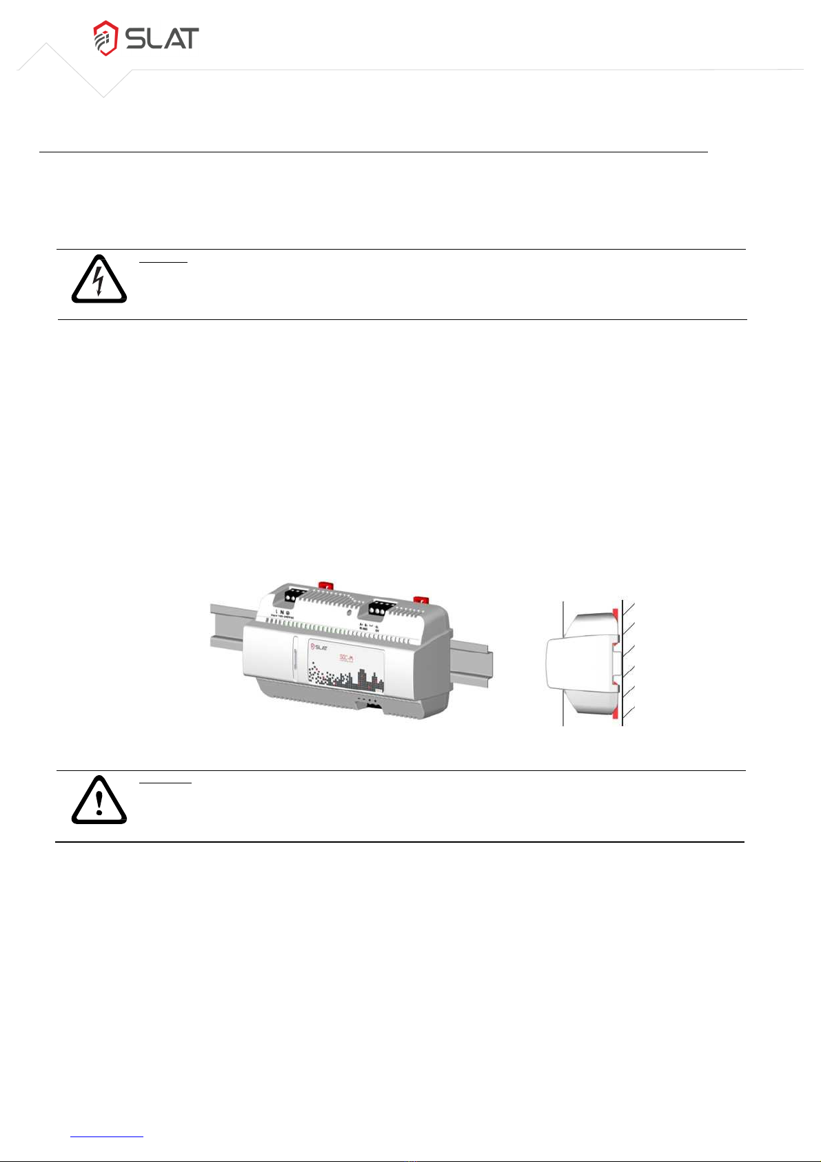
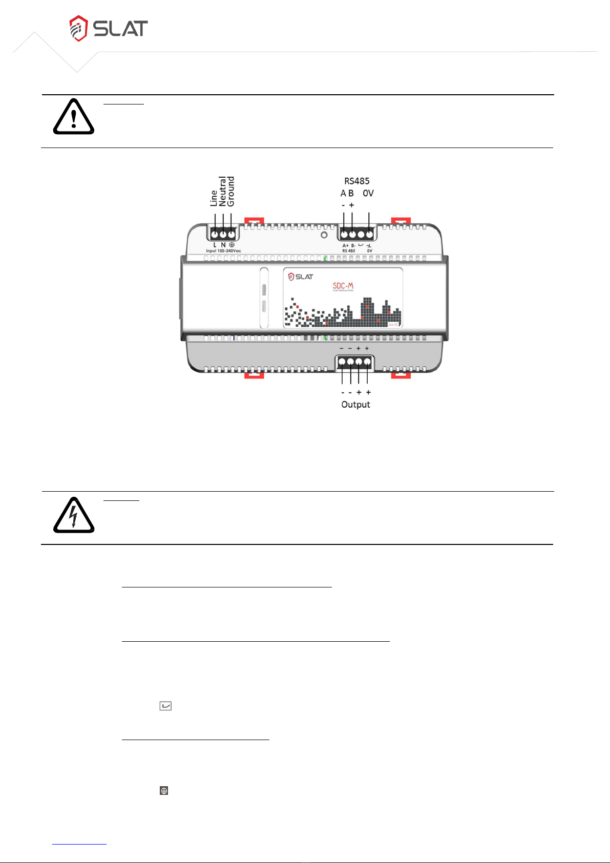
Safe DC SDC
-
M
Micro-UPS DC
SDC
-
M
12
V
-
15
V
-
24
V
DMR
RS
Modbus / BACnet MS/TP
EN perating Instructions
MAN160006 | Aa | 2016
.10


MAN160006 | Aa | 2016.10
SLAT perating instructions ©2016 SLAT
Subject to change
www.slat.com 1
1.
Safety 3
2.
Directives and environment and public health protection 4
3.
General Information 5
3.1 The company 5
3.2 Purpose of the document 5
3.3 Related documentation 5
3.4 Intended audience 5
3.5 Indicator labels 6
4.
The product
4.1 Description 7
4.2 perating principle 7
4.3 Schematic diagram 8
4.4 Product view 8
4.5 Available references 9
4.6 Scope of delivery 9
4.7 Associated products 9
5.
Energy storage 10
5.1 Available storage option 10
5.2 Technology 10
5.3 Autonomy curves 11
5.4 Autonomy duration 11
5.5 Self-discharge 11
6.
Installation 12
6.1 Positioning / Installation on support 12
6.2 Connection 13
Connection specifications 13
Wiring 13
.
Commissioning 16
7.1 First configuration 16
7.2 Subsequent configurations 17
8.
Operation 18
8.1 Local report on product 18
8.2 Remote report 18
Alarm reports 18
Communication 19
9.
Maintenance and troubleshooting 26

MAN160006 | Aa | 2016.10
SLAT perating instructions ©2016 SLAT
Subject to change
www.slat.com 2
10.
Technical data 28
10.1 Electrical characteristics 28
Electric power supply characteristics 28
Electrical output characteristics 30
Functional characteristics 31
Peak current 31
10.2 Mechanical characteristics 32
10.3 Environmental specifications 32
10.4 Standards 33
Safety standards 33
EMC standards 33
11.
Warranty and Product Returns 34
11.1 Warranty 34
11.2 Product Returns 34
Product under warranty 34
Product not under warranty 35

MAN160006 | Aa | 2016.10
SLAT perating instructions ©2016 SLAT
Subject to change
www.slat.com 3
1. Safety
These operating instructions contain all the instructions to follow in order to install, commission and operate the
SDC-M Uninterruptible Power Supply. It is recommended to follow them very carefully to ensure an optimum
functioning of the product.
It is vital to read the Safety Precautions before installing or operating this product.
Safety Precautions:
SDC-M is a Micro-UPS DC designed to be connected to the public 100 V / 240 V mains network. It must not be
installed outdoors. It ensures continuity of service for equipment in case of power failure. The lithium - ion backup
function is integrated into the product.
• An easily accessible two-pole circuit-breaker must be provided upstream.
• To avoid any risk of electric shock, all INTERVENTIONS must be carried out with the equipment
SWITCHED O (upstream two-pole circuit-breaker open).
• Interventions with the equipment switched on are authorized only when it is impossible to switch the
equipment off. The operation must only be performed by qualified personnel.
• During installation, connect the ground wire first and disconnect it last when dismantling.
• The equipment is only designed to be used in an enclosure with restricted access (IP30 control cabinet),
and to be installed on a concrete surface or any other non-combustible surface.
• The product can be installed horizontally or vertically.
• Sufficient convection must be guaranteed (minimum top and bottom clearance space 30 mm).
• The wires must be dimensioned and protected according to the maximum input/output current.
• bserve the thermal and mechanical limits.
• For prolonged storage or disconnection, press the stop button back-up function. (see on Figure 4.2 in
chapter 4.4: Disconnect backup push-button)
• The backup is maintenance-free. Do not open it.

MAN160006 | Aa | 2016.10
SLAT perating instructions ©2016 SLAT
Subject to change
www.slat.com 4
2. Directives and environment and public health protection
The SLAT company and its product comply with directives and are committed to protecting the environment and
public health.
SLAT manufactures all its products in accordance with RoHS and WEEE environmental directives.
SLAT products are qualified by CE. The CE mark dates back to 2011.

MAN160006 | Aa | 2016.10
SLAT perating instructions ©2016 SLAT
Subject to change
www.slat.com 5
3. General Information
3.1 The company
To meet its customers' requirements more effectively:
• SLAT has been designing and manufacturing all its products in accordance with the IS 14001 standard
since 2007.
• SLAT recycles its products at the end of their life cycle, by means of its recycling program. (For end-of-
life recycling, the backup can easily be removed by qualified professionals independent from SLAT.)
3.2 Purpose of the document
The operating instructions provide the information necessary for the positioning, the connection, the
configuration and the operation of the SDC-M equipment.
Theses instructions are also available in PDF format in the Library Account at www.slat.com .
3.3 Related documentation
The following documents are associated with these operating instructions:
• Installation manual
• Commercial brochure
• Datasheet
This documentation is available at www.slat.com.
3.4 Intended audience
The operations described in this document should be performed only by authorized trained staff.

MAN160006 | Aa | 2016.10
SLAT perating instructions ©2016 SLAT
Subject to change
www.slat.com 6
3.5 Indicator labels
This document comprises three types of important notices.
The type of notice informs you of the potential consequences in the case of non-compliance with the instructions.
These consequences are not exhaustive and are sorted in order of ascending risk:
IMPORTANT REMARK
!
Contains additional information. Non-compliance will not cause damage to equipment or personal injuries.
CAUTION!
Equipment and goods can be seriously damaged or people seriously injured if the precautions for use are not
followed.
DANGER!
Non-compliance may result in serious injury or death.

MAN160006 | Aa | 2016.10
SLAT perating instructions ©2016 SLAT
Subject to change
www.slat.com 7
4. The product
4.1 Description
Micro-UPS with lead and cadmium-free "Smart Backup Inside" with
very long service life.
SDC-M are communicating Micro UPS (Uninterruptible Power Supply) of the
Safe DC range dedicated to Smart Building applications. They ensure the
continuity of service of the equipment they supply and maintain
communication with the supervisor in the event of a power failure.
Main functions
• Keeps control of the Smart Building in case of a power failure or glitch.
• Filters electromagnetic disturbances.
• Avoids the reporting of false alarms to the supervisor due to network glitches.
• Delivers a constant voltage to equipment.
Built-in functions
• perates in power-saving mode when the backup is charged.
• Micro stealth mode with controllable operational maintenance.
• Indicates the % of remaining autonomy.
• 2 SDC-M can be configured in parallel without accessories for an increase in power, to increase the
backup duration or a 100% redundancy.
• Provides selectivity of electrical protections of the equipment.
Benefits of the SDC-M range
• Ultra-compact / Plug and Play, parallel configuration without accessories.
• Performs self-diagnostic and that of its environment.
• Choice of configuration in either Modbus or BACnet MS/TP via the website www.slat.com.
• Lead-free, cadmium-free backup, 100% recyclable.
• Service life of more than 10 years.
4.2 Operating principle
When the network is operating, the emergency power supply SDC-M stores energy and continuously powers the
load.
When the mains fail, the built-in emergency supply continues to provide power to the load.
in the event of a complete discharge, the recharging time to 100% of the backup will in all cases be less than 20
hours of mains presence.

MAN160006 | Aa | 2016.10
SLAT perating instructions ©2016 SLAT
Subject to change
www.slat.com 8
4.3 Schematic diagram
The visual below shows the product diagram when installed:
Figure 4.1: Schematic diagram
4.4 Product view
Figure 4.2: Product view
Name Use
A Mains input Mains input
B Disconnect backup push button The push button is used to switch off the power supply once the
mains power is cut.
C RS485 communication + alarm
report
Communication uses an RS485 serial connection and the Modbus
or BACnet MS/TP protocol to retrieve detailed product
information (see chapter 8.2.2).
The alarm report output is an open collector dry contact that
indicates whether there is a fault on the product (see chapter
8.2.1).
D Status light (LED) The light indicates the product status (see chapter 8.1).
E utputs User voltage outputs
F Clip Attachment to clip the box to the DIN rail or to fix it on a
mounting plate (depending on the clip’s position)
G Rail attachment Attachment to fix the box to the DIN rail.
Table 4.1: Elements on the product faces
AC
DC
DC
DC
Mains RS485
utput

MAN160006 | Aa | 2016.10
SLAT perating instructions ©2016 SLAT
Subject to change
www.slat.com 9
4.5 Available references
The list of available product references is to be found at www.slat.com.
The references are designed as follows:
SDC-
M 12V
2 D DMR
RS
① ②
③
④
⑤
⑥ ⑦
Meaning
1 Range name
2 Application type
3 utput voltage [12 V / 15 V / 24 V DC]
4 Power range [2 → 30 W]
5 Backup type [D] (see Table 5.1)
6 Box type
7 Type of communication port
Table 4.2: eaning of the references
4.6 Scope of delivery
The product is delivered with its installation manual.
4.7 Associated products
A setup cable is available with the following reference: A SETUP KIT SA E DC RS

MAN160006 | Aa | 2016.10
SLAT perating instructions ©2016 SLAT
Subject to change
www.slat.com 10
5. Energy storage
5.1 Available storage option
SLAT products are combined with batteries or backup systems. They are used as emergency supplies in the event
the mains voltage disappears. The available autonomy then depends on the capacity of the built-in backup.
In the SDC-M the backup system is already built-in (Smart Backup Inside). For the DMR version of the SDC-M, one
backup pack is available:
Backup D
20 Wh
Table 5.1: Backup option
5.2 Technology
The technology behind the SDC-M backup is Lithium-Iron-Phosphate (LiFeP
4
). LiFeP
4
has the best safety
characteristics of any Lithium storage system (see Figure 5.1). This includes better resistance to impacts and
extreme temperatures.
Figure 5.1: LiFePO
4
characteristics
All SDC-M backups have the following characteristics:
• Lithium-Iron-Phosphate technology (LiFeP
4
)
• No risk of thermal runaway
• Storage: 9 months without recharging
• 10 year service life @ 25°C
• Lead-free, cadmium-free, 100% recyclable

MAN160006 | Aa | 2016.10
SLAT perating instructions ©2016 SLAT
Subject to change
www.slat.com 11
5.3 Autonomy curves
Figure 5.2: Autonomy curves
5.4 Autonomy duration
Backup D
Operating power Autonomy expressed in hours and minutes
5 W 3h23
7 W 2h32
10 W 1h48
15 W 1h13
20 W 0h55
25 W 0h44
30 W 0h36
Table 5.2: Autonomy vs Power vs used Backup
5.5 Self-discharge
The self-discharge current for the SDC-M is 70 mA.

MAN160006 | Aa | 2016.10
SLAT perating instructions ©2016 SLAT
Subject to change
www.slat.com 12
6. Installation
6.1 Positioning / Installation on support
The product must be installed according to the EN 60950 standards.
DANGER!
This product must be installed in a control cabinet meeting the requirements of the IP30 standards.
Assembly instructions
The DMR box of the SDC-M is designed to be fixed to a DIN rail or to a mounting plate in a control cabinet:
1. DIN rail
a. pen the two lower mounting clips (red parts) by pushing them outwards with the help of a flat-
head screwdriver.
b. Position the top part of the attachment (on the rear of the product) on the top part of the rail,
tilting the product backwards. Make sure the two upper mounting clips are placed behind the rail.
c. Place the product in a straight position on the DIN rail and close the lower clips, opened in section
(a.), again.
d. The product should hold itself. Figure 6.1 shows how the box must be positioned on the DIN rail
once assembled.
Figure 6.1: Position on DIN rail
CAUTION
!
To prevent the product from falling, make sure it is securely attached to the bottom and top of the rail!
2. Mounting plate
a. pen the four mounting clips (red parts) by pushing them outwards with the help of a flat-head
screwdriver so that they are in the position shown in Figure 6.2.
b. Attach the product in the way indicated in Figure 6.2 using four screws.

MAN160006 | Aa | 2016.10
SLAT perating instructions ©2016 SLAT
Subject to change
www.slat.com 13
Figure 6.2: Position on mounting plate
6.2 Connection
Connection specifications
Mains 0.75 mm² … 2.5 mm²
User output 0.75 mm² … 2.5 mm²
Communication/ alarm report 0.2 mm² … 2.5 mm²
Length to be stripped 7 mm
Tightening torque 0.5 Nm … 0.6 Nm
Connections Screw terminals
Table 6.1: Connection specifications
DANG
ER!
The wire sectional area must be chosen according to the operating current.
Wiring
After installing the product on its support, the wiring must be carried out. In this way the emergency power supply
(the product) is connected with the application, the control point and the mains.
Symbols have been placed on the product (above or below the screw terminals) to indicate the name of the signal
/ wire so as to facilitate connection (see also Figure 6.3)
Wiring methods
All the wires are attached to the product using a screw terminal (the three black parts on Figure 6.3). They have
to be connected according to the symbols indicated on the product, using a regular screwdriver
CAUTION!
To avoid breaking the screw terminal, comply with the screw tightening torque indicated in Table 6.1.

MAN160006 | Aa | 2016.10
SLAT perating instructions ©2016 SLAT
Subject to change
www.slat.com 14
CAUTION!
To avoid wiring mistakes, make a careful note of the positioning of the screw terminals and their respective
symbols.
Figure 6.3: Wiring
Connection
DANGER!
To connect the wires, the application must be switched off. The upstream circuit-breaker of the application
must be open!
The wires are connected according to the following steps:
1. Connect the emergency power supply to the application
The product is connected to the application by the four-point screw terminal located on the bottom right.
The initial output voltage is set to the rated value.
2. Connect the RS485 communication cable and the alarm report contacts
The four-point screw terminal located on the top right provides the connection to an external PLC or
computer.
• To allow RS485 communication the wires must be connected to the A, B and 0V contacts.
• To connect the alarm report, the wire must be connected to the 3
rd
contact (with the switch symbol
).
3. Connect the power supply to the mains
Below the three-point screw terminal (top left), the type of wire is indicated by 3 symbols:
• L Line wire
• N Neutral wire
• Ground wire

MAN160006 | Aa | 2016.10
SLAT perating instructions ©2016 SLAT
Subject to change
www.slat.com 15
DANGER!
Before connecting the power supply to the mains, the ground wire must be connected!
After connecting the ground wire, the neutral and line wires can be connected.
nce the connections have been made, the upstream circuit-breaker can be closed. To complete the installation,
the LED status must be verified to be green.

MAN160006 | Aa | 2016.10
SLAT perating instructions ©2016 SLAT
Subject to change
www.slat.com 16
7. Commissioning
Before starting to commission the power supply, check that the LED is green. This means the product is connected
properly and ready to function.
Software configuration
The basic communication protocol is Modbus It can be configured in BACnet MS/TP using the configuration
software with the help of an optional setup cable (see chapter 4.7).
The communication parameters can be configured via the RS485 serial connection. SLAT provides a software that
allows simple configuration of these parameters. This software is available for download at www.slat.com .
The configuration software also makes it possible to choose to use the power supply in energy saving mode (EC )
and in stealth mode.
The EC Mode, once it is activated, allows the improvement of the power supply’s efficiency’s at low load (<20%
of I
max
) while ensuring an autonomy percentage. This one can be chosen during the configuration. The EC Mode
is factory set with a threshold of 80% of the available autonomy (see Figure 7.1).
The Stealth Mode allows the supervisor, using a Modbus or BACnet order, to disconnect the product to relieve
the mains. The product reconnects himself automatically once the remaining backup autonomy reaches the
guaranteed percentage chosen by the user during the configuration step.
7.1 irst configuration
Figure 7.1: Configurator
Figure 7.1 and the following paragraph explain how to set up the communication and the mode in which it is
used. To set up the product, it must be powered up and connected to the PC via the RS485 serial connection.
The configurator is available in three languages (French, English, German). The default language is French. It can
be changed using the menu “langue” (language) in the top on the left.
By default, the product is factory pre-set. These settings are shown in Figure 7.1.

MAN160006 | Aa | 2016.10
SLAT perating instructions ©2016 SLAT
Subject to change
www.slat.com 17
To start the configuration, first the serial port, that the SDC-M is connected to, has to be chosen.
Communication:
1. Choose the communication protocol (Modbus or BACnet MS/TP).
2. Choose the product's slave address:
• 1 to 254 for Modbus
• 128 to 254 for BACnet
3. Choose the communication speed from the available values:
9600 bauds / 19200 bauds / 38400 bauds / 57600 bauds / 115200 bauds
4. Choose the number of stop bits: 1 or 2
5. Choose the parity: None / Even / dd
ECO Mode
Choose that the EC Mode should be active by checking the box. If the EC Mode is activated, choose the
percentage of the Backup autonomy, which has to be available for the user: 50% / 60% / 70% / 80%
Stealth Mode
Choose the percentage Backup for load, which is the guaranteed autonomy time once the Stealth Mode is used:
25% / 50% / 75% / 100% (100% of Backup for load means the Stealth Mode is not activated.)
7.2 Subsequent configurations
If you need to change the configuration after the first configuration, you must reset the product parameters. To
do that, follow this procedure:
• The mains power must be present.
• Press the disconnect backup push button for 10 seconds (see Figure 4.2) to return to the factory
configuration (the status LED changes temporarily its colour) and then reconfigure the product
following the steps described above (chapter 7.1).

MAN160006 | Aa | 2016.10
SLAT perating instructions ©2016 SLAT
Subject to change
www.slat.com 18
8. Operation
During use, it is possible to interact with the product. There are two types of communication - local report and/or
remote report.
8.1 Local report on product
LED status
The product communicates its status via a state LED on the front. Figure 4.2 in chapter 4.4 indicates the position
of this LED on the product. The LED indicates the different statuses of the product by its colour and state. The
table explains the meanings of each status.
Colour Mode
Green steady Normal mode
slow flashing Eco mode or Stealth mode
range slow flashing Backup mode
fast flashing Installation fault
vercurrent, short circuit
Low output voltage (product overloaded)
Power supply temperature too high
No mains (outside specified power supply range)
End of backup imminent
Red steady UPS to be changed
If no output voltage
If power supply out of order (charger fault)
Backup fault
Emergency supply undervoltage
Emergency supply overvoltage
Table 8.1: LED status
8.2 Remote report
Alarm reports
An open collector dry contact exists for the alarm report. It gives an indication that a fault is present on the
product. If there are no faults, the contact remains closed. In the event of a fault, the contact opens.
Fault contact specifications:
• Max voltage 60 V DC / max current 1.1 A
• Signal:
“mains fault” or “backup fault” or “output overload” or “output short-circuit” or “charger fault” or “pre-
alarm end of autonomy “
Table of contents
Other SLAT UPS manuals
Popular UPS manuals by other brands

Mustek
Mustek POWERMUST 1008 ONLINE LCD user manual

Hewlett Packard Enterprise
Hewlett Packard Enterprise R8000/3 NA Product End-of-Life Disassembly Instructions

MGE UPS Systems
MGE UPS Systems Comet EX 11 RT 3:1 Installation and user manual

Eaton
Eaton 9PX 1000i Installation and user manual

Vertiv
Vertiv Liebert EXM 480V user manual

Eaton
Eaton 93E Operation manual