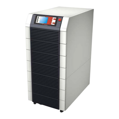
WÄRTSILÄ JOVYTEC L Series User manual

Operating Manual
Wärtsilä
JOVYTEC L 6kVA –10kVA
BAX 3297_en

Wärtsilä JOVYTEC L 6kVA –10kVA BAX 3297_en - 2 -
Index
Date
Name
Revision
0
08.04.2009
Technik
Original
1
2014-06-20
Chr. Fechteler
14/375
2
2015-07-22
Chr. Fechteler
15/381
3
2016-03-24
Chr. Fechteler
16/190
4
2018-01-30
D. Busboom
18/038
5
6
7
8
9
10

Wärtsilä JOVYTEC L 6kVA –10kVA BAX 3297_en - 3 -
Important notes
Please read these instructions carefully
These instructions contain specifications concerning safety, installation and work procedures that will help you
put our product to optimal use. They must be read carefully before beginning assembly and installation of the
product. They must be accessible to both the product’s assembler and operator.
Please keep these instructions in a safe place
They contain important specifications and notes concerning use of the product as well as notes concerning
questions and problems.
Validity
Our goods and services are subject to the general terms of delivery for products of the electronics industry as
well as our general sales conditions. We reserve the right to make changes to these instructions –in particular
as regards the technical data, operating instructions and the weights and dimensions –at any time. These
instructions correspond to the product’s technical version at the time of publication. Their contents are not part
of any contract but are for information purposes only.
Wärtsilä JOVYATLAS EUROATLAS GmbH reserves the right to make substantive and technical changes
regarding the content of these instructions without prior notification. Wärtsilä JOVYATLAS EUROATLAS GmbH
cannot be held liable for any errors or inaccuracies in these instructions, as there is no obligation to provide
regular updates.
Complaints
Complaints must be submitted to the manufacturer at the latest eight days after delivery of the product.
Copyright
Any disclosure, reproduction and/or copying of these instructions, by electronic or mechanical means, in whole
or in part, requires the express prior written consent of Wärtsilä JOVYATLAS EUROATLAS GmbH.
Copyright Wärtsilä JOVYATLAS EUROATLAS GmbH. All rights reserved

Wärtsilä JOVYTEC L 6kVA –10kVA BAX 3297_en - 4 -
TABLE OF CONTENTS
1. GENERAL NOTES 6
2. DESCRIPTION OF THE SYSTEM 7
3. GENERAL DESCRIPTION OF THE FUNCTION 7
4. TECHNICAL DATA 9
5. DIMENSIONS AND VIEWS 12
5.1 FRONT VIEW 12
5.2 REAR VIEW WÄRTSILÄ JOVYTEC L 6000 13
5.3 REAR VIEW WÄRTSILÄ JOVYTEC L 8000/10000 13
6. ELECTRICAL CONNECTION 14
6.1 ELECTRICAL CONNECTION WÄRTSILÄ JOVYTEC L 6000 15
6.1.1 ELECTRICAL CONNECTION FOR ONE MAINS FEEDING 16
6.1.2 ELECTRICAL CONNECTION FOR TWO MAINS FEEDING 17
6.1.3 ELECTRICAL CONNECTION FOR ONE MAINS FEEDING NON ISOLATED 18
6.2 ELECTRICAL CONNECTION WÄRTSILÄ JOVYTEC L 8000/10000 19
6.2.1 ELECTRICAL CONNECTION FOR ONE MAINS FEEDING 20
6.2.2 ELECTRICAL CONNECTION FOR ONE MAINS FEEDING NON ISOLATED 21
6.3 COMMISSIONING 22
6.4 SHUTTING-DOWN 22
7. OPERATING AND INDICATING ELEMENTS 23
7.1 FUNCTION OF LED AND FUNCTION KEYS 23
7.2 PARAMETERS 24
7.3 CONFIGURATION 25
7.4 TABLE OF PARAMETERS 25
7.5 MANUAL TESTING 26
7.6 OFFLINE MODE 26
7.7 FREE RUNNING MODE 26
7.7.1 FREE RUNNING ON 26
7.7.2 FREE RUNNING OFF 26
7.8 BYPASS TOLERANCE / BYPASS (DE-) ACTIVATION 27
7.8.1 FREE RUNNING ON, BYPASS DEACTIVATED 27
7.8.2 FREE RUNNING ON, BYPASS ACTIVATED 27
7.7.6 GENERATOR MODE 28
7.8 ERROR MESSAGES AND THEIR REMOVAL 28
7.8.1 OPTICAL AND ACOUSTICAL ERROR MESSAGES 29
8. SERVICE INFORMATION 30
9. REMOTE MONITORING 30

Wärtsilä JOVYTEC L 6kVA –10kVA BAX 3297_en - 5 -
9.1 CONNECTING THE UPS TO THE COMPUTER 30
9.2 ASSIGNMENT OF THE RS232 INTERFACE 31
9.3 USB PORT (OPTIONAL) 31
10. CUTOMISED OPTIONS 31
10.1 ELECTRONIC STOP FUNCTION 31
10.2 BATTERY SYMMETRY MONITORING (OPTIONAL) 32
11. INTERNAL MANUAL BYPASS 33
11.1. EXTERNAL BYPASS (OPTIONAL) 33
12. VOLT-FREE MESSAGES VIA THE RELAY CARD (OPTIONAL) 34
12.1 DESCRIPTION OF THE RELAY CARD 34
13.2 BATTERY OPERATION 37
13.3 SERVICE LIFE OF BATTERIES 37
13.4 INSTRUCTIONS FOR USING THE BATTERIES 37
14 NOTES ON MAINTENANCE 38
15. NOTES 39

Wärtsilä JOVYTEC L 6kVA –10kVA BAX 3297_en - 6 -
N O T E!
The UPS should be attached to the mains supply and switched on at the latest 4
weeks after receipt in order to prevent the battery discharging itself.
P L E A S E N O T E!
In order to exclude the possibility of overloading or constant switching over to bypass
due to consumer generated non-sinusoidal current peaks, no devices such as laser
printers, fax machines as well as devices operating with a similar technology should be
connected to the UPS. In cases where it is essential that such devices be operated then
a UPS must be selected whose capacity can match the maximum possible current
peaks. Devices with power reduction due to half wave power consumption, (e.g. coffee
machines, hair dryers) can lead to immediate destruction of the power-output stage. The
battery is not galvanically isolated from the mains so occurrence of a mains voltage at
the battery terminals is possible! The UPS unit does have an output transformer and is
therefore galvanically isolated from the mains!!
P L E A S E N O T E!
The batteries used are just designed for the required bridging time to meet the
nominal load of the UPS. Operation of the UPS unit in free running mode for a
longer period of time on battery can damage the batteries. This effect is due to
the nature of the battery since for a longer discharge period the final
discharging voltage is not reached.
P L E A S E N O T E!
These ups –systems are equipped with an galvanically isolated output transformer.
The secondary winding of the output transformer has two seperate windings with each
115V. These windings are connected in series to 230V. If an earthed output is needed, so
the input neutral and the output neutral have to be connected!!
1. General notes
The device may only be opened by trained specialists.
The system is to be connected up and earthed according to VDE regulations. Provisions of the local energy
–supply company must be observed.
The ventilation slits on the front and rear sides must not be covered and a distance from the wall of at least
100 mm is essential.
The UPS unit is built according to Protection Class IP 20 and is designed for installation in heated internal
spaces (at 20°C). A lower operating temperature lowers the bridging time.
No devices with a connecting cable in excess of 10 metres in length should be connected to the UPS. This
measure serves to ensure observance of the EMC standard.
No alterations should be made to the UPS unit. The warranty will expire in cases of inappropriate physical
interventions.

Wärtsilä JOVYTEC L 6kVA –10kVA BAX 3297_en - 7 -
P L E A S E N O T E !
The output of the UPS unit also carries a voltage in the case of a power failure!
This is why the installation engineer must mark the outputs and power
sockets on the UPS unit clearly according to EN 62040.
Input
Battery
Rectifier Inverter
Ouput
Manual Bypass
Input
Battery
Rectifier Inverter
Output
Manual Bypass
2. Description of the System
Power supply devices of this model are particularly suited for supplying important power consumers in
industry and the office such as personal computer, computer-controlled devices, PLCs and similar
equipment. The output voltage is sinusoidal. In normal cases the attached consumers are supplied with
power from the installed rectifier and installed inverter from the mains power supply network (online
operation). Any disturbances in the mains such as voltage peaks, voltage drops, harmonic distortions or
noises etc. are filtered out. The installed battery is constantly being charged up by means of a charging
rectifier with a charge preservation charging stage which is gentle on the batteries.
3. General description of the function
Normal operation
During normal operation the battery and the inverter are supplied with power via a rectifier (online operation).
The change-over from alternating voltage to direct voltage and back to alternating voltage again is achieved
by a sinusoid output voltage with a low distortion factor. The direct voltage is also needed for charging the
battery. The inverter supplies the attached consumers.
Figure 1: Block diagram “Normal operation“
Power failure
In the case of a power failure, the energy needed by the inverter is taken from the battery. The output voltage of
the inverter is still available.
Figure 2: Block diagram “Power failure“

Wärtsilä JOVYTEC L 6kVA –10kVA BAX 3297_en - 8 -
Input
Battery
Rectifier Inverter
Output
Manual Bypass
Input
Battery
Rectifier Inveter
Output
P L E A S E N O T E!
An operating fault can lead to total loss of power supply to the attached power
consumer loads! A power failure for a switched in manual bypass will lead to
crashing of the power consumer loads!
Fault in the inverter or an overload (bypass operation)
In the case of a fault occurring in the inverter or an overload, a switch-over device switches the load back to
the mains. This means that, in the case of a power failure, the connected consumers will no longer be
supplied with power.
Figure 3: Block diagram “Fault in the inverter“
Manual bypass (service bypass)
If there is a fault in the UPS unit and service work must be undertaken, the UPS unit is fitted with an internal
bypass for that purpose. When actuating the manual bypass, the load is directly supplied from the mains.
This means that, in the case of a power failure, the connected consumers will no longer be supplied with
power. When using the manual bypass it is essential to observe the formalism described in Chapter “internal
Manual Bypass”. Other procedures could lead to destruction of the UPS unit or crashing of the power
consumer loads.
Figure 4: Block diagram “Manual bypass“

Wärtsilä JOVYTEC L 6kVA –10kVA BAX 3297_en - 9 -
4. Technical data
6 kVA
Power
cos 0,7 ind.
6000VA / 4200W
Mains Input
Voltage
230V
Input Voltage Ranges
168V - 276V (0-100% Load)
140 - 159V (0-70% Load)
120 - 139V (0-40% Load)
Current
23A
Frequency
50Hz ±3Hz or 60Hz ±3Hz
Phase
Single phase
Power Factor
0,98
External Fuse
D02/35A
Battery build in
UPS - System
DC –Voltage
240V
Autonomy Time
8 Min. at 100% Load
12Min. at 80% Load
20Min. at 50% Load
50% Load
20 Min.
Type
Maintenance free sealed lead acid battery
Charging Time
< 8 h for 90%ige charging
Output
Voltage
230V Standard (208V / 220V / 240V adjustable by Panel)
Frequency
Automatic adjusted by UPS
Power Factor
0,7 ind.
Phase
single Phase
Distorsion
< 3% at linear Load
Overload Capability
100 to 125% for 60s
125 - 150% for 10s
Crest Factor
3 : 1
Efficiency
AC to AC
88 - 98% acc. to operation mode
Change over
performance
Voltage failure
0ms
Overload switch over
Automatic by UPS
Loudness
app. 1m Distance
< 55dB(A)
Environment
Temperature
0°C bis 40°C
+15 … +25°C (recommended)
Humidity
0% bis 95%, no condensing
Storage at …
20°C with build in Battery (recommended)
-20 bis +50°C without Battery
Interfaces
RS 232-Interface
Optional:
USB - Interface
Relay Card
AS/400 - Adapter
SNMP –Adapter
Supports power management and diagnosis such as BATTERY LOW, UPS
ON/OFF
Software is compatible with operating systems such as: Windows
95/98/NT/2000/XP, Novell, Unix, etc current operating systems
Dimensions
Width
257mm
Depth
590mm
Height
700mm
Weight UPS
ca. 123 kg
Weight UPS incl.
Battery
ca. 174kg incl. Batteries
Scope of Supply
Hardware/Software
USV-Device
Battery Cabinet according to Autonomy Time
Manua BAX 3297_en
Interface Cable
Software UPSMON

Wärtsilä JOVYTEC L 6kVA –10kVA BAX 3297_en - 10 -
8 kVA
Power
cos 0,7 ind.
8000VA / 5600W
Mains Input
Voltage
230V
Input Voltage Ranges
168V - 276V (0-100% Load)
140 - 159V (0-70% Load)
120 - 139V (0-40% Load)
Current
30,7A
Frequency
50Hz ±3Hz or 60Hz ±3Hz
Phase
Single phase
Power Factor
0,98
External Fuse
D02/35A
Battery build in
UPS - System
DC –Voltage
240V
Autonomy Time
5 Min. at 100% Load
8Min. at 80% Load
15Min. at 50% Load
50% Load
15 Min.
Type
Maintenance free sealed lead acid battery
Charging Time
< 8 h for 90%ige charging
Output
Voltage
230V Standard (208V / 220V / 240V adjustable by Panel)
Frequency
Automatic adjusted by UPS
Power Factor
0,7 ind.
Phase
single Phase
Distorsion
< 3% at linear Load
Overload Capability
100 to 125% for 60s
125 - 150% for 10s
Crest Factor
3 : 1
Efficiency
AC to AC
88 - 98% acc. to operation mode
Change over
performance
Voltage failure
0ms
Overload switch over
Automatic by UPS
Loudness
app. 1m Distance
< 65dB(A)
Environment
Temperature
0°C bis 40°C
+15 … +25°C (recommended)
Humidity
0% bis 95%, no condensing
Storage at …
20°C with build in Battery (recommended)
-20 bis +50°C without Battery
Interfaces
RS 232-Interface
Optional:
USB - Interface
Relay Card
AS/400 - Adapter
SNMP –Adapter
Supports power management and diagnosis such as BATTERY LOW, UPS
ON/OFF
Software is compatible with operating systems such as: Windows
95/98/NT/2000/XP, Novell, Unix, etc current operating systems
Dimensions
Width
342mm
Depth
740mm
Height
880mm
Weight UPS
ca. 178 kg
Weight UPS incl.
Battery
ca. 280kg incl. Batteries
Scope of Supply
Hardware/Software
USV-Device
Battery Cabinet according to Autonomy Time
Manua BAX 3297_en
Interface Cable
Software UPSMON

Wärtsilä JOVYTEC L 6kVA –10kVA BAX 3297_en - 11 -
10 kVA
Power
cos 0,7 ind.
10000VA / 7000W
Mains Input
Voltage
230V
Input Voltage Ranges
168V - 276V (0-100% Load)
140 - 159V (0-70% Load)
120 - 139V (0-40% Load)
Current
38,3A
Frequency
50Hz ±3Hz or 60Hz ±3Hz
Phase
Single phase
Power Factor
0,98
External Fuse
D02/50A
Battery build in
UPS - System
DC –Voltage
240V
Autonomy Time
10 Min. at 100% Load
15Min. at 80% Load
28Min. at 50% Load
50% Load
28 Min.
Type
Maintenance free sealed lead acid battery
Charging Time
< 8 h for 90%ige charging
Output
Voltage
230V Standard (208V / 220V / 240V adjustable by Panel)
Frequency
Automatic adjusted by UPS
Power Factor
0,7 ind.
Phase
single Phase
Distorsion
< 3% at linear Load
Overload Capability
100 to 125% for 60s
125 - 150% for 10s
Crest Factor
3 : 1
Efficiency
AC to AC
88 - 98% acc. to operation mode
Change over
performance
Voltage failure
0ms
Overload switch over
Automatic by UPS
Loudness
app. 1m Distance
< 65dB(A)
Environment
Temperature
0°C bis 40°C
+15 … +25°C (recommended)
Humidity
0% bis 95%, no condensing
Storage at …
20°C with build in Battery (recommended)
-20 bis +50°C without Battery
Interfaces
RS 232-Interface
Optional:
USB - Interface
Relay Card
AS/400 - Adapter
SNMP –Adapter
Supports power management and diagnosis such as BATTERY LOW, UPS
ON/OFF
Software is compatible with operating systems such as: Windows
95/98/NT/2000/XP, Novell, Unix, etc current operating systems
Dimensions
Width
342mm
Depth
740mm
Height
880mm
Weight UPS
ca. 178 kg
Weight UPS incl.
Battery
ca. 280kg incl. Batteries
Scope of Supply
Hardware/Software
USV-Device
Battery Cabinet according to Autonomy Time
Manual BAX 3297_en
Interface Cable
Software UPSMON

Wärtsilä JOVYTEC L 6kVA –10kVA BAX 3297_en - 12 -
5. Dimensions and views
5.1 Front view
UPS size
Depth
Width
Heights
6 kVA
590
257
700
8 kVA
740
342
880
10 kVA
740
342
880
Operating panel
Feed Roll

Wärtsilä JOVYTEC L 6kVA –10kVA BAX 3297_en - 13 -
TERMINAL RAIL
5.2 Rear View WÄRTSILÄ JOVYTEC L 6000
RS232 Interface with
Electronic Stop
USB –Interface
Fans
Relay Card
Terminal Rail
Pull Relief
Service –Bypass
Switch
TAE –Protection
Circuit
Mains Input Fuse
Output Fuse

Wärtsilä JOVYTEC L 6kVA –10kVA BAX 3297_en - 14 -
TERMINAL RAIL
5.3 Rear View WÄRTSILÄ JOVYTEC L 8000/10000
Relay Card with
Electronic STOP
USB - Interface
TAE –Protection
Circuit
RS 232 –Interface
with Electronic STOP
Mains Input Fuse
Battery Fuse
Terminal Rail
Fans
Service -
Bypassschalter

Wärtsilä JOVYTEC L 6kVA –10kVA BAX 3297_en - 15 -
P L E A S E N O T E!
The voltage L1´and L2´can be connected in series with the voltage L3´and L4´.
(Connection between L2´and L3´is standard delivery status). Both potentials can
also be connected in parallel (Customer whish). If there is no interconnection
between terminal 10 and terminal 17, than the output voltage is galvanically
isolated from mains and you will build an earthed isolated mains at the output of
the ups. This makes it necessary to use an isolation monitoring unit at the output
of the ups. At the standard delivery the connection for earthed output has
been made on manufacturer side!!
6. Electrical connection
6.1 Electrical connection WÄRTSILÄ JOVYTEC L 6000
The UPS unit is simply connected via terminals at the rear side of the ups. Before connecting the UPS, the
cover plate has to be removed. To insert the cables there are three cable inlets inside the cover plate. The
connection for the terminals is as follows:
1 = Battery +
2 = Battery –
3 = PE
4 = Feeding L1 from bypass (connection between terminal 4 and 5 is possible or separate feeding.
5 = Potential L1 internal from terminal 8
6 = Neutral for bypass (internal connection to terminal 9)
7 = PE for bypass
8 = Feeding L1 for mains input
9 = Neutral for mains input
10 = Neutral for connection to neutral output (earthed)
11 = PE for mains input
12 = Potential L1´(L1´= L1)
13 = Potential L2´ (The voltage between terminal L1´and L2´is 115V)
14 = Potential L3´
15 = Potential L4´(The voltage between terminal L3´and L4´is 115V)
16 = Neutral N (The voltage between terminal L1`(terminal 12) and N (terminal 16) is 230V)
17 = Neutral N (for connection with input neutral for earthed output voltage)
18 = PE Output
P L E A S E N O T E!
Only trained personnel are allowed to work on the UPS unit.
Observe all correponding safety regulations.
Marking of cables is to be according to DIN EN 60445!
When connecting to the UPS unit, ensure use of an adequately sized protective-
conductor connection!
P L E A S E N O T E!
When working on the batteries it is possible for dangerous situations to arise
due to a high DC voltage and high short-circuit currents.
This work on the device must only be conducted when accompanied by use of
suitable protective measures such as insulated tools, eye and hand protection
etc.

Wärtsilä JOVYTEC L 6kVA –10kVA BAX 3297_en - 16 -
6.1.1 Electrical connection for one mains feeding
1. Switch off input and output fuse at 6kVA - UPS on the rear side of the ups.
2. Dismantle the cover plate with a Phillips Screw Driver
3. Insert the cables into the cable inlets of the cover plate.
4. For connecting the ups please take attention to the instructions on the rear side of the ups.
5. Connect the mains input cable to the terminal rail at the terminals 8 (L1), 9 (N), 11 (PE).
6. Make sure, that a connection between 4 (L1) and 5 (L1) has been made
7. Connect the load output cable to the terminal rail at the terminals 12 (L1´), 16 (N), 18 (PE).
8. With this variance of connection you build an galvanically isolated output. This makes an
additional isolation monitoring unit necessary.
9. If an addditional battery cabinet is in use. Please connect the battery cable to the terminal at the
terminals 1 (B+), 2 (B-), 3 (PE). Attention: Please take care of the polarity!!
10. Mount the cover plate on the rear side of the ups.
11. Switch on the Input Fuse.
12. Switch on the Battery Fuse.
The work at the UPS is now finished.

Wärtsilä JOVYTEC L 6kVA –10kVA BAX 3297_en - 17 -
6.1.2 Electrical connection for two mains feeding
1. Switch off the input- and output switch at 6kVA - UPS on rear side of the UPS
2. Dismantle the cover plate with a Phillips Screw Driver
3. Guide the leads through the foreseen cut outs
4. For connecting the ups please take attention to the instructions on the rear side of the ups.
5. Connect the input cable to the terminals with the designation input 8 (L1), 9 (N), 11 (PE).
6. Make sure that the wire connection between the terminals 4 (L1) and 5 (L1) at the terminal rail bypass have
been removed.
7. Connect the bypass feeding to terminal rail at terminal 5 (L1), 6 (N), 7 (PE). (Take care that you don´t
exchange the L with N)
8. Connect the output cables to the terminals with the designation 12 (L1´), 16 (N), 18 (PE).
9. With this variance of connection a galvanically isolated output is set up. This requires an
additional isolation monitoring unit.
10. If an addditional battery cabinet is in use. Please connect the battery cable to the terminal at the
terminals 1 (B+), 2 (B-), 3 (PE). Attention: Please take care of the polarity!!
11. Fix the cover plate with a Phillips Screw Driver
12. Switch on the input switch
13. Connect the battery pack to the battery jack on rear side of the UPS
14. Switch on the output switch
15. The electrical connection is herewith already done
P L E A S E N O T E!
Both mains feeding must have the same connection.
Don´t exchange L1, N , PE, this will cause a short circuit which will destroy the UPS!!

Wärtsilä JOVYTEC L 6kVA –10kVA BAX 3297_en - 18 -
6.1.3 Electrical connection for one mains feeding non isolated
1. Switch off input and output fuse at 6kVA - UPS on the rear side of the ups.
2. Dismantle the cover plate with a Phillips Screw Driver
3. Insert the cables into the cable inlets of the cover plate.
4. For connecting the ups please take attention to the instructions on the rear side of the ups.
5. Connect the mains input cable to the terminal rail at the terminals 8 (L1), 9 (N), 11 (PE).
6. Make sure, that a connection between 4 (L1) and 5 (L1) has been made
7. Connect the load output cable to the terminal rail at the terminals 12 (L1´), 16 (N), 18 (PE).
8. Check if the connection between 10 (N) and 17 (N) is existent.
9. With this variance of connection you build an earthed output.
10. If an addditional battery cabinet is in use. Please connect the battery cable to the terminal rail at the
terminals 1 (B+), 2 (B-), 3 (PE). Attention: Please take care of the polarity!!
11. Mount the cover plate on the rear side of the ups.
12. Switch on the Input Fuse.
13. Switch on the Battery Fuse.
The work at the UPS is now finished.

Wärtsilä JOVYTEC L 6kVA –10kVA BAX 3297_en - 19 -
P L E A S E N O T E!
The voltage L1´and L2´can be connected in series with the voltage L3´and L4´.
(Connection between L2´and L3´is standard delivery status). Both potentials can
also be connected in parallel (Customer whish). If there is no interconnection
between terminal 6 and terminal 13, than the output voltage is galvanically
isolated from mains and you will build an earthed isolated mains at the output of
the ups. This makes it necessary to use an isolation monitoring unit at the output
of the ups. At the standard delivery the connection for earthed output has
been made on manufacturer side!!
6.2 Electrical connection WÄRTSILÄ JOVYTEC L 8000/10000
The UPS unit is simply connected via terminals at the rear side. Before connecting the UPS, the cover plate
has to be removed. To insert the cables there are three cable inlets inside the cover plate. The connection
for the terminals is as follows:
1 = Battery +
2 = Battery –
3 = PE
4 = Input L1 for mains
5 = Input N for mains
6 = Neutral connection with output neutral for earthed output.
7 = PE for mains
8 = Potential L1´(L1´= L1)
9 = Potential L2´(The voltage between L1´and L2´is 115V)
10 = Potential L3´
11 = Potential L4´ (The voltage between terminal L3´and L4´is 115V)
12 = Neutral N (The voltage between L1´(terminal 12) and N (terminal 16) is 230V)
13 = Neutral N (for the connection between neutral N input and neutral N output)
14 = PE Output

Wärtsilä JOVYTEC L 6kVA –10kVA BAX 3297_en - 20 -
6.2.1 Electrical connection for one mains feeding
1. Switch off input and battery fuse on the rear side of the ups.
2. Dismantle the cover plate with a Phillips Screw Driver
3. Insert the cables into the cable inlets of the cover plate.
4. For connecting the ups please take attention to the instructions on the rear side of the ups.
5. Connect the mains input cable to the terminal rail at the terminals 4 (L1), 5 (N), 7 (PE).
6. Connect the load output cable to the terminal rail at the terminals 8 (L1´), 12 (N), 14 (PE).
7. With this variance of connection a galvanically isolated output is set up. This requires an
additional isolation monitoring unit.
8. If an addditional battery cabinet is in use. Please connect the battery cable to the terminal rail at the
terminals 1 (B+), 2 (B-), 3 (PE). Attention: Please take care of the polarity!!
9. Mount the cover plate on the rear side of the ups.
10. Switch on the Input Fuse.
11. Switch on the Battery Fuse.
The work at the UPS is now finished.
This manual suits for next models
3
Table of contents
Other WÄRTSILÄ UPS manuals

WÄRTSILÄ
WÄRTSILÄ JOVYSTAR COMPACT S BAX 5452 User manual

WÄRTSILÄ
WÄRTSILÄ JOVYTEC P Series User manual

WÄRTSILÄ
WÄRTSILÄ JOVYATLAS POWERMASTER S 6000-P User manual

WÄRTSILÄ
WÄRTSILÄ JOVYCUBE 160 User manual

WÄRTSILÄ
WÄRTSILÄ JOVYREC D600 G120/10 User manual

WÄRTSILÄ
WÄRTSILÄ JOVYSTAR HP 200 kVA User manual

WÄRTSILÄ
WÄRTSILÄ JOVYTEC PMS 2002K User manual

WÄRTSILÄ
WÄRTSILÄ JOVYTEC POWERMASTER PMS 6000 User manual

WÄRTSILÄ
WÄRTSILÄ JOVYSTAR-DELTA User manual