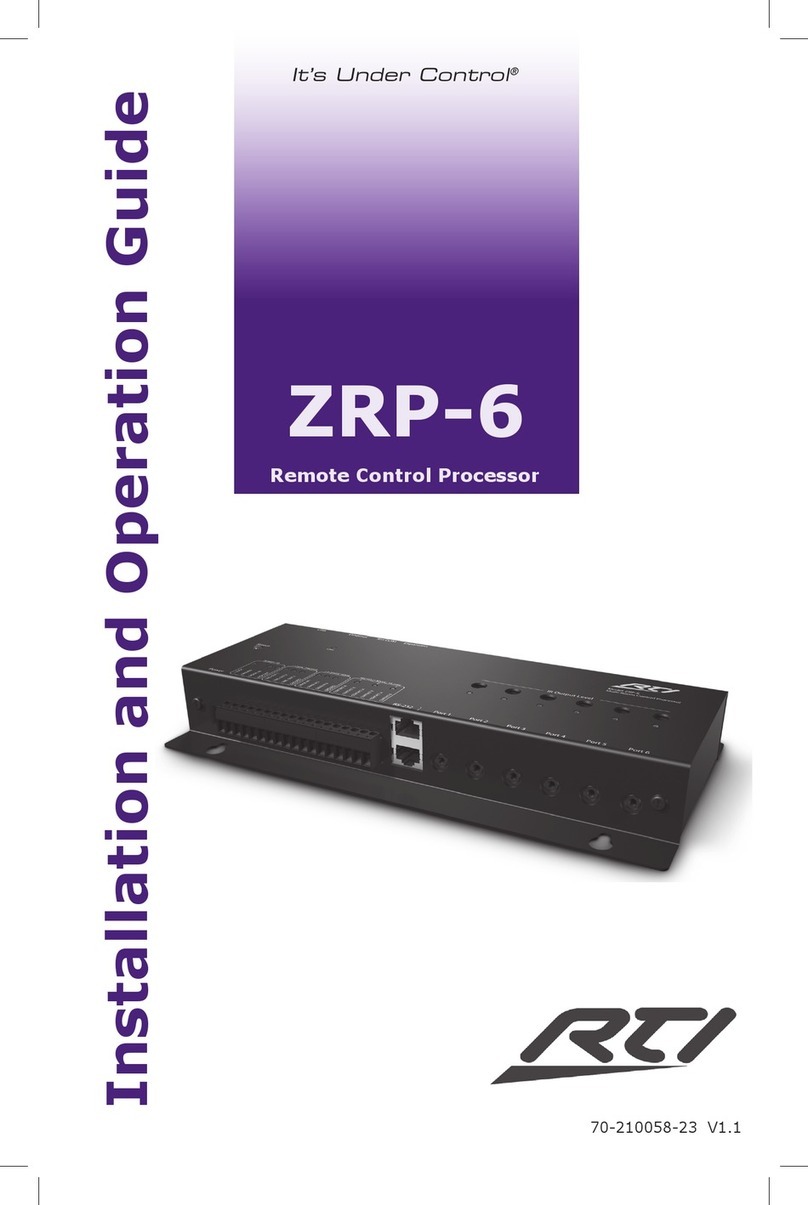
Slee MTM II User manual

DESIGN &
MANUFACTURING
MADE IN GERMANY
O P E R A T I N G
M A N U A L
TISSUE PROCESSOR
MTM II
COSTEFFECTIVE PREMIUM TISSUE PROCESSING
HIGHEST RELIABILITY
EASY CLEANING

2 Manual_MTM_II_2021-10-010.00_EN.docx

Manual_MTM_II_2021-10-010.00_EN.docx 3
CONTENTS
1. INTENDED USE
............................................................ 4
2. SYMBOLS
............................................................ 4
3. SAFETY NOTES
............................................................ 5
4. COMPONENTS
............................................................ 8
5. SPECIFICATIONS
............................................................ 9
6. UNPACKING AND INSTALLATION
............................................................
11
7. INITIAL OPERATION
............................................................ 14
8. REAGENT MANAGEMENT
SYSTEM
............................................................ 26
9. OPERATION
............................................................ 41
10. ALARMS
............................................................ 69
11. CLEANING AND MAINTENANCE
............................................................ 82
12. SERVICE
............................................................ 84
13. OPTIONAL ACCESSORIES
............................................................ 88
14. WARRANTY
............................................................
89
15. DISPOSAL
............................................................ 89

4 Manual_MTM_II_2021-10-010.00_EN.docx
1. INTENDED USE
The vacuum tissue processor MTM II is intended for automated fixation, dehydration
and paraffin infiltration of histological samples for professional use in routine and
research laboratories in the fields of biology, medicine and industry.
MTM II is equipped with an enhanced heat exchanger (EHE) that allows conventional
overnight tissue processing, semi-rapid processing of larger samples and fast processing
of biopsies.
The MTM II tissue processor recycles the air utilized to move the reagents to and from
the processing chamber. An effective charcoal filter on the external air-outlet reduces
the exhaust fumes to acceptable and safe levels. The wax and reagent bottles can be
rapidly removed and easily reinstalled in their housing slots. The control devices
(hardware and software) are based on the most up-to-date processing control
technologies. Up to 18 different programs can be permanently stored and be easily
modified. The 18th program is a special “REVERSED” program that is used to de-process
samples that have not had good infiltration.
During a run, every step and action is displayed on the screen, such as current step and
function (emptying, filling, etc.), processing chamber and wax heating chamber
temperatures, processing chamber pressure, completion time and date, and any other
parameter necessary to simplify the use of the instrument. In the event of power
failures, the computer saves all the data necessary to restart the process exactly where it
was interrupted. If the interruption happens during the wax stages, particular
precautions are taken to guarantee melting before any wax filling or emptying begins.
2. SYMBOLS
Dangers, warnings and cautions are marked by this symbol
Flammable solvents and reagents are marked with this
symbol.
Special instructions regarding the operation of the
instrument are marked by this symbol

Manual_MTM_II_2021-10-010.00_EN.docx 5
i
3. SAFETY NOTES
The institution which owns the unit and the persons working with the unit, servicing or
repairing it have the responsibility for a hazard-free use.
•
Severe damage can result if the instrument is connected to a
power supply different from the rating stated in the identification
tag placed on the rear of the instrument.
•The instrument must NEVER be used without being connected to
an appropriate and fully efficient ground connection.
•If damages due to transport occur, DO NOT use and DO NOT
connect the instrument to a power source. Contact our technical
service.
•This instrument has been designed to work 24/7; for this reason
and for operative precautions, the power switch is placed on the
rear of the instrument.
•Access to the instrument’s internal components is reserved only to
specialists trained in the service of the instrument.
•Always disconnect the processor from the electrical main source
before accessing the electronics and internal parts.
•BEFORE replacing fuses, disconnect the instrument from the power
source.

6 Manual_MTM_II_2021-10-010.00_EN.docx
•
Always make certain to correctly engage the reagent bottles.
•DO NOT open the processing chamber lid when the instrument is
working without following the instructions contained in this
manual.
•Use specific precautions in handling flammable reagents such as
ethanol (wear protective gloves and eyeglasses).
•Use specific precautions in handling liquid waxes as they can cause
burns.
•The emptying and filling of reagent bottles must only be done only
by qualified technicians.
•Due to the presence of flammable substances inside reagents
bottles, it is recommended to:
oAvoid smoking near the instrument
oAvoid using open flames near the instrument (e.g. Bunsen
burner)
oDO NOT wear clothes that can create electrostatic charges
while handling reagents (wool, synthetic fibers, etc.)
•Contaminated reagent waste must be disposed off in accordance
with all applicable local laws, ordinances and safety standards.
•Use only original spare parts supplied by the manufacturer or by
authorized dealers.
•DO NOT extract bottles, replace reagents or do other maintenance
operations when the instrument is operating.
•To complete the knowledge on the instrument safety please read
also the chapter SAFETY DEVICES near the end pages of this
manual.

Manual_MTM_II_2021-10-010.00_EN.docx 7
3.1ELECTRICAL POWER CONNECTION
Do not use any extension lead.
Make sure that electric power is constant:
•
This should be examined during installation of the unit by a
competent person.
•Use a dedicated fuse for the unit.
•Do not connect another unit to the same power circuit.
•Before turning on the instrument, check if the voltage of the mains
supply is identical with the name plate of the unit.

8 Manual_MTM_II_2021-10-010.00_EN.docx
4. COMPONENTS
The Slee vacuum tissue processor MTM II is provided with the following standard
components:
MTM I MTM II
Basic unit with rotary valve
•
•
Enhanced heating element (EHE)
•
15’’ Color-LCD-Touchscreen
•
•
Cassette basket
(2x 150 cassettes; stainless steel)
•
•
10x reagent container
•
•
4x+1 paraffin container
•
•
2x System cleaning solution container
•
•
1x charcoal container
•
•
1x condensate container
•
•
Sieve insert
•
•
Mains cable
•
•
Operation manual
•
•

Manual_MTM_II_2021-10-010.00_EN.docx 9
5. SPECIFICATIONS
Type
Vacuum tissue processor
Principle
pressure / vacuum
Reagent containers
10 reagent container
4+1 paraffin container
2 system cleaning fluid container
Volume
2.5 litres
Reagent agitation
air bubbling
Capacity
300 histology cassettes
2 baskets (150 cassettes each)
Temperature range
MTM I
55 – 65 °C (paraffin)
RT, 35 – 45 °C (reagents)
MTM II
55 - 65 °C (paraffin)
RT, 35 - 45 °C (reagents)
EHE-element for preheated reagents
Pressure range
Vacuum
400 hPa (0.4 bar)
Pressure 1200 hPa (1.2 bar)
Programmes
18
Safety aspects
closed system
1 charcoal filter
Sample safety
remote alarm system (optional)
UPS (optional)

10 Manual_MTM_II_2021-10-010.00_EN.docx
Vacuum function
Programmable, vacuum or pressure
Cleaning cycles
automatic system cleaning cycle
paraffin cleaning cycle
Delay timer
up to 14 days, 23 hours, 59 minutes
Display
15'' Color-TFT-Monitor, Touchscreen
Interfaces
USB
Fill and Drain
Manual or automatic remote filling
and draining
Reagent Management
fully automatic, programmable
automatic shifting of reagents
Power
100 - 240 V 50/60 Hz
1500 W
IEC1010 classification
Protective Class 1, Pollution deg. 2
Overvoltage category II
800 V impulse (115 V version
1500 V impulse (230 V version)
Dimensions and weight
[width x depth x height]
720 mm x 600 mm x 1.080 mm without monitor
720 mm x 600 mm x 1.430 mm with monitor
Weight
without accessories
MTM I
120 kg
MTM II
135 kg

Manual_MTM_II_2021-10-010.00_EN.docx 11
6. UNPACKING AND INSTALLATION
Before moving or transporting the instrument, it is essential to carefully read this
chapter, paying particular attention to the instrument setup instructions.
The warranty is invalid if the instrument is improperly operated. Be certain to follow the
instructions and recommendations provided by this manual. The manufacturer is not
responsible for damages resulting from improper operation or handling of the
instrument.
Pay particular attention to the outside of the shipping container. In the event of
concealed damage, save all shipping crates and packing material. DO NOT unpack the
instrument if damage is apparent. Immediately notify the carrier of any damage and
contact the shipper to initiate any claims.
6.1 UNPACKING THE INSTRUMENT
The proper steps to be taken are:
Open the top of the box
Lift the side walls out of the way
Raise the instrument to the vertical position
Remove the plastic layers that wrap the instrument
Carefully check the external condition of the instrument. In the event of evident
damage, DO NOT connect the instrument. Immediately notify the carrier and promptly
contact the seller
For the setup of the instrument, see the specific chapter (Installation and Start-up) in this
manual.
Save the box and all the internal packaging in the event that the unit requires future
shipment.

12 Manual_MTM_II_2021-10-010.00_EN.docx
6.2 INSTALLATION SITE REQUIREMENTS
The site for installation should meet the following requirements:
•
A maximum ambient temperature of +10 °C to +35 °C
•
Avoid vibrations, direct sunlight and strong temperature variations
•
The instrument must be set up in a well ventilated area free from any ignition
sources.
•
A free ventilation of fresh air from underneath the instrument should be
guaranteed
6.3INSTALLATION
After unpacking and the electrical connection to the main line the following steps have
to be performed to prepare the instrument for its use.
•
Installation of the charcoal filter on the slot C1. Remove the cap from the
charcoal filter bottle and make a hole with a screwdriver or a pencil in the
tape that seals the air intake on the top rear of the bottle.
•
Connect the LCD screen. The LCD screen is transported unconnected in a
separate cardboard box. The screen must be placed on the top left of the
instrument housing. The electrical connection is made by connecting the three
connector on the instrument rear panel.
•
Connect the instrument to the main power. The main power supply
connection must provide:
230 Volt versions: 230 V AC +/- 10%, 50 Hz, 5A, grounded.
115 Volt versions: 115 V AC +/- 10%, 60 Hz, 10A, grounded.
It is recommended that the instrument is plugged into a wall socket equipped
with Ground Fault Circuit Interruption (GFCI) protection, as an additional
electrical safeguard.
In addition to the MTM II anti-blackout feature, an uninterruptible power
supply can be utilized to provide power in the event of power outages and
some protection against power fluctuations, line noise and power spikes.
It is highly recommended that the instrument be operated away from heat
(radiators, stoves, direct sunlight, etc.) and moisture (sinks, drains, etc.).

Manual_MTM_II_2021-10-010.00_EN.docx 13
6.4PACKAGING AND/OR PREPARATION FOR TRANSPORT
To transport the instrument, perform the following steps:
•Remove all reagents (waxes included) from their bottles.
•Remove and close, with the proper threaded cap, the charcoal filter bottle,
put also some adhesive tape on the air inlet to avoid charcoal pellets to get
out.
•Transport the charcoal filter bottle separately from the instrument, wrapped
and securely closed in a protective nylon bag.
•If the original box has been saved, follow the unpacking instructions in the
reverse order, using all the interior packaging to avoid serious damage to the
instrument during shipping.
6.5TRANSPORTATION
Before shipping, please keep in mind that:
•The instrument is fragile;
•The instrument is equipped with electronic parts;
•Contact with water and/or any other liquid is to be avoided; please ensure
that the internal plastic protection bag that wraps the instrument is utilized;
•Transporting and storing temperature(s) must be between -10 °C to +50 °C;
•Using the original box, the instrument is to be transported horizontally;
•Transporting the instrument vertically is highly discouraged as its centre of
gravity is quite high.

14 Manual_MTM_II_2021-10-010.00_EN.docx
7. INITIAL OPERATION
7.1 MAIN MENU
The user interface is based on “Touch Screen” technology. Therefore there isn’t any
traditional keyboard, all the instrument functions are activated by a finger touch.
7.2 EHE (ENHANCED HEAT EXCHANGER)
The EHE (Enhanced Heat Exchanger) is a device capable to warm up the reagents
(container 01 to 10) during their transfer to the SPC. The heating of the reagents up
to 55 °C to 60°C allows performance of faster processes especially for very small
samples (biopsies).
The EHE device is capable to increase the reagents temperature of 30-35°C without
relevant delays; the reagents filling lasts only a few seconds more (approx. 15’’) than
the filling made directly without using the EHE.
The reagent heating up to 50 °C to 60 °C allows the reduction of the processing time,
in the MTM II this reduction is increased due to the fact that the reagent heating is
made during the reagents filling (through the EHE) without any delay.

Manual_MTM_II_2021-10-010.00_EN.docx 15
The EHE is intended to perform fast BUT SAFE reagents heating; this is accomplished
thanks to safety devices but also thanks to its special conformation, the reagent
during its transfer into the EHE is never in contact with hot spots so its temperature is
increased in a homogeneous and gentle way. In the SETUP screen, the first row on the
top indicates the current software version.
7.3 EHE ACTIVATION
The EHE must be activated by this function in order to keep it at the default
temperature of 65°C when the MTM II is NOT processing to make sure that it will be
always ready to
perform a fast processing program.
During a process the EHE is set (independently from the setup activation) following
this
plan:
• Warm if in the running process one of the steps is scheduled to use the EHE.
• The EHE is switched OFF if no steps in the running process are scheduled for using
the EHE.
• Switched OFF after the last step/tank with EHE of the running process has been filled
into the SPC.
• At the end of a process the EHE is set ON to be ready to eventually perform a fast
process (but only if set active here).
By this function it is possible to set inactive the EHE in case it is known that the MTM II
will not (never or for a long time) be used for fast tissue processing. In this case it is
IMPORTANT to know that if a fast process is started there will be a delay up to 20
minutes for the EHE pre-heating!
By setting the EHE inactive it is possible to save electrical energy, please consider that
the EHE power is 700 Watts, when it is warm the power absorbtion goes down to
approximately 350 Watts, still this power has a significant impact on your laboratory
electricity bill, especially considering that a tissue processor is made to work 24/7 all
year
long.
7.4SOFTWARE VERSION
In the SETUP screen, under section PARAMS SETUP, the current software version is
displayed on the top right.

16 Manual_MTM_II_2021-10-010.00_EN.docx
7.5 LANGUAGES
Seven languages are currently available: English, French, German, Italian, Spanish, Czech
and Turkish.
7.6DATE FORMAT
In the USA the date format is: month/day/year. In Europe the format is: day/month/year.
Also the time is displayed in a different way. Here it is possible to choose the format.
7.7 ELEVATION
The ambient pressure is depending on the site elevation from the sea level (approx. 100
HPa less every 1.000 meter for the first 2000 meters). It is important to program the
instrument according to the level at which it is installed in order to avoid it to require the
air pump to reach differentials of pressure (levels of vacuum) impossible to make
especially when the elevation is higher than 800-1000 meters.
7.8 L/L ALARM
The displays of the ALERTs during the processing (low level not blocking alarms) can
here be enabled/disabled.
7.9 EOP SIGNAL
The End of Process acoustic signal can here be enabled/disabled.
7.10 PRINTER PORT
If the printer is not used/installed its port can/should be disabled. In this way the
program execution will be faster.
7.11 DATA BACKUP
From this function it is possible to enable/disable the instrument automatic data backup.
The instrument is equipped with a USB interface. Data backup can be performed
manually in the service menu, or it can be enabled automatic once a day. The backup
will save files with data regarding: process programs, settings, calibrations, progressive
data, etc. In case of memory failure, after its substitution, it will be possible to restore
the instrument data.
In case of instrument failure the USB memory must be
removed from the USB interface and stored in a safe place
available for service technicians. If the automatic data
backup is enabled a USB memory stick with sufficient free
memory must be inserted into the USB interface. Every 3 or
4 months it is advisable to substitute it with a new one.

Manual_MTM_II_2021-10-010.00_EN.docx 17
7.12 SPC LID OPENED/CLOSED SENSOR
The SPC lid status is controlled by a micro switch sensor. If the lid is closed but the
system displays that it is open, probably the micro switch is broken or out-of-position.
Waiting for service, from this function the sensor can be disabled, after that it is possible
to continue to operate the instrument.
If the micro switch is disabled the SPC lid indicator will show the label “DISAB.” Please
note that the sensor can reveal the lid complete opening but cannot sense its perfect
closing. Thus if the lid is simply turned down but the lock is not engaged, the sensor
may indicate lid closed, but the instrument will not be available for processing. The
instrument will allow the process or purge start but soon it will issue an alarm caused by
the impossibility to create vacuum or pressure in the SPC. Please always check the
correct lid closing and lock engagement before the start of any kind of operation.
7.13WWC SETPOINT
This function allows the setting of the WWC target temperature. The range is 55 °C to
65 °C. It is advisable to set its value to the highest point compatible with the laboratory
procedures. Particularly it is necessary to set the value at least 2°C over the declared
paraffin melting point. For example for paraffin with a melting point of 56 °C to 58 °C
the correct WWC target temperature would be 60°C.
7.14 REMOTE FILL/DRAIN CALIBRATION
This procedure allows the calibration of the volume of reagent filled from port 18 during
the RFD cycle (Remote Fill/Drain). To find the right value proceed as follow:
using the RFD execute a fill in one of the reagent bottles in a condition as close as
possible to the normal operation.
With a system sufficiently precise (+/- 10ml) take a measurement of the filled reagent
Set the calibration value considering that every increase/decrease of 1 corresponds to +/-
5-7 ml. Repeat the filling with the RFD to check if the correction has given the right
result. The standard precision of the RFD is +/- 1.5%, which corresponds, respect to the
standard value of 2.5 litres, to a maximum of 2.538 litres and a minimum of 2.463 litres.
Given that the MTM II can work properly with the bottles charged from a minimum of
2.4 to a maximum of 2.6 litres, the above cited values are compatible with the correct
functioning of the processor in normal conditions (from 1 to 300 standard cassettes).
It is important to consider that the reagent bottles, as well as any kind of plastic object,
are subject to ample dimensional variations due to: manufacturing tolerances, ambient
temperature, reagent temperature, aging and wearing.
The two level indicators placed in the bottle front correspond to the above cited values.
But due to what explained about plastic objects dimensional variance their level may not
correspond exactly to 2.4 – 2.6 litres.

18 Manual_MTM_II_2021-10-010.00_EN.docx
Furthermore, to guarantee the almost complete reagent filling, the bottles are placed in
the instrument slots in a way to be 3.5° inclined toward the front. In this position the
indicators are not true. The upper one will correspond to approximately 2.5 litres.
So the indicators are made for usage with the bottle on the horizontal position, outside
the instrument, during manual filling.
7.15UNINTERRUPTIBLE POWER SOURCE (UPS)
The MTM II can be equipped with an optional UPS. To be recognized by the MTM II
computer the UPS must be enabled by this function, as well as it can be disabled in case
of malfunctions. Please note that both enabling and disabling are related only to the
MTM II computer -> UPS unit communications. Even if disabled by this function, the UPS
will continue to supply power to the MTM II but its state will not anymore shown and
considered. In case of an attempt to enable the UPS when the UPS is not installed, the
command will be refused. In case of serious malfunctions of the UPS it may be not
sufficient the software disabling, in this case it is advisable or necessary to physically
disconnect it from the MTM II. Please call our technical service to perform the repair or
the disconnection.
7.16SCREEN SAVER TIME
After a period of not utilization of the touch screen, the LCD screen is completely
switched off to extend its life span and save energy.
This function allows the setting of the panel ON time:
- the minimum time is 10 minutes
- the maximum time is 90 minutes
The tissue processor will continue to work perfectly even when the screen is switched
off, by touching any point in the screen surface it will be switched on in not more than
2 seconds and the MTM II computer will emit a beep to confirm. It is advisable to not
press more than one time the screen surface and wait for the screen data and pictures
to be visible before to perform any command. The first touch will not be considered a
command but any subsequent touch may be recognized as a command.

Manual_MTM_II_2021-10-010.00_EN.docx 19
7.17PASSWORD SETUP
The MTM II software includes a password system that allows the access restriction to
separate functions of the instrument.
Password general rules:
•
every time the password is requested there are 15 seconds time to type it and
press ENTER to confirm, after that time, if ENTER is not pressed, the system
goes back to the originating screen
•
in case of wrong password the system shows a specific error message and after
3 seconds goes back to the originating screen
•
after three wrong password insertions, the system issues the ALERT 34 (see
Alarms chapter), but the system continues to work and it is possible to continue
to type passwords
•
the password length is from 1 to 6 characters or numbers (mix is allowed)
•
also empty spaces are omitted in the password composition

20 Manual_MTM_II_2021-10-010.00_EN.docx
Enable/Disable Password
This function allows the enabling and disabling of the Password. If the password is not
active the systems requires the definition of a new one.
If the password is active the system allows the disabling by typing the current password
correctly. We recommend to carefully keep note of the password before the activation
because once activated there is no way to deactivate it without knowing it. In case the
password is lost it is necessary the intervention of our technical service to deactivate or
retrieve it!
During the activation the password is clearly shown on the screen to avoid typing
mistakes, later on, to avoid others to see the typed password, in place of letters or
number it is shown an asterisk.
Password modification
The password can be modified any moment from this function, but of course, the
modification is allowed only after the correct typing of the current password. We
recommend to carefully keep note of the new password before the modification
because once modified there is no way to deactivate or modify it without knowing the
current one. In case the password is lost it is necessary the intervention of our technical
service to deactivate or retrieve it!
Table of contents
