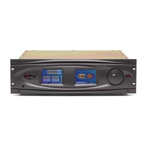
Soundfield DSF-3 MKII User manual

DSF-3 MKII
Digital
Surround Processor
User
Guide
Version 1.0

SoundField DSF-3
User Guide
Contents
Page 2
CONTENTS:
Safety Information - - - - - - - - - - 3
Controls - - - - - - - - - - - 4-10
Interfacing the DSF-3 with the DSF-2 Digital Broadcast - - - - - 11
Microphone System For Live Surround Broadcast
Audio Specification - - - - - - - - - - 12
Warranty - - - - - - - - - - - 13

SoundField DSF-3
User Guide
How Does it Work?
Page 3
SAFETY
INFORM
A
TION
• This equipment must be EARTHED.
• Only suitably trained personnel should service this equipment.
• Please read and take note of all warning and informative labels.
• Before starting any servicing operation, this equipment must be isolated from the AC supply
(mains) by removing the incoming IEC mains connector.
• Fuses should only be replaced with ones of the same type and rating as that indicated.
• Operate only in a clean, dry and pollutant-free environment.
• Do not operate in an explosive atmosphere.
• Do not allow any liquid or solid objects to enter the equipment. Should this accidentally occur
then immediately switch off the unit and contact your service agent.
• Do not allow ventilation slots to be blocked.
Cleaning
For cleaning the front panels of the equipment we recommend anti-static screen cleaner sprayed
onto a soft cloth to dampen it only.
Explanation
of
Warning Symbols
The lightening flash with arrow head symbol within an equilateral
triangle is intended to alert the user to the presence of dangerous
voltages and energy levels within the product’s enclosure that may
be of sufficient magnitude to constitute a risk of electric shock or
injury.
The exclamation mark within an equilateral triangle is intended to
prompt the user to refer to important operating or maintenance
(servicing) instructions in the

SoundField DSF-3
User Guide
Controls
Page 4
CONTROLS
Input
Page
1.
Input Trim
The inputs can be level trimmed by +/- 10dB in 1dB steps.
To change the input trim press the “Trim” button - this will change the display to show the trim level
in the middle of the screen – and use the rotary controller to alter the level.
To return back to the main screen either press the “Trim” button again or wait for the gain screen to
automatically time out.
2. End
Fir
e
The End Fire mode should be selected when the microphone is horizontally pointed ( ) at the
sound source as you would with a flashlight. Selecting End Fire maintains the correct three-
dimensional perspective in both surround and stereo when the mic is used in the horizontal
position.
If you do not select this mode when the microphone is horizontal it will result in the Front/Back
depth information and the Up/Down height information being reversed. This mode is particularly
necessary when the microphone is mounted in a Rycote or on a fishpole and pointed directly at the
sound source.
To enable End Fire press the “End Fire” button - this will change the display to show the End Fire
status in the middle of the screen – further presses of the “End Fire” button will toggle the status
of End Fire on and off.
To return back to the main screen either press the “End
Fir
e
” button again or wait for the gain screen
to automatically time out.

SoundField DSF-3
User Guide
Controls
Page 5
3.
Invert
The INVERT mode maintains the correct three-dimensional perspective in both surround and
stereo when the microphone is suspended upside down above the sound source ( ). Not
selecting this mode with the mic suspended will result in the Left/Right width information and
Up/Down height information being reversed. It is important to document the status of the Invert
switch when making B-Format recordings for later post production.
To enable
Invert
press the “
Invert
” button - this will change the display to show the
Invert
status
in the middle of the screen – further presses of the “
Invert
” button will toggle the status of
Invert
on and off.
To return back to the main screen either press the “
Invert
” button again or wait for the gain screen to
automatically time out.
4.
High Pass Filter
The variable High-Pass filter – second order Butterworth – will filter the incoming microphone
signals and will affect all output signals. Enabling the High-Pass filter is ideal for removing
unwanted low frequency rumble such as wind noise, etc.
To enable the
High Pass Filter
press the “
High Pass Filter
” button - this will change the display
to show the
High Pass Filter
status in the middle of the screen – further presses of the “
High
Pass Filter
” button will toggle the status of
Invert
on and off and the rotary controller will alter
the cut-off frequency.
To return back to the main screen either press the “
High Pass Filter
” button again or wait for the
gain screen to automatically time out.

SoundField DSF-3
User Guide
Controls
Page 6
Orientation Page
1. Rotate
Rotates the microphone’s pick up through a full horizontal 360º in 10º steps and redefines the
front centre of the stereo and surround image.
To change the rotation press the “Rotate” button - this will change the display to show the angle of
rotation in the middle of the screen – and use the rotary controller to alter the rotation.
To return back to the main screen either press the “Rotate” button again or wait for the gain screen to
automatically time out.
2. Zoom
Zoom allows you to focus in on the front or the rear of the microphone.
To change the zoom press the “Zoom” button - this will change the display to show the amount of
zoom in the middle of the screen – and use the rotary controller to alter the rotation.
To return back to the main screen either press the “Zoom” button again or wait for the gain screen to
automatically time out.
3. Front and Rear Tilt
Tilt allows you to tilt the microphone up or down by +/- 45º. There are individual tilts for the
front and the rear channels of the surround outputs to accommodate an umbrella effect, where
both the front and the rear of the microphone is in essence tilted downwards.
To change the front and rear tilt press the “Fr Ht or Re Ht” button - this will change the display to
show the angle of tilt in the middle of the screen – and use the rotary controller to alter the tilt.
To return back to the main screen either press the “Fr Ht or Re Ht” button again or wait for the gain
screen to automatically time out.

SoundField DSF-3
User Guide
Controls
Page 7
Surround Output Page
The Surround Output Page shows the surround sound output bargraphs and allows you to control the
parameters of the available output pairs. In the case of 5.1 the output pairs are L/R, C. LFE and
LS/RS.
The L/R and LS/RS output Page:
1.
L/R, LS/RS Level
The L/R, LS/RS output pairs can be level trimmed by +/- 10dB in 1dB steps.
To change the output level press the “Level” button - this will change the display to show the level in
the middle of the screen – and use the rotary controller to alter the level.
2. Width
This control varies the stereo image from zero degrees (mono) through 90 degrees (standard stereo
coincident pair) to an extra wide stereo 180 degrees. The effect of the Angle control can be viewed
on the screen.
To change the Width press the “Width” button and use the rotary controller to alter the gain.
3.
Polar Pattern
The Polar Pattern control is continuously variable ranging from Omni through Sub-Cardioid,
Cardioid, Hyper-Cardioid to Figure-of-eight and sets the polar patterns used for the stereo pair.
To change the Pattern press the “Pattern” button and use the rotary controller to alter the gain.

SoundField DSF-3
User Guide
Controls
Page 8
4.
Delay
A variable delay control is available for the LS/RS pair and can be varied by upto 40ms
in 1ms steps.
To change the delay press the “Delay” button and use the rotary controller to alter the delay.
5.
Low Pass Filter
A low pass filter is provided with a cut-off frequency ranging from 20KHz to50Hz.
To change the cut off frequency press the “LPF” button and use the rotary controller to alter the
frequency.
6.
High Pass Filter
A high pass filter is provided with a cut-off frequency ranging from 20Hz to 200Hz.
To change the cut off frequency press the “HPF” button and use the rotary controller to alter the
frequency.
The C, LFE output Page:
1.
C, LFE Level
The C and LFE output channel can be level trimmed by +/- 10dB in 1dB steps.
To change the output level press the “Level” button - this will change the display to show the level in
the middle of the screen – and use the rotary controller to alter the level.
2.
Polar Pattern
The Polar Pattern control is continuously variable ranging from Omni through Sub-Cardioid,
Cardioid, Hyper-Cardioid to Figure-of-eight and sets the polar patterns used for the stereo pair.
To change the Pattern press the “Pattern” button and use the rotary controller to alter the gain.

SoundField DSF-3
User Guide
Controls
Page 9
3.
Delay
A variable delay control is available for the LS/RS pair and can be varied by upto 40ms
in 1ms steps.
To change the delay press the “Delay” button and use the rotary controller to alter the delay.
4.
Low Pass Filter
A low pass filter is provided with a cut-off frequency ranging from 20KHz to50Hz.
To change the cut off frequency press the “LPF” button and use the rotary controller to alter the
frequency.
5.
High Pass Filter
A high pass filter is provided with a cut-off frequency ranging from 20Hz to 200Hz.
To change the cut off frequency press the “HPF” button and use the rotary controller to alter the
frequency.

SoundField DSF-3
User Guide
Controls
Page 10
REAR
P
ANEL
1. MAINS POWER INLETS - fully redundant power supply inlets.
2. Ethernet Port – for future expansion
3. Digital Outputs – 5 x 75Ω Coax (AES3id) digital audio outputs
Currently supporting 5.1 output with support for 6.1, 7.1, 5.1.2, 5.1.4, 7.1.2 and to follow)
5.1 Output Mapping
AES 1/2 – not used
AES 3/4 – L/R
AES 5/6 – C/LFE
AES 7/8 – LS/RS
AES 9/10 – not use
4. WORD CLOCK
INPUT/OUTPUT
- BNC 75Ω, 48kHz only
5. DIGITAL
B-FORMAT
INPUTS - 75Ω Coax (AES3id) - BNC connector

SoundField DSF-3
User Guide
Interfacing the DSF-3 with the DSF-2 Digital Broadcast Microphone System for Live Surround Broadcast
Page 11
INTERFACING
THE DSF-3 WITH THE DSF-2 DIGITAL
BROADCAST
MICROPHONE
SYSTEM FOR LIVE SURROUND
BROADCAST
In this configuration the DSF-2/DSF-3 combination will deliver six discrete channels of digital 5.1
surround for High Definition broadcast. The DSF-3 can also output simultaneous digital stereo for
Standard Definition and radio.

SoundField DSF-3
User Guide
Audio Specification
Page 12
AUDIO
SPECIFIC
A
TION
Digital Inputs 75Ω Coax (AES3id)
Supported Input Sample Rates 48kHz Supported
Input Bit Rates 24 bit
Sample Rate Converter AD1896 (128dB SNR)
Digital Outputs 75Ω Coax (AES3id)
Output Sample Rate 48kHz
Output Bit Rate 24 bit
Bandwidth 20Hz - 24kHz
THD+N (-1dBfs, 1kHz) <0.00005% on <-130dB
MAINS
REQUIREMENTS
AC Input 2 x 100V - 240V AC 50/60Hz
Power Consumption <20W
Case Size 482mm (w) x 44mm (h) x 295mm (d)
Weight 2.5 KGS

SoundField DSF-3
User Guide
Warranty
Page 13
W
ARRANTY
Limited
Liability
SoundField Ltd., herein after known as the manufacturer, guarantees this equipment from defects in material and
workmanship under normal use and service for a period of one year. This guarantee extends to the original purchaser
only and does not apply to fuses or any product or parts subjected to misuse, neglect, accident or abnormal
conditions
of
operation. The guarantee begins onthe date of delivery to the actual purchaser or to his authorised agent or carrier. In
the event of failure of a product covered by this guarantee, the manufacturer or their certified representatives will repair
and calibrate equipment returned prepaid to an authorised service facility within one year of the original purchase and
provided that the guarantors examination discloses to its satisfaction that the product was defective, equipment under
this guarantee will be repaired or replaced without charge. Any fault that has been caused by misuse, neglect, accident,
act of god, war or civil insurrection; alteration or repair byunauthorised personal; operation from an incorrect power
source or abnormal conditions of operation, will not fall under this guarantee. However, an estimate of the cost of the
repair work will be submitted before work is started. The manufacturer shall not be responsible for any loss or damage,
direct or consequential, resulting from machine failure or the inability of the product to perform. The manufacturer shall
not be responsible for any damage or loss during shipment to and from the factory or its designated service facility. This
guarantee is in lieu of all other guarantees, expressed or implied, and of any other liabilities on
the manufacturers part. The manufacturer does not authorise anyone to make any guarantee or assume any liability not
strictly in accordance with the above. The manufacturer reserves the right to make changes or improvement in the
design and construction of this unit without obligation to make such changes or improvements in the purchaser's unit.
Any dispute arising from this warranty shall be subject to the laws of England.
What to do if a fault is found or you need
suppor
t
In the unlikely event that a fault develops with your product, please contact support as follows:
By email using
Claim for damage during
transit
All products should be thoroughly inspected immediately upon delivery. If there is any damage to the product a claim
should be filed with the carrier immediately. A quotation to repair shipment damage can be obtained from SoundField
Ltd. Final claims and negotiations with the carrier are the responsibility ofthe customer.
Repair process and how to
return
your goods
In the first instance you should contact support using the contact details above. Inthe event that your product needs to
be returned, a unique return number will be provided which should be used for all further correspondence.
Repairs and returned goods are subject tothe following conditions:
•No equipmentshould bereturned without the prior consent of SoundField.
•Shipping/Insurance costs for returned items are the responsibility of the customer.
•All returned goods must be suitably packaged to avoid damage and preferably in the original purpose built
SoundField packaging. If this is not possible, packaging may be available from
SoundField.
•In the event of transit damage, you will be advised immediately and the repair ofthe unit may be subject to
additional costs which will be quoted before repair work commences.
•Warranty repairs will be returned free of charge (subject tothe limited liability terms detailed elsewhere in this
document)
•Non - warranty repairs will be inspected and an estimated cost provided before work starts.
•If after initial inspection we find the product is beyond economic repair (BER) you will be notified and charged for
inspection only.
•Non-warranty repairs will be subject toadditional return shipping costs.
Application
support
or
help
SoundField Ltd will be happy to answer any applications questions to enhance your use of this equipment. Please
contact support using the details provided above.
Table of contents
