Slide Kamera AION IQ User manual

CONTROLLER
AIONTMIQ
User Manual
pdf version of the manual available for download: www.slidekamera.com

2
AIONTMIQ
Table of contents
1.AIONTM IQ Controller..........................................................................3
2.Howto operatethe AIONTMIQ controller................................................4
2.1.Specifyingstartupparameters..........................................................4
2.1.1. AUTO (basic calibration).............................................................4
2.1.2. MAN (manual calibration)............................................................4
2.1.3. FREE (no limits)..........................................................................5
2..2. Main menu ...................................................................................5
2.2.1. CONFIG Menu............................................................................5
2.2.1.1.Driving motor automatic calibration.............................................6
2.2.2. VIDEO.........................................................................................6
2.2.2.1. Free Ride..................................................................................7
2.2.2.2.Recording.................................................................................8
2.2.2.3.Playback...................................................................................8
2.2.2.5.VideoLoop................................................................................9
2.2.3. TIMELAPSE..............................................................................10
2.2.4.ANIMATION...............................................................................11
3.Terms ofwarranty.............................................................................13
On the margins you will nd
information, which complement the
contents of the manual.
They are not essential for the correct
operation of the device, but you
might nd them useful.
TIP Before you start your work with the controller SLIDEAIONTM IQ we
strongly recommend to read the manual carefully.
Please note that using the controller in a manner inconsistent with
the instructions, any unauthorized repair attempts or any kind of
modication of the device can cause a damage the manufacturer
is not responsible for.
Slidekamera Ofce
80-175 Gdańsk (Poland)
ul. Kartuska 386
tel./fax (+48) 58 710 41 04
e-mail: of[email protected]
www.slidekamera.com
Slidekamera ®
High Engineering Technology CNC s.c.
Sebastian Pawelec Karol Mikulski
Glina 45
82-522 Sadlinki
VAT Identication Number:
581-188-33-32

3
AIONTMIQ
1. AIONTM IQ controller
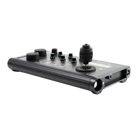
Front panel of the controller is equipped a joystick and two knobs to adjust:
SPEED and DAMPING. SPEED knob allows to adjust speed range, whereas
DAMPING knob regulates smooth acceleration and deceleration of movement,
ie. the user can adjust the time at which the drive reaches the desired speed
or stops. RJ-45 cable socket and power switch are located on the upper wall of
the controller housing. Joystick, placed in the centre of the front panel, enables
user friendly programming, controlling and conguration. Simple and functional
menu provides the ergonomics of operation. AIONTM IQ controller is equipped
with 1/4” mounting hole that allows to attach it to slider cart, for example, using
Slidekamera VARIOTM Magic arm 8” or 11”.
[1] Power switch
[2] RJ-45 cable socket
[3] LCD display
[4] SPEED knob
[5] DAMPING knob
[6] Joystick
[7] 1/4” mounting hole
5
4
6
12 21
7
3

4
AIONTMIQ
2. How to operate the AIONTM IQ controller
After you switch the power on the startup screen will appear on LCD for about
1,5s.
2.1. Specifying startup parameters
After switching the power on it is necessary to determine the working mode of
the drive. We differentiate three types of modes:: AUTO, MAN i FREE.
AUTO - basic automatic calibration. The dirve automatically moves
to the reference point. Movement range corresponds to the one speci-
ed during the automatic calibration.
MAN - the user determines the reference points (hence the move-
ment range) by using the joystick and the SPEED knob.
FREE - this mode does not require setting any movement range.
Not recommended when working with XTMSLIDER.
2.1.1. AUTO (basic automatic calibration)
In case of AUTO working mode, after switching the power, a message will
appear on LCD screen:
Use the joystick to determine the direction of the movement so that the drive
can automatically set the reference points. As soon as the drive determines
the points there is a message on LCD that the drive is ready for work. After
pressing OK (understood as pressing the joystick) the main menu appears on
the screen.
2.1.2. MAN (manual calibration)
In case of MAN working mode, the controller moves to the manual calibration.
This mode allows to determine the reference points anywhere on XTMSLIDER
rail, not necessarily at the ends. This mode is recommended if you need to
determine a short range of motion for the cart.
Message on the screen requires the user to determine points of reference.
By moving the joystick right and left set the reference points for the drive. Use
SPEED knob to determine the speed of the cart, this will allow you to decce-
larate before the cart reaches second point of reference. Press the joystick to
accept.
Before the rst use of the drive
it is necessary to perform auto-
matic calibration of the driving
motor. This step is necessary
for the drive to function properly
and cannot be neglected. Auto-
matic calibration is performed
only before the rst use,
it determines the range of mo-
vement for your X
TM
SLIDER.
IMPORTANT!
AUTO Referencing
<- or -> to run
Driver ready
press OK
When setting points of reference
in MAN mode exercise extreme
caution so that the cart does not hit
the side feet of your X
TM
SLIDER.
IMPORTANT!
Set 1st RefPoint
<- -> & press OK
Set 2nd RefPoint
<- -> & press OK

5
AIONTMIQ
IMPORTANT!
When working with the drive in
FREE Mode exercise extreme cau-
tion.
Lack of reference points increases
the risk of the cart hitting the side
feet.
It may cause damage of the equip-
ment.
As soon as the user sets the reference points, a message on LCD appears
that the drive is ready for work. After pressing OK (understood as pressing the
joystick) the main menu appears on the screen.
2.1.3. FREE (no limits)
In case of FREE working mode, there are no limits as to the movement
range. FREE Mode does not require setting any reference points. The driver is
immediately ready to work.
2.2. Main menu
PAs soon as the startup parameters are determined the controller enters
a main menu with working programs and additional CONFIG menu. Navigate
by moving joystick up and down. Sign „ > < „ indicates selected choice.
Press the joystick to ented selected program. Main menu features four entries::
„VIDEO”, „ANIMATION”, „TIMELAPSE” and „CONFIG”.
2.2.1. Menu CONFIG
After entering [Info] there will be information about the voltage: Vin, and
range of motion for the cart determined during initial calibration L.
CONFIG menu has ve entries „[Info]”, „Power”, „Backlight” , „
[Calibration]” and „<Back>”. The list boxes in square brackets []
indicate functions generating own screen. In order to activate them, press the
joystick. At the end of each submenu there is „<Back>”. Pressing the joystick
in this eld results in returning to the main menu. The remaining elds of the
submenu are the parameters, next is the value of the parameter. To change the
value move the joystick right or left.
Power- driving motor power: In case of X-GEAR it is 100% with
not change possibility.
Back Light - adjusts the brightness of the LCD. By moving the
joystick left or right you can set the brightness within the range of: 10-
100%w zakresie od 10-100%
[Calibration] - driving motor automatic calibration described
in point 2.1.1 of the manual
<Back> - return to main menu
Driver ready
press OK
ANIMATION
> CONFIG <

6
AIONTMIQ
V”: means that the battery voltage is too low. Replace
the battery immediately in order to avoid to a sudden
stop of the drive, which may result in damage
to the equipment.
t”: (Thermal Warning) indicates temperature warning. Turn off the
drive immediately so as not to overheat the driving motor.
T”: (Thermal Shutdown) indicates emergency drive shutdown due
to overheating. You should immediately turn off the drive and wait
until FAULT light switches off.
2.2.1.1. Driving motor automatic calibration
Please note that automatic calibration is only possible when working with the
slider. After selecting [Calibration] from „CONFIG” menu a message
appears on LCD:
Use the joystick to determine the direction of the movement so that the drive
can automatically set the reference points.
After the automatic calibration is performed there will be a message on the
screen displaying the length of motion range for the cart for your XTMSLIDER.
After the power is turned off the information is stored in the controller
so there is no need to repeat the procedure until you mount the drive on
a slider of a different length.
2.2.2. VIDEO
As you enter VIDEO program, a submenu will appear on the screen with dif-
ferent operating modes:: [Free Ride], [Recording], [Play-
back], [VideoLoop] ,<Back>.”
If the backlight of the LCD screen
starts ashing and there wil be an
orange ashing light under FAULT
marking on the right socket of the
driving motor, the user is informed
about existing error. In such situ-
ation, immediately enter
CONFIG menu →
[Info]. Information about the
error should appear in the upper
right corner of the screen.
IMPORTANT!
CALIBRATION
<- or -> to run
CALIBRATION
in progress
Vin=9.8V V
L 1276.1mm
CALIBRATION
L 1276.1mm
> VIDEO <
TIMELAPSE

7
AIONTMIQ
2.2.2.1. Free Ride
Free Ride mode allows the user to control the speed of the cart using joystick
and adjusting knobs. SPEED knob sets the maximum speed desired by the
user. DAMPING knob is used to determine the time at which the drive reaches
the desired speed or stops, what allows to achieve very smooth acceleration
and deceleration of the cart. By moving the joystick right or left you can control
the level of acceleration/deceleration of the cart. Pressing the joystick causes
the driving motor to stop immediately and the centroller returns to VIDEO menu.
Current position of the cart, measured in mm [1]
Maximum speed of the cart set by the user [2]
Currently set speed [3]
Acceleration / deceleration time [4]
When you work in Free Ride mode you can change SPEED and DAMPING
parameters at any time during the movement. SPEED knob allows to set the
speed value within the range of 2 -200mm/s. DAMPING knob allows to set
the acceleration/deceleration time within the range from 0.1s to 10s. Sample
screen presented above informs that the maximum speed of the cart is set on
200mm /s [2] , the currently set speed of the cart is 169mm/s [3].The value is
1.2 [4] , means that the maximum speed will be achieved after 1.2 seconds.
Please note that depending on the chosen method of calibration the current
position of the cart is measured and presented on the screen in a different way.
The table below illustrates and explains the messages on the controller. The
table refers to all modes and programs unless it is indicated otherwise in the
manual.
The positioning of the cart for different calibration methods.
Selecting AUTO or MAN for a calibration method, please note that the position
of „0” means the left extreme point of reference. The value grows as the cart
moves closer to the right extreme point of reference.
The direction of movement is indicated with currently set speed value. If the
currently set speed is in the opposite direction it is marked with the sign „-”.
FreeRide 1100.1
200 169 1.2
1
2 4
3
FreeRide 1100.1
200 -169 1.2
AUTO/MAN

8
AIONTMIQ
Selecting FREE Mode the user does not determine any reference points, the-
refore the position at which the cart stands at that moment is marked as „0”
(starting point). From that starting point, any position to the left is determined
as a negative number whereas any position to the right, as a positive number.
The direction of movement is indicated with currently set speed value. If the
currently set speed is in the opposite direction it is marked with the sign „-”.
2.2.2.2. Recording
Recording mode is designed to record the movements of cart in order to play
it back later in Playback mode. Movement control (SPEED and DAMPING) is
exactly the same as in Free Ride mode, so the user can change SPEED and
DAMPING parameters at any time during the movement. In order to nish the
recording and return to the menu press the joystick. The controller can store 59
seconds of the recording. Recorded movement is stored in the controller until
the power supply is switched off.
Current position of the cart, measured in mm [1]
Maximum speed of the cart set by the user [2]
Currently set speed [3]
Acceleration / deceleration time [4]
If length of the recorded movement exceeds 59 seconds, a message on the
screen will appear informing the user that the controller memory is full.
To stop the recording before the end of 59 seconds, press the joystick. In or-
der to play back the recorded movement, return to the main menu and enter
Playback mode.
2.2.2.3. Playback
Playback pmode plays back movements of the cart saved in Recording mode.
Once you enter Playback mode the screen displays information about the
length of the recording or the lack of it.
FreeRide -271.9
90 -40 1.2
FREE Mode
FreeRide 1100.1
200 169 1.2
1
2 4
3
Video Rec 668.7
Memory Full

9
AIONTMIQ
[Recording]
> [Playback] 59s
Playback 0.0
No Records
When you select [Playback] there will be a message displayed on the screen:
Go Home?”. The controller requires the user decision whether the
cart should return to the position where the recording of movement started
(-> Y) or whether to start playing back the movement from the current position
of the cart (N <-). Select the option by moving the joystick in the appropriate
direction. You can return to VIDEO menu at any time by pressing the joystick.
The controller displays information about the current position of the cart [1] and
the current/ overall time of the recording [2]. As the recorded movement
stops press the joystick to return to VIDEO menu..
2.2.2.4. Video Loop
During VideoLoop mode the cart moves from one reference point to the other
without stop. It automatically turns back and starts moving in the opposite direc-
tion once it reaches the end of the movement range. There is no need for the
user to determine the direction of the movement. The user can change SPEED
and DAMPING parameters at any time during the movement. SPEED knob
allows to set the speed value of the cart [1]. DAMPING knob allows to set
the acceleration/deceleration time [2]. Pressing the joystick causes the driving
motor to stop immediately and the centroller returns to VIDEO menu. W In Vi-
deoLoop mode there is no „-” sign when the cart moves in the opposite
direction.
Current ly set speed of the cart [1]
Acceleration/deceleration time [2]
Playback 590.2
Go Home? N<- ->Y
Playback 7267.4
press OK to Play
Playback 722.1
Time: 7/59s
Playback 58.4
press OK to exit
1
2
VidLoop 856.6
36 3.1
12
IMPORTANT!
If you selected FREE Mode when
setting startup parameters it is im-
portant to remember that the drive
has no reference points set. Con-
sequently, it will move only in one
direction and will not turn back. Use
SPEED knob to adjust the speed of
the cart paying special attention so
it does not hit side feet of the slider.

10
AIONTMIQ
2.2.3. TIMELAPSE
TIMELAPSE program is designed for interval shots synchronized with the mo-
vement of the cart (Motion Timelapse). Shutter release cable connected to the
socket on driving motor enables to synchronize the drive with the camera. After
entering TIMELAPSE program the user has to set the parameters below::
Mode – Continuous / SDS working mode
Direction – cart movement direction: left/right
Interval – time at which the drive takes a shot (1-600s)
Expos. – duration time of the trigger signal (from 0.1 to 99.9 s)
Shots – number of photos to take during the track (from 10 to 30
thousand). Time of the track is calculated automatically by the contro-
ller. It can be determined from the formula: Interval x Shots
[Start] – TIMELAPSE program starts
<Back> – controller returns to main menu
In Continuous mode, the cart moves smoothly with a constant speed. In this
case, there is no need to use the cable release attached to the driving motor
(especially for short exposure times). The release time can be successfully set
on the camera, or in the cable release with the interval function.
In SDS mode (Shot Drive Shot) the cart moves in steps between the points
where you want to take photos.
The trigger signal, with a preset duration time (Expos.) is given to the next point
before the cart moves. Shutter release cable connected to the socket on driving
motor enables to synchronize the drive with the camera.
The distance that the drive covers during the track is calculated from the place
where the cart is currently located,
to the end of the range of movement in a set point direction (Direction).
If specied startup parameters were: AUTO or MAN the controller will cal-
culate automatically length of step for SDS mode and speed for Continuous
mode. However, in FREE mode, due to the fact that no reference points were
dened, after setting all parameters there would be an additional message on
the controller screen asking the user to manually determine the length of step:
1 – 999mm.
In case of Continuous mode, once you start TIMELAPSE mode (by selecting
[Start]), use SPEED knob to set the speed for the cart: 0.1 to 10 mm / s.
The sample screen presented below informs about the position of the cart on
the slider rail [1]. There are 10 min left until the end of the track [2]. The drive
has already taken eight photos out of two hundred and fty photos set by the
user [3]. The user can stop the program at any time by pressing the joystick
for 2 seconds. When the drive has taken all the photos and stops the program
there will be a message on the screen: Timelaps end OK to exit. Press the
joystick to return to the main menu.
Please note that it is important to
select a proper direction of the
movement in TIMELAPSE program.
If you choose movement direction
as left and the cart will be located in
the left reference point „ 0”,
the device will encounter resistance
as it is the end of its movement
range. Consequently, the drive will
not move.
IMPORTANT!
he controller will set the maximum
length of step for the drive depen-
ding on the time that is has for the
movement (it is calculated from the
formula: Interval-Exposure).
IMPORTANT!

11
AIONTMIQ
71.1 0h10min
Shot: 8/250
21
3
ANIM dirR
Go Home? N<- ->Y
ACurrent position of the cart [1]
Time remaining to the end of the track [2]
Number of currently taken shots /number of shots to capture [3]
2.2.4 ANIMATION
ANIMATION allows to program track of the cart during which the drive take
series of photos (the drive will trigger the shutter release itself through a cable
connected to the camera). After entering ANIMATION program set the indivi-
dual parameters:
Direction – direction in which the cart moves: right/ left
HomePos – home position (measured in mm). Position determi-
ned by the user from which the drive should start its work. Home
position can be determined in any place on the rail (within the range
of calibration)
Step – length of step (measured in mm)
Steps – number of steps. Controller calculates the maximum
amount of steps basing on home position (HomePos) and selected
direction of movement.
Shots – number of shots to take after the cart stops
Delay – time of the delay. Time after the cart stops before the drive
triggers the shutter (0-9s)
[Start] – ANIMATION program starts
<Back> – controller returns to main menu
When you select [Start] in ANIMATION program there will be a mes-
sage displayed on the screen: „Go Home?”. The controller requires the
user decision whether the cart should start the movement from determined
HomePos (-> Y) or whether to start the movement from the current position
of the cart (N <-). Select the option by moving the joystick in the appropriate
direction. DirR on the screen indicates the selected direction of the movement,
in that particular example: right. You can return to the main menu at any time
by pressing the joystick.
IMPORTANT!
Please note that it is important
to select a proper directionof the
movement in ANIMATION
program. If you choose movement
direction as left and the cart will be
located in the left
reference point „ 0”, the device will
encounter resistance as it is the
end of its movement range.
Consequently, the drive will not
move.

12
AIONTMIQ
After the user determines the desired starting position, information about cur-
rent parameters will appear on the LCD. In order to start, move the joystick in
a direction you selected earlier. After the rst step, move the joystick again to
initiate another steps. The user can freely move a step forward or backward (by
moving the joystick right or left) or skip a few steps forward or backward (by
holding the joystick longer in a selected direction).
Selected movement direction [1]
Current position of the cart [2]
Current step/ number of programed steps [3]
Length of step [4]
Number of shots already taken / number of all shots to take [5]
Sample screen presented above informs that the user selected right as move-
ment direction [1]. If the user chose left, there would be: dirL- on the screen.
Current position of the cart is 80mm [2] from the left reference point in AUTO
or MAN mode, or starting point in FREE Mode. Length of step set by the user
is 40mm [4]. The drive currently performs second step out if thirty steps set
[3]. The drive has already taken three shots out of ve shots set [5].The user
can stop the program at any time by pressing the joystick. When the drive has
taken all the photos and stops the program there will be a message on the
screen with the current position of the cart. Press the joystick to return to the
main menu.
ANIM dirR 80.0
2/30 40.0 3/5
21
34 5
ANIM dirR 327.0
press OK. to exit

13
AIONTMIQ
IMPORTANT INFORMATION FOR CORRECT DISPOSAL OF THE PRO-
DUCT IN ACCORDANCE WITH EC DIRECTIVE 2002/96/EC
At the end of its working life, the product must not be disposed
of as urban waste. It must be taken to a special local authority
differentiated waste collection centre or to a dealer providing this
service. Disposing
of electronic equipment separately avoids possible negative con-
sequences for the environment and health deriving from inappropriate dispo-
sal and enables the constituent materials to be recovered to obtain signicant
savings in energy and resources. As a reminder of the obligation to dispose
of electronic equipment separately, the product is marked with a crossed-out
wheeled dustbin.
All Slidekamera products are covered manufacturer’s warranty for a period
of 12 months from the date of sale. Warranty covers any design faults or of
the material of the product which resulted in the product malfunctioning. The
warranty covers the repair, or, if the repair proves impossible, replacement of
the product with a new one. Hovewer, the cost of repair of the product cannot
overrun the catalogue value of the product. The warranty does not cover
damage and / or product defects resulting from the improper usage, as well as
not following product maintenance specications.
The warranty excludes:
• unauthorized attempts to repair or modify
• mechanical damage caused during transport and operation of such
features as scratches, dents, pits, dirt, etc ...
• ooding, moisture
To obtain warranty service the purchaser should deliver the damaged product
together with a proof of purchase and proof of payment (invoice, cash register
receipt). The product will be accepted for warranty service on condition that it
is delivered with correctly lled in complaint form and properly protected during
transport. You can download the complaint from: www.slidekamera.com.
After the warranty period is exceeded any spare parts can be purchased
directly from the manufacturer or in any selected points of sale.
3. Terms of warranty IMPORTANT!
PLEASE NOTE: Any package sent
at the expense of HET-CNC s.c.,
80-175 Gdańsk, Ul. Kartuska 386
will not be received

Table of contents
Other Slide Kamera Controllers manuals
Popular Controllers manuals by other brands

ZyXEL Communications
ZyXEL Communications NXC2500 quick start guide

Rice Lake
Rice Lake iRite 920i installation manual

Dometic
Dometic Go Power GP-PWM-10-SQ user manual

Elan
Elan EL-SC-100 Quick install guide

Grundfos
Grundfos LC 231 Installation and operating instructions

meitav-tec
meitav-tec PYROCON12-TRACE owner's manual