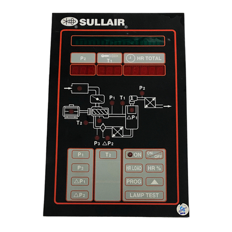
Sullair SUPERVISOR II Series User manual

SUPERVISOR
II
and
SUPERVISOR
CONTROLLER™
SEQUENCING & PROTOCOL
MANUAL
OPERATOR’S
MANUAL AND
PARTS LIST
KEEP FOR
FUTURE
REFERENCE
Part Number 02250139-197
©Sullair Corporation

AIR CARE
SEMINAR TRAINING
Sullair Air Care Seminars are 3-day courses that provide hands-on instruction in the proper operation, mainte-
nance and service of Sullair equipment. Individual seminars on Industrial compressors and compressor electrical
systems are presented at regular intervals throughout the year at a dedicated training facility at Sullair’s corporate
headquarters in Michigan City, Indiana.
Instruction includes discussion of the function and installation of Sullair service parts, troubleshooting of the most
common problems, and actual equipment operation. The seminars are recommended for maintenance and serv-
ice personnel.
For detailed course outlines, schedule and cost information contact:
Sullair Corporate Training Department
1-800-SULLAIR or 219-879-5451 (ext. 5630)
www.sullair.com/training.shtm
- Or Write -
Sullair Corporation
3700 E. Michigan Blvd.
Michigan City, IN 46360
Attn: Service Training Department

TABLE OF CONTENTS
Section 1 PAGE
SUPERVISOR
PROTOCOL 1SECTION 1.1 SUPERVISOR II PROTOCOL
VER 3.0
2BROADCAST MODE OFFERS SEVERAL
ADVANTAGES:
2MESSAGE FORMAT
3MESSAGE TYPES
3RUN STATUS (r)
3MODE (m)
6ANALOG SHUTDOWN TABLE
6RS-485 SERIAL CHANNEL
7TIME SLICING OF THE RS-485 SERIAL
CHANNEL
Section 2
SUPERVISOR II
SEQUENCING 9Modes of Sequencing
9Remote Control Mode or Digital Inputs For Remote
Sequencing
10 Description of Typical Compressor System in Sullair
Sequencing Mode
10 MACHINE PREPARATION PRIOR TO
SEQUENCING
10 SYSTEM OPERATION
11 System Setup and Tuning
12 Changing Sequence Parameters
13 SYSTEM DISPLAY
14 REMOVING A MACHINE FROM SEQUENCE
FOR MAINTENANCE
14 CALIBRATION OF P2 PRESSURE
TRANSDUCERS
14 NETWORK WIRING
OPERATOR IS REQUIRED TO READ
ENTIRE INSTRUCTION MANUAL

TABLE OF CONTENTS
Section 2
SUPERVISOR II
SEQUENCING
(CONTINUED) 15 COMMON HEADER
15 FULL LOAD FEATURE
Section 3
SUPERVISOR
CONTROLLER
SEQUENCING 17 Philosophy of Sequencing
17 Modes of Sequencing
17 Remote Enable/Disable Keypad Feature
17 Remote Control Mode or Digital Inputs For
Remote Sequencing
18 Description of Typical Compressor System in
Sullair Sequence Mode
18 MACHINE PREPARATION PRIOR TO
SEQUENCING
18 SYSTEM OPERATION
19 System Setup and Tuning
20 Changing Sequence Parameters
21 SYSTEM DISPLAY
22 REMOVING A MACHINE FROM
SEQUENCING FOR MAINTENANCE
22 CALIBRATION OF P2 PRESSURE
TRANSDUCERS
23 NETWORK WIRING
23 COMMON HEADER
23 FULL LOAD FEATURE
Section 4
VARIABLE SPEED
DRIVE 25 VARIABLE SPEED DRIVE APPLICATIONS
25 I. SETUP FOR FIXED-SPEED MACHINES
NETWORKED TO A VSD MACHINE
25 SETUP FOR VSD MACHINE

Section 4
VARIABLE SPEED
DRIVE (CONT.) 25 SEQUENCING WITHOUT AUTO ROTATION
OF FIXED-SPEED MACHINES
26 SYSTEM SETUP WITH ONE VSD COMPRESSOR
AND OTHER FIXED-SPEED COMPRESSORS
26 II. SYSTEM SETUP WITH ONLY VSD
COMPRESSORS
Section 5
SEQUENCING
TIMERS 27 Recovery Time & Delayed Start Timer
28 Example 1: Recovery Timer- Unload
Operation Example
29 Example 2: Recovery Timer- Load
Operation Example
30 Example 3: Recover Timer- Starting Example
(pressure drops below Lowest Pressure setting)
31 Example 4: Delay Start Timer- Pressure below
Sequencing Load pressure but above Lowest Pressure
32 Summary
TABLE OF CONTENTS

NOTES

Section 1
SUPERVISOR PROTOCOL
1
SECTION 1.1 SUPERVISOR II PROTOCOL VER 3.0
This document describes features that are more technical in nature than the normal opera-
tion of the machine, in particular sequencing and communication.
The Supervisor II communications link is a RS-485 (two wire) serial line. The following three
parameters must be set correctly to be able to communicate through this link.
COM ID# Unique number for each machine on the link.
BAUDRATE Must be the same for all machines (default is 9600).
SEQUENCE Sequencing mode (see below).
The function of the link is specified by the setting of the Sequence parameter as follows :
DISABLED Responds to status and parameter change messages but will not
respond to messages to start, stop, load or unload.
REMOTE Responds to status and parameter change message but will not
respond to messages to start, stop, load or unload. The remote inputs
and outputs are enabled (start/stop, load/unload, master/local).
SLAVE Will respond to all messages, but will not start or load unless com-
manded to do so by a message. This mode is used to control the
machine from a master computer.
HOURS Sends net status message about once a second, starts, loads and
unloads machines based on sequencing hours.
COM ID# Sends net status message about once a second, starts, loads and
unloads machines based on machine Com ID#.
If the sequence parameter is set to Hours or Com ID# then the following parameters must
be set (see section on Sequencing Methods) :
LAST COM Highest Com ID#
LOWEST Lowest line pressure before starting machine.
RECOVER Recovery time.
ROTATE Machine rotation time.
CAPACITY Capacity of the machine.
SEQ HRS Sequencing hours.
See Sequencing (Section 2) for detailed descriptions of sequencing parameters and operation.
Messages can be sent between Supervisor II controls and to/from a computer. There are two
modes of operation, query and broadcast.
If the sequence parameter is set to DISABLED, REMOTE, or SLAVE then the query mode
is enabled. The Supervisors will only send messages in response to a message from the
host computer. In DISABLED and REMOTE the Supervisor controls the machine locally (ie.
start, stop load, and unload) and will ignore any messages to start, stop, load or unload.
Only status and parameter change messages will be acted on. In SLAVE mode the

Section 1
SUPERVISOR PROTOCOL
2
Supervisor will not start, stop, load or unload unless a message commands the action.
If the sequence parameter is set to HOURS or COM ID# then the broadcast mode is
enabled. In this mode the machines send the net status message periodically.
Approximately once a second, all machines that are on line will send a net status message.
In this manner, each machine knows the status of every other machine. Sequencing deci-
sions are made individually by each machine based on the status of all on line machines in
the system. Collisions on the serial channel
are avoided by a time slice scheme (See section on Time Slice).
BROADCAST MODE OFFERS SEVERAL ADVANTAGES:
1. Because there is no master, the number of messages are cut in half (decreasing
response time). In master/slave mode the master must send a message to request sta-
tus and the machine must send a message back. In broadcast mode, each machine
sends it’s status approximatley once a second.
2. When a machine goes off line or on line there is no need to poll for a new master.
3. Individual machines may be taken off line or put on line with no effect on communications.
This is handy for maintenance or when a machine is to be controlled manually.When the
machine is stopped it still sends net status messages so other machines or a monitor can
display it’s status. When the machine is DISABLED it will not send net status messages
but will respond to status and parameter change messages.
4. Because decisions are made locally, the response of the system is very good, less than
one second for trimming, loading and unloading. One second plus starting time for a
machine to start.
5. There are no extra communications for monitoring. Since each machine sends it’s status
every second, the monitor does not need to send messages. However, the monitor may
send messages to get other status, change parameters or issue run commands (for
example a machine may be stopped from the monitor).
6. The monitor does not need to be continuously connected. A monitor may be connected
or disconnected at any time.
MESSAGE FORMAT
All messages will have the following format.
@ Start of text (2)
## Two character com number
m One character message type
d Zero to several data characters (values separated by comma’s)
xx Two character check sum
CR Carriage return (13)
LF Line feed (10)
For the following examples the STX, CR and LF will not be shown.
Message transmission format is 8-bit, 1-stop bit, no parity.

Section 1
SUPERVISOR PROTOCOL
3
MESSAGE TYPES
The following messages sent by the sequencing master to slaves:
MESSAGE TYPE FORMAT EXAMPLE
Q - Quick status ##Qxx 01Q4E
S - Stop ##Sxx 01S4C
U - Unload ##Uxx 01U4A
L - Load (Modulate) ##Lxx 01L53
F - Full load ##Fxx 01F59
T - Trim (Modulate) ##Txx 01T4B
E - Emergency Stop ##Exx 01E5A
If a machine is stopped U, L, F or T will start the machine.
The slave response to these messages is:
MESSAGE TYPE FORMAT EXAMPLE
q - Quick status ##q1,2,h,r,mxx 01q0,115,2000,M,C65
1 is Capacity, 2 is P2, h is Run Hours, r is Run Status and m is Mode
RUN STATUS (r)
E - E-Stop
M - Manual Stop m - Manual stop & Common Fault
R - Remote Stop r - Remote stop & Common Fault
B - Standby b - Standby & Common Fault
S - Starting s - Starting & Common Fault
U - Unloaded u - Unloaded & Common Fault
L - Loaded l - Loaded & Common Fault
T - Trim t - Trim & Common Fault
F - Full load f - Full load & Common Fault
MODE (m)
A - Auto run mode, remote start/stop enabled.
a - Auto run mode, remote start/stop disabled.
C - Cont run mode, remote start/stop enabled.
c - Cont run mode, remote start/stop disabled.
The following messages sent by machines when the system is in stand alone sequencing :
MESSAGE TYPE FORMAT EXAMPLE
N - Net status ##N1,2,h,r,mxx 01N0,115,2000,M,C88
M - Monitor Enable ##Mxx 01M52
1 is Capacity, 2 is P2, h is Run Hours, r is Run Status and m is Mode.

Section 1
SUPERVISOR PROTOCOL
4
The following messages are sent by the monitor:
MESSAGE TYPE FORMAT EXAMPLE
G - Get parameter ##Gn,xx 01G3,58
P - Change parameter ##Pn,v,xx 01P3,4,90
D - Display message ##Dxx 01D5B
I - Status info ##Ixx 01I56
A - Auto run mode ##Axx 01A5E
C - Cont run mode ##Cxx 01C5C
In the change parameter message n = number and v = value.
1 Machine type (read only)
2 Machine options (read only)
3 Language (0=French, 1=German, 2=Italian, 3=Spanish, 4=English)
4 Units (0=Metric, 1=English)
5 Unload pressure
6 Load pressure
7 P1 Max pressure
8 Off load time (0-15 min.)
9 Wye-Delta time (0-10 sec.)
10 Drain interval time (0-30 min.)
11 Drain time (0-10 sec.)
12 Restart time (0-60 sec.)
20 Machines (1 - 8)
21 Sequence method (0-Disabled, 1-Remote,
2-Slave, 3-Hours, 4-Com ID)
22 Sequence hours (0-30,000)
23 Lowest pressure
24 Recover time (2-30 sec,)
25 Capacity (0-10,000)
26 Rotate Time (10-250 hrs.)
40 T1 CAL (-7 to +7)
41 T2 CAL (-7 to +7)
42 T3 CAL (-7 to +7)
43 T4 CAL (-7 to +7)
44 T5 CAL (-7 to +7)
45 T6 CAL (-7 to +7)

Section 1
SUPERVISOR PROTOCOL
5
(Continued from page 4)
46 T6 CAL (-7 to +7)
47 P2 CAL (-7 to +7)
48 P3 CAL (-7 to +7)
49 P4 CAL (-7 to +7)
50 dP1 CAL(-20 to +10)
51 P3 MAX (-7 to +7)
70 Parameter Protection
(0 = NOT Protected, 1 = Protected)
71 Shutdown on warning
(0 = Warning, 1 = Shutdown)
Parameter protection inhibits the changing of any parameters via the Supervisor keyboard.
This protection can only be enabled and disabled through the serial channel.
The shutdown on warning feature shuts the machine down on alarms that normally only
display a message. This feature can only be enabled and disabled through the serial chan-
nel.
The slave response to the above messages is:
MESSAGE TYPE FORMAT EXAMPLE
p - Parameter changed ##pn,v,xx 01p5,1003D
g - Parameter status ##gn,v,xx 01p5,1003d
d - Display message ##dm,mxx 01d E-STOP, 0 72DE
i - Status info ##id,....,ddxx
q - Quick status ##q1,2,h,r,mxx 01q0,0,E,C66
The parameter changed message sends the value of the parameter back after the change
was attempted. It may not have been changed if it was out of legal range.
Status info message sends the status in the following order:
11. Analog shut/down
12. Digital outputs (BIT 0=K1, BIT 1 =K2, ETC.)
13. Digital shut/down (BIT 0=D1, BIT 1=D2, ETC.)
14. Digital inputs (BIT 0=D1, BIT 1=D2, ETC.)
15. Run Time
16. Load Time
17. Run Status
18. Mode
1. P1
2. P2
3. P3
4. P4
5. T1
6. T2
7. T3
8. T4
9. T5
10. T6

Section 1
SUPERVISOR PROTOCOL
6
ANALOG SHUTDOWN TABLE
RS-485 SERIAL CHANNEL
The RS-485 is a party line type channel, ie. any device on the channel may transmit or
receive on the same wires. The transmitters and receivers are differential type that use two
wires and a ground. These have very good noise immunity because the receiver measures
the voltage between two signals, and not between a signal and ground (as RS-232 does).
If noise occurs on both lines it will be rejected by the receiver. The ground is used to keep
the receiver from floating too high above the transmitter.
A one is transmitted as 5 volts on the + line and 0 volts on the - line. A zero is 0 volts on the
+ line and 5 volts on the - line.
The transmitters are tri-state, meaning they can drive the transmission line to a one (5
volts), zero (0 volts) or be turned off (high impedance). All transmitters except one must be
in tri-state mode, otherwise the transmission will be garbled and damage to the transmitters
can occur.
1 = P1
2 = P2
3 = P3
4 = P4
5 = dP1
6 =dP2
7 = dP3
8 = T1
9 = T2
10 = T3
11 = T4
12 = T5
13 = T6
Transmitter Receiver
+
-
+
-
Up to 4000’
GND GND
+ line
- line
Receiver
+5v
0v
+5v
0v
1
0

Section 1
SUPERVISOR PROTOCOL
7
TIME SLICING OF THE RS-485 SERIAL CHANNEL
When the sequencing mode is set to HOURS or COM ID# the machines will broadcast their
status (net status message) about once a second. To keep machines from sending mes-
sages simultaneously, time is sliced into periods (up to 9 maximum), one for each machine
and one for a monitor. A machine will only send a net status messages during it’s time slice
(see table below).
Time Slot COM ID# Time out
0 Monitor .5 sec
1 1 .125 sec
2 2 .125 sec
3 3 .125 sec
4 4 .125 sec
5 5 .125 sec
6 6 .125 sec
7 7 .125 sec
8 8 .125 sec
The number of time slots is determined by the LAST COM parameter. If the LAST COM
parameter is set to 4 then there will be 5 time slots (0 through 4). One for each machine and
one for the monitor.
The time slot for a monitor is longer because it may not be able to respond as quickly to a
message as the Supervisors.
The Supervisors establish what the current time slot is by either receiving messages or tim-
ing out. Any net status message establishes the time slot because the senders COM ID# is
imbedded in the message. For example if a net message from machine 2 is received then
time slot 2 has just finished and 3 is started.
If there is no message for a time out period (see table above) then it is assumed that the
machine assigned to that time slot is off line and the next time slot starts.
A machine sends a net status message immediately after a message is received from the
next previous machine, or that machines time slot has expired. For example if the time slot
has been established as 2 and either machine 2 sends a net status message or no mes-
sage is sent within .125 seconds, then machine 3 will send a net status message (if on line).
During time slot 0 a monitor may send a message, typically a status request or parameter
change message. A message that is sent by the monitor may need a response from one of
the machines. This response must come before the time out period (.5 sec).
Consider the following system with 4 machines with no monitor and machine 3 is off line.
Time Slot COM ID# Status Action
0 Monitor Off line .5 sec time out
1 1 On line Machine 1 net message
2 2 On line Machine 2 net message
3 3 Off line .125 sec time out
4 4 On line Machine 4 net message

Section 1
SUPERVISOR PROTOCOL
8
Let’s start this example at time slot 1. Machine 1 sends a net message. Machine 2 receives
the message and establishes the time slot as 2. Machine 2 immediately sends it’s net sta-
tus message establishing the slot at 3. Since machine 3 is off line no message will be sent
and after .125 sec. the time slot will rotate to 4. Machine 4 will send it’s net status message,
and the time slot will roll over to slot 0. Since there is no monitor, after .5 sec. the time slot
will rotate to 1 and machine 1 will send it’s net status message. This cycle will repeat until
other machines go off or on line. When a machine is switched on line or powered up it does
not know what the time slot is until it receives a net message from another machine. If only
one machine is put on line, or multiple machines are powered up at the same time, none of
them will know what the current time slot is. To overcome this deadlock the following
scheme is used.
When a machine comes on line it waits for an initial timeout period of 1.5 seconds times it’s
COM ID#. For example if it’s COM ID# is 4 then it will wait 6 seconds. If a message is
received during the initial timeout period then the time slot will be known because the
senders COM ID# is imbedded in the message. For example if a net message from machine
2 is received then the time slot is 2.
If no messages are received within the initial timeout period then a net message is sent. It
can be assumed that either there are no other machines on line or that they have been put
on line at the same time and are waiting for their initial timeout to expire. This keeps sever-
al machines that are powered up at the same time from all sending net status messages
simultaneously.

Section 2
SUPERVISOR II SEQUENCING
9
Modes of Sequencing
REMOTE - Enables three digital inputs for Remote Start/Stop, Unload/Load and Master
Control. These inputs are normally controlled by remote relay contacts or a PLC controller.
A customer may then interface with custom sequencing panels which provide signals for a
2-wire stop/start operation.
SLAVE - Not to be used
SEQUENCE HOURS - In this mode machines are started and loaded depending on the
SEQUENCE HOURS parameter. The sequence hours parameter is similar to run hours
except that it can be changed. Digital inputs for Remote control are disabled. ROTATE
hours are disabled.
COM NUM - In this mode machines are started and loaded depending on the COMMUNI-
CATION NUMBER parameter. Operation is exactly the same as the SEQUENCE HOURS
method (see above) except the communications number is used to determine machine
sequence instead of sequence hours. Digital inputs for Remote control are disabled.
SEQUENCE HOURS with ROTATE Hours Enabled - A special version of SEQUENCE
hours for balancing run hours for use in only two-machine applications that has a demand
for only one machine. DO NOT use with more than two machines (See ROTATE hours
parameter setting for more information). Digital inputs for remote control are disabled.
Remote Control Mode or Digital Inputs For Remote Sequencing
There are three inputs and one output that are enabled in this mode:
Remote Start/Stop Input (D10)
Remote Load/Unload Input (D9)
Local/Master Input (D8)
Local/Master Output (K6)
Inputs D8, D9 and D10 are wired through customer furnished relay contacts to ground
(Supervisor II Common J3-20).
If D10CR is closed the machine will be enabled to start, if D10CR is open the machine will
stop, and be held stopped. If remote start/stop is not needed then jumper D10 (J3-19) to
GND (J3-20).
D10CR
D9CR
D8CR
GND J3-20
D10 J3-19 (Remote Start/Stop input)
D9 J3-18 (Remote Load/Unload input)
D8 J3-17 (Local/Master input)

Section 2
SUPERVISOR II SEQUENCING
10
The following table describes how the other inputs work:
Local/Master Load/Unload Operation
Open Open Normal load and unload
Open Closed Force unload
Closed Open Force load, unload at P1 max - 3
Closed Closed Force unload
The Local/Master Output is on when the Local/Master Input is on and the machine is not in
E-stop or Stop. If the Local/Master output is on the display will have two stars (**) in the mid-
dle of the bottom line. The Local/Master Output is a relay contact that can handle 110VAC
at 6 amperes. (J1-14 & J1-15)
Description of Typical Compressor System in Sullair Sequence Mode
MACHINE PREPARATION PRIOR TO SEQUENCING
1. Complete all machine startup procedures for stand-alone operation for the machines that
are to be sequenced together per the compressor operators manual.
2. Relocate the P2 signal for all machines to read the common header pressure. To recal-
ibrate the P2 signal for each machine so that they match within 1psi of each other, use
the system display mode described later to view P2 on all machines. Recalibrate P2 on
each machine to match P2 on the other machines.
3. Program each machine with a different COM ID number (i.e.1, 2, 3, etc.).
4. Set UNLOAD psi, LOAD psi, BAUD RATE, SEQUENCE mode (COM ID or HOURS),
LAST COM, LOWEST and RECOVER time (normally set at 10) the same for each
machine. Leave ROTATE hours disabled except for the specific application described
elsewhere; ignore the CAPACITY entry. Set all SEQ HRS the same unless it is desired
to force certain machines to initially run more than others in the HOURS mode.
5. Set the machines to run in AUTO mode. Machines will start immediately if the P2 sys-
tem pressure is low. On a fully pressurized system the machines will go into SEQ STOP
until a demand is seen. The following operation describes how machines are started,
fully loaded and unloaded by the sequencing mode selected. The AUTO mode provides
the means for each machine to SEQ STOP by timing out on its unload timer (UNLD TIM)
when the sequencing order decides the machine is to be unloaded.
SYSTEM OPERATION
For this example three machines are in a system with the load pressure set at 100, unload
at 110 psig (7.6 bar), lowest pressure at 90 psig (6.2 bar), and Recovery Time at 10 sec-
onds (default value). All machines are in sequence stop (top line of the display is SEQ
STOP). When the pressure drops below 102 psig (7.6 bar) a timer starts counting down from
120 seconds, if the pressure continues to drop the timer will count down faster. When the
timer expires or the pressure drops below 90 psig (6.2 bar) the first machine is started. If the
pressure does not go above 90 psig (6.2 bar) for 10 seconds (Recovery Time) the next
machine will start and so on until all machines are started.
As machines are started and loaded, there will be only one machine that is modulating, the

Section 2
SUPERVISOR II SEQUENCING
11
others will be forced to "FULL LOAD". The modulating (trim) machine will load at 2psig (.14
bar) above the load pressure parameter, 102 psig (7.03 bar) in this example, and unload at
2 psig (.14 bar) below unload pressure parameter, 108 psig (7.4 bar) in this example. The
reason for this narrower load/unload band is to keep all machines from loading and unload-
ing at the same time. The trim machine will be identified on the display as "TRIM" operat-
ing state. If the pressure rises above the unload pressure -2 psig (.14 bar)(108 psig (7.4
bar)) the trim machine will unload (display will say "UNLOADED") and the next machine in
the sequence will switch from full load to trim. If after Recovery Time the pressure is still
above 108 psig (7.4 bar) then the trim machine will unload and so on until all machines are
unloaded. Then if the pressure falls below load pressure + 2 psig (.14 bar) or 102 psig
(7.03 bar) the first machine in the sequence will load and be the trim machine. If after the
Recovery Time the pressure is still below 102 psig (7.03 bar) then the trim machine will go
to full load and the next machine in the sequence will load and become the trim machine.
System Setup and Tuning
The following shows the settings for a system of low pressure 100-110 psig (6.9 to 7.6 bar)
machines. The Trim High & Low Setpoints are not settable parameters, they are calculated
from the Unload and Load pressures. The Trim High Setpoint is 2 PSI (.14 bar) below the
Unload pressure and the Trim Low Setpoint is 2 PSI (.14bar) above the Load pressure.
100 psig (6.9 bar) Unload
98 psig (6.8 bar) Trim High Setpoint (calculated parameter)
92 psig (6.3 bar) Trim Low Setpoint (calculated parameter)
90 psig (6.2 bar) Load
85 psig (5.9 bar) Lowest pressure
10 Recover time (seconds)
Note that the unload pressure is set to 100 psi (6.9 bar) and not 110 psi (7.6 bar) as is nor-
mal on a stand alone machine. A stand alone machine set up at 100 psi (6.9 bar) to 110 psi
(7.6 bar) , starts to modulate above 100 psi (6.9 bar) and the horsepower is reduced.
However in a system a machine may be forced to full load, which would draw more than the
rated horsepower above 100 psi (6.9 bar). Therefore the modulation band of machines in a
system should be set up to be 10 psi (.7 bar) lower than their rated pressure.
For energy efficiency reasons it is desirable to have all running machines either at full load
or unloaded except for the one that will hereafter be called the trim machine. The trim
machine unloads when the line pressure rises above the Trim High setpoint.
The Trim High and Low setpoints are necessary because the trim machine must unload
before the fully loaded machines and load before the unloaded machines, otherwise all
machine would load and unload at the same time.
The LOWEST pressure parameter specifies the lowest pressure allowed before immedi-
ately starting a machine. A machine may also be started if the line pressure drops below the
Trim Low setpoint for a period of time.
The RECOVER time is used to keep multiple machines from loading, unloading or starting
at the same time. A timer is reset when a machine loads, unloads or loads after a start.

Section 2
SUPERVISOR II SEQUENCING
12
Decisions to load, unload or start another machine are deferred until the timer reaches the
RECOVER time setpoint. Note that the timer starts when a machine is added or taken away
from the system. If the pressure recovers within the RECOVER time, and then at a later time
the pressure drops below the Trim Low setpoint, another machine will load immediately. The
shorter the recovery time the more responsive the system to load changes, but the less
energy efficient it is because machines may not shut off as often. The more often a machine
loads the less likely it is to stay unloaded and shut off after the Unload timer expires. The
RECOVER TIME has a default value of 10 sec. and may be adjusted from 2 to 59 sec.
In the following discussion 'highest' refers to the machine with the highest SEQ HRS or
COM ID and 'lowest' refers to the machine with the lowest SEQ HRS or COM ID.
The following rules are used to load. unload and start :
1. Only the highest loaded machine will trim; the rest will be forced to full load.
2. The trim machine will unload when the line pressure rises above the Trim High setpoint.
The next highest loaded machine will then become the trim machine. If pressure remains
above the Trim High setpoint, the new Trim machine will unload after Recovery Time
expires. This process will continue until only enough machines are running and loaded
to maintain proper system pressure.
3. The lowest unloaded machine will load (trim) when the line pressure drops below the Trim
Low setpoint. If the pressure remains below the Trim Low setpoint the next Unloaded or
Sequence Stopped machine will load or start after the Recovery Timer expires. This
process will continue until only enough machines are running and loaded to maintain
proper system pressure.
4. The lowest stopped machine will start when the line pressure drops below the Trim Low
set point, and after a variable time out period. This time out is dependent on how far the
line pressure is below the Trim Low set point. The farther below the set point the shorter
the time to start.
5. The lowest stopped machine will override the above variable time out feature and start
when the line pressure drops below the Lowest Pressure set point, and after the recov-
ery timer expires.
Changing Sequence Parameters
To change parameters, push the program key until the top line of the display identifies the
parameter to be changed. The up arrow and logo keys will increment the parameter value
the lamp test will decrement. To save the changed value the program key must be pushed.
The next parameter will then be displayed.
The following parameters may need to be changed for sequencing:
COM NUM - Must be unique for every machine in the system. If there are three machines
in a system, for example, they must be numbered 1, 2 and 3.
BAUD RATE - Serial communications baud rate, almost always set to 9600.
LAST COM - Set to total number of machines in a system.
LOWEST - This should be set to the lowest allowable pressure before a machine has to
start. Normally this is 5 to 10 psi (.3 to. 7 bar) below the load pressure. If the system pres-

Section 2
SUPERVISOR II SEQUENCING
13
sure drops below this limit then the machine with the lowest SEQ HRS or COM ID is start-
ed immediately. A machine will also start if the pressure is below the Trim Low Setpoint for
a period of time. The length of this time is 0 to 120 seconds depending on the pressure. The
closer the pressure is to LOWEST pressure the shorter the time. For example if the pres-
sure drops below the Trim Low Setpoint by 1psi (.07 bar), and stays there a machine will
start in 120 seconds. If the pressure drops near LOWEST PRESSURE then a machine will
start in just a few seconds.
RECOVER - Recovery time. This parameter adds a delay between subsequent start, load
and unload commands.
ROTATE - Rotate time for two-machine systems. There are some systems where the trim
machine never unloads or stops and the second machine is never required; specifically a
two-machine system where one machine runs all the time and the other is used only for
backup. The rotate parameter forces the trim machine to stop (allowing the other machine
to start). The trim machine will stop when its sequencing hours are more than a stopped
machine sequencing hours by the rotate hours value. WARNING - do not enable this mode
when the above situation is NOT true, because unexpected starts and stops may occur
when manually starting or stopping a machine in the sequence for maintenance.
For example, consider a two-machine system with SEQUENCING hours of 1000 and
ROTATE of 50 hours on each machine. If one machine is started and continuously loaded,
it will run until it's sequence hours are 1050 (50 hours more than the stopped machine) then
stop. The other machine will start and run until it's sequence hours are 1100 (50 more than
the stopped machine) then stop, and so the machine will rotate back and forth every 100
hours.
CAPACITY - Not a functional parameter
SEQ HRS - To change this parameter, push the program key until SEQ HRS is displayed
on the top line of the display. Pushing the logo key will increment by 1000 hours, the up
arrow key will increment by 100 hours and the lamp test key will decrement by 100 hours.
The number will roll over at 30,000 hours. To set the hours to a lower number it may be eas-
ier to push the logo key until the display reads 30,000, then hit the up arrow key, the display
will then go to 0.
SYSTEM DISPLAY
There is a system display that may be helpful for trouble-shooting, and calibration. While in
the main display, push the logo key followed by the display key. The top line of the display
should show the numbers 1 through the number of machines in the system (set by param-
eter LAST COM). The second line shows the status of each machine. If the status letter is
lower case then the machine has a fault or warning. The status letters are:
E E-Stop U Unloaded
M Manual stop B Standby
L Loaded F Full Load
T Trim (loaded and modulating) S Starting
R Remote or sequence stop

Section 2
SUPERVISOR II SEQUENCING
14
If the up arrow key is pushed the system line pressure is displayed. If the up arrow key is
pushed again the line pressure and run hours of the first machine is displayed, if the arrow
key is pushed again the second machine is displayed and so on. The lamp test key changes
to the previous display.
REMOVING A MACHINE FROM SEQUENCE FOR MAINTENANCE
Make sure that ROTATE HOURS is disabled for all machines.
To temporarily disable a machine from sequencing for maintenance, simply press the STOP
pad then depress the E-Stop Button, remove power to that machine and apply the appro-
priate Lockout/Tagout procedure. The rest of the networked machines will continue to
sequence properly. When restoring the machine to the network, simply restore power, pull
out the E-Stop, press STOP and then AUTO. If the sequencing parameters have not been
changed, the machine will sequence in at the appropriate time. By revising that machine's
SEQUENCE HOURS before enabling sequencing, one may force it to move up or down in
the start priority in the HOURS sequencing mode.
To permanently remove a machine from sequence, reprogram the other compressors as
though the downed machine/s is/are not there. (Relocate the COM NUMBERS as needed
and change the LAST COM value per the number of machines removed.) Remember that
any program changes must be done while the machine is manually stopped.
CALIBRATION OF P2 PRESSURE TRANSDUCERS
Because each machine has it's own pressure transducer it is possible that after a long peri-
od of time these can read differently. If this happens the supervisors should be re-calibrat-
ed.
This re-calibration is best done when the system is at a stable pressure. Measure the pres-
sure using an independent gauge then change the calibration parameter for P2 so that the
supervisor reads the same as the gauge.
The changing of the calibration parameters is entered by a special key sequence to protect
from inadvertent change. The key sequence is :
LOGO, UP ARROW, DISPLAY; LAMP TEST, PROGRAM
The first line of the display should read CAL P1 , if not push the display key and try again.
If the first line of the display reads CAL P1 push the program key, and the first line of the
display should read CAL P2. The second line of the display will show the calibration param-
eter ( + 7 to -7) and the current P2 reading corrected by the calibration parameter. The up
arrow key will increase the reading and the lamp test will decrease the reading. Use these
keys to correct the P2 reading, then push the program key. The program key must be
pressed after setting the calibration parameter to make it permanent. Return to the main
display and check to make sure the pressure is correct.
NETWORK WIRING
The network cable should be Belden 9842 or similar. This cable has two twisted pairs with
a shield. One twisted pair is connected to J2-16 and J2-17. Twisted pairs usually have one
colored wire twisted with a black or white wire. Make sure that the colored wire is on J2-16
This manual suits for next models
1
Table of contents
Other Sullair Controllers manuals
Sullair
Sullair ShopTek User manual
Sullair
Sullair SUPERVISOR CONTROLLER User manual

Sullair
Sullair EC2000 User manual
Sullair
Sullair Supervisor II User manual

Sullair
Sullair 02250165-411 R01 User manual
Sullair
Sullair Supervisor IE User manual

Sullair
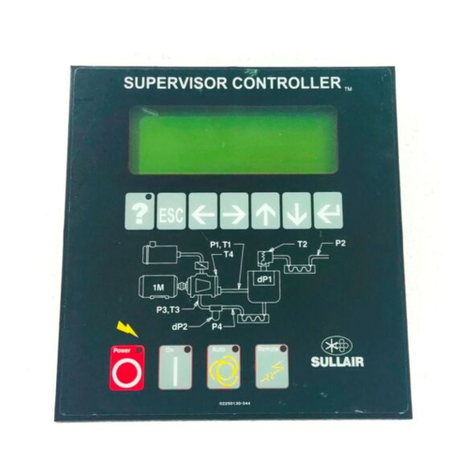
Sullair SUPERVISOR CONTROLLER User manual
Sullair
Sullair SUPERVISOR CONTROLLER Series User manual

Sullair
Sullair 900 User manual
Sullair
Sullair SUPERVISOR I User manual
