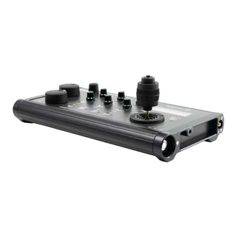
Slide Kamera FOOT CONTROLLERS HAD-10 User manual

HAD-10 | EXPANSION FOR KAIROS CONTROLLER
KAIROS rmware version 2.0.8 / 1.1.5 or higher
User Manual
FOOT CONTROLLERS™
available for download: www.manual.slidekamera.com
v03/2022

2
Table of contents
1. FOOT CONTROLLERS ................................................................... 3
1.1. Technical specication .............................................................. 3
2. Content of the set ............................................................................ 3
3. KAIROS CONTROLLER ................................................................. 4
3.1. Firmware update ....................................................................... 4
3.2. Connection ................................................................................ 4
4. Setup ............................................................................................... 5
4.1. Mapping the drives ................................................................... 5
4.2. Conguraiton ............................................................................ 5
4.3. Left / right irection ..................................................................... 6
5. Adjusting the spring tension ............................................................. 6
6. Disconnecting FOOT CONTROLLERS .......................................... 6
7. Maintenance and operation ............................................................. 7
8. Terms of warranty ............................................................................ 7
On the margins you will nd
information, which complement the
contents of the manual.
They are not essential for the
correct operation of the device, but
you might nd them useful.
TIP Before you start your work with the KAIROS controller we strongly
recommend to read the manual carefully.
Please note that using the controller in a manner inconsistent
with the instructions, any unauthorized repair attempts or any
kind of modication of the device can cause a damage the
manufacturer is not responsible for.
tel./fax (+48) 58 710 41 04
e-mail: of[email protected]
www.slidekamera.com
SLIDEKAMERA S.PAWELEC K.MIKULSKI S.K.A.
Kartuska 386
80-175 Gdansk
VAT No: PL5833444060

3
The set includes:
• FOOT CONTROLLERS (2 pcs)
• connection cables (2 pcs)
NOTE
The content of your kit may be
different if your controller is a
part of a set that was customised
for you.
Slidekamera FOOT CONTROLLERS are an expansion for the KAIROS
Controller to adjust the position of a chosen drive using feet.
Material: powder coated aluminium
Weight (1 pc): 1.6 kg
Dimensions (1 pc): 117mm x 100mm x 243mm
Compatible devices: KAIROS 2 - multiaxis controller
(rmware version 2.0.8 / 1.1.5 or up)
Number of devices controlled in
the same time: 1
1. FOOT CONTROLLERS
1.1. Technical specication
2. Content of the set

4
3. KAIROS CONTROLLER
3.1. Firmware update
3.2. Connection
The KAIROS Controller is the brain of the motion control system. It’s required
for the FOOT CONTROLLERS to work.
Before proceeding, make sure that the rmware of your KAIROS is updated.
FOOT CONTROLLERS are supported from version 2.0.8 (ethernet-based
systems with Slidelink 3.0) or 1.1.5. (systems equipped with Slidelink Pro)
and above.
To update the KAIROS controller, use the Slidekamera Firmware Updater
tool, which you can download from www.slidekamera.com/software.
1. Turn off the KAIROS before connecting FOOT CONTROLLERS.
2. Plug the D-SUB/Lemo cable to
the AUX port of the KAIROS
and the FOOT CONTROLLER
equipped with two Lemo sockets
(it’s irrelevant which socket you
use).
3. Connect FOOT CONTROLLERS
using a Lemo cable.
Always connect both FOOT CONTROLLERS!
4. Power-up the KAIROS Controller.
Detection of auxiliary manipulators
is performed at startup. Therefore,
connecting them to a powered-up
device won’t work.
NOTE
23

5
4.1. Mapping the drives
4.2. Conguraiton
By default, KAIROS controller uses its joystick and knobs to steer motion axes.
To use auxiliary inputs, you have to asign them to a chosen axis. It’s usually a
slider’s drive, but you can choose whatever axis you want - you can use FOOT
CONTROLLERS to move your head in the panorama axis or rack focus of
your lenses.
After powering up the controller and calibrating the drives enter the Device
Settings menu of a chosen drive.
Use the SET button for axes 1-3. For
all other drives, press the SETTINGS
button, navigate to Devices
Settings and choose your axis.
Choose Map to > from the
Axis menu
Additional inputs are added at the
end of the list.
Scroll down to controller no. 7 and
press the ENTER button on the
joystick to accept.
Exit the Menu using BACK button.
In the Live Mode, the new number is
displayed at the chosen drive. That
indicates the mapped controller.
To change the axis parameters, enter the Axis menu (press the SETTINGS
button, navigate to Devices settings and choose your axis).
Navigate to RAMP and SPEED
and alter the values using joystick.
To exit the menu choose BACK or
press the BACK button on the panel.
4. Setup
LIVE MY_GROUP ~
7S 124 50% 0.8s |
2P 49.6 99% 1.0s |
3T 39.0 99% 1.0s }
TIP
You can assign the unused input to
another axis and map the controller
to match your preferences (e.g.
you can use the speed-controlled
slider’s knob to steer the zoom
motor of your lenses).
<DEVICES SETT. ~
›1S SLIDER > |
2P PANORAMA > |
3T TILT > }
<SLIDER ~
Calibrate > {
›Map to > |
Info > }
<MAP TO ~
›1S SLIDER * {
2P PANORAMA |
3T TILT }
<SLIDER ~
Rebound <OFF>{
›RAMP 0.8s |
SPEED 50% }
<MAP TO ~
›7- {
BACK |
|

6
4.3. Left / right irection
The FOOT CONTROLLERS have no predetermined left / right assignment.
You can simply swap the controllers if you need to change the drive direction.
You can also use the INVERT feature in the Device Settings menu.
Slidekamera FOOT CONTROLLERS are
equipped with a spring tensioner. You can
adjust the resistance of the controllers to your
needs.
Use the 4mm hex key and rotate
the SPRING ADJUSTMENT screw.
Rotate clockwise to reduce the tension and
counterclockwise to increase it.
You can reduce the tension completely.
The controller won’t spring back after
pressing - it will stay pressed when
you remove your foot. You can use that
feature to move the slider constantly
with desired speed without keeping your
foot on the pedal.
To use the original mapping of the
axes, remap them manually
or reset the assignment using
Reset mapping from the
Devices settings menu.
Power down the KAIROS before unplugging the FOOT CONTROLLERS.
5. Adjusting the spring tension
6. Disconnecting FOOT CONTROLLERS
The adjustment screw is very
precise and takes a large
number of turns to change the
tension signicantly.
NOTE
<DEVICES SETT. ~
›Reset mapping > {
Reset settings > |
BACK > |

7
IMPORTANT INFORMATION FOR CORRECT DISPOSAL OF THE
PRODUCT IN ACCORDANCE WITH EC DIRECTIVE 2002/96/EC
At the end of its working life, the product must not be disposed
of as urban waste. It must be taken to a special local authority
differentiated waste collection centre or to a dealer providing
this service. Disposing of electronic equipment separately
avoids possible negative consequences for the environment
and health deriving from inappropriate disposal and enables
the constituent materials to be recovered to obtain signicant
savings in energy and resources. As a reminder of the
obligation to dispose of electronic equipment separately, the product is marked
with a crossed-out wheeled dustbin.
FOOT CONTROLLERS do not need any additional service or lubrication of
the components.
Maintenance procedures are reduced to keeping the equipment clean.
All SLIDEKAMERA products are covered by the manufacturer’s warranty for
a period of 12 months from the date of sale. Warranty covers production faults
and material defects, which resulted in the product malfunctioning. Warranty
covers the repair, or, if the repair proves impossible, replacement of the product
with a new one. However, the cost of repair of the product cannot overrun the
catalogue value of the product. The warranty does not cover damage and /
or product defects resulting from the improper usage, as well as not following
product maintenance specications.
The warranty excludes:
• unauthorized attempts to repair or modify
• mechanical damage caused during transport and operation of such features
as scratches, dents, pits, dirt, etc.
• ooding, moisture
To obtain warranty service the purchaser should deliver the damaged product
together with a proof of purchase or proof of payment (invoice, cash register
receipt). The product will be accepted for warranty service on condition, that it
is delivered with correctly lled in complaint form and properly protected during
transport.
The complaint form is available for download at: www.slidekamera.com
After the warranty period is exceeded any spare parts can be purchased
directly from the manufacturer or in any selected points of sale.
PLEASE NOTE:
Any package sent at the expense of SLIDEKAMERA S.K.A., Kartuska 386,
80-175 Gdańsk, will not be received.
7. Maintenance and operation
8. Terms of warranty

Table of contents
Other Slide Kamera Controllers manuals
Popular Controllers manuals by other brands

Grundfos
Grundfos LC Series Installation and operating instructions

PIETRO FIORENTINI
PIETRO FIORENTINI APERFLUX 851 Installation, commissioning and maintenance instructions

GF
GF EA25 instruction manual

FTE Maximal
FTE Maximal PRO 300 user manual

LINK-MI
LINK-MI LM-TV04S operating manual

Ridder
Ridder HortiMaX-Go installation manual