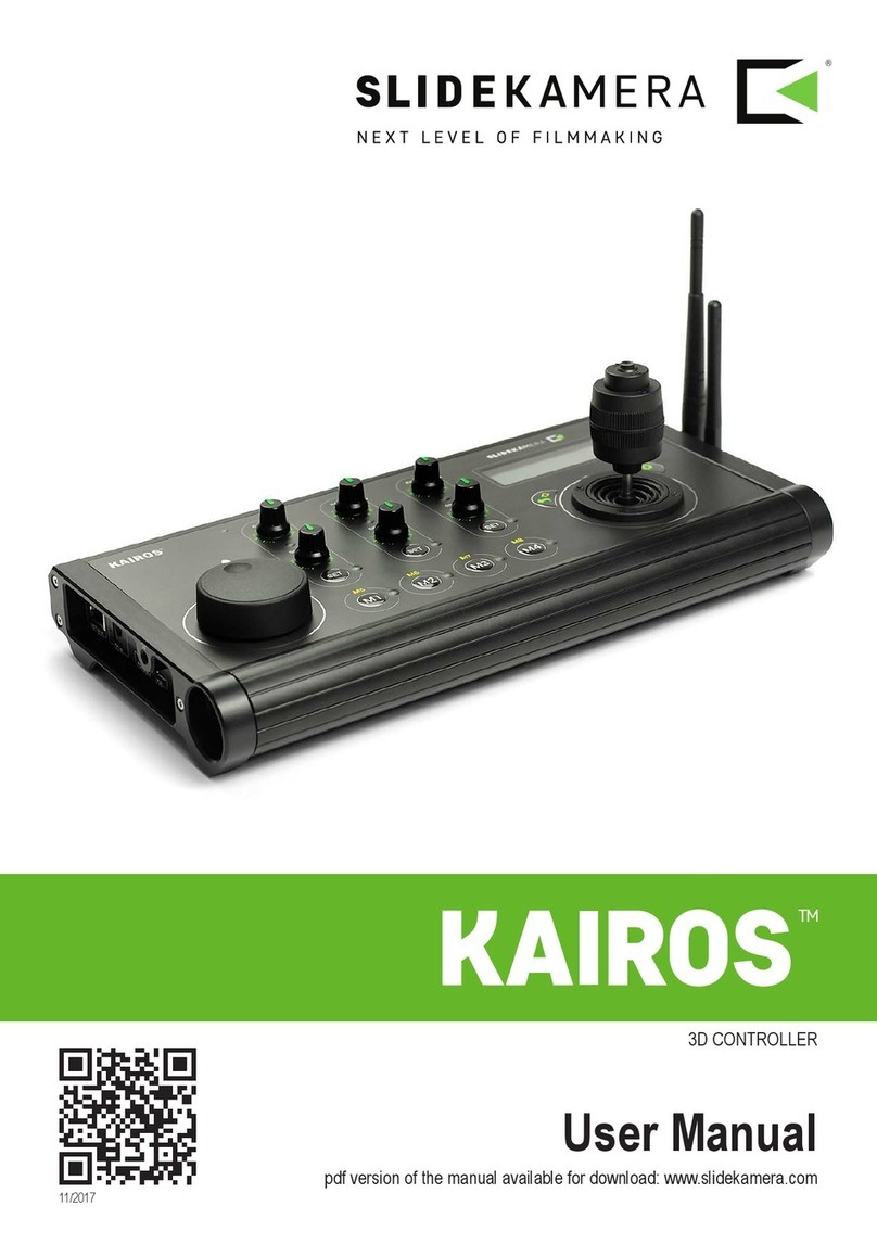
Slide Kamera KAIROS User manual

HPN-2 | 3D CONTROLLER
rmware version 1.0.9
User Manual
available for download: www.manual.slidekamera.com
v24/2020

2
Table of contents
1. KAIROS controller ........................................................................... 3
2. Technical specication ..................................................................... 3
3. Content of the set ............................................................................ 3
4. Construction .................................................................................... 4
4.1. Control panel ............................................................................ 4
4.2. Sockets and connectors ........................................................... 5
5. Connections ..................................................................................... 6
5.1. By wire ...................................................................................... 6
6. Power supply ................................................................................... 6
7. Preparing the controller ................................................................... 7
7.1. Turn on the controller ................................................................ 7
7.2. Detecting devices ..................................................................... 7
7.3. Alternative connections ............................................................. 8
7.4. Calibrating SLIDEKAMERA devices ......................................... 8
7.5. Calibrating PDMOVIE drives .................................................... 9
8. LIVE CONTROL mode .................................................................. 10
8.1. Axis custom menu ................................................................... 10
9. PARALLAX .................................................................................... 12
9.1. Conguring PARALLAX .......................................................... 12
9.2. Set ZERO ............................................................................... 13
9.3. Enable PARALLAX ................................................................. 13
10. Record and playback ................................................................... 14
10.1. Recording ............................................................................. 14
10.2. Playback ............................................................................... 15
10.3. Playback speed .................................................................... 15
10.4. Playback settings .................................................................. 16
11. KAIROS controller settings .......................................................... 16
12. Maintenance and operation ......................................................... 17
13. Terms of warranty ........................................................................ 17
On the margins you will nd
information, which complement the
contents of the manual.
They are not essential for the
correct operation of the device, but
you might nd them useful.
TIP Before you start your work with the KAIROS controller we strongly
recommend to read the manual carefully.
Please note that using the controller in a manner inconsistent
with the instructions, any unauthorized repair attempts or any
kind of modication of the device can cause a damage the
manufacturer is not responsible for.
Slidekamera Ofce
ul. Kartuska 386
80-175 Gdańsk, Poland
tel./fax (+48) 58 710 41 04
e-mail: of[email protected]
www.slidekamera.com
Slidekamera ®
High Engineering Technology CNC s.c.
Sebastian Pawelec Karol Mikulski
Glina 45
82-522 Sadlinki
VAT Identication Number:
581-188-33-32

3
HARDWARE VERISON
This manual is dedicated to KAIROS 2 (HPN-2) - the new revision
of the controller. Despite it’s phisical resemblance to previous device
- KAIROS 1 (HPN-1), many features and device’s rmware are
incompatible.
You can verify, your product’s version by the serial number.
The KAIROS 2 has the serial number above “2000 0000” (all models
purchased after 2020-01-01).
The set includes:
• KAIROS controller
• Wi-Fi antenna
• RF antenna
• HET-BUS steering cable (LEMO - RJ45)
• transport case
NOTE
The content of your kit may be
different if your controller is a
part of a set that was customised
for you.
KAIROS is a controller designed to work with SLIDEKAMERA motion control
devices. By default the controller can support up to 6 drives in any devices.
To control devices made of multiple motors, that enable motion in multiple
dimensions, KAIROS controller treats them as separate, independent drives.
For example, 2D heads (such as BULL HEAD or X HEAD) are recognized by
the controller as two separate drives: one for horizontal rotation of the camera
(PAN) and second - for its TILT.
Each of these drives is assigned to one axis. Parameters of every axis can be
adjusted separately by the KAIROS controller.
The rmware of the KAIROS controller is frequently upgraded and can be
easily updated by the user.
You can download the newest rmware at www.slidekamera.com/rmware
and a corresponding, newest manual at www.manual.slidekamera.com
Weight: 1.45kg
Dimensions: 339mm x 169mm x 114mm
Compatible devices: motion control devices equipped
with the HET-BUS socket
Number of devices controlled in the
same time: up to 6 independent axes
Supply voltage: 10..17V DC min 12W
Operating temperature range: 0 to +40ºC
Recommended relative humidity: < 90%
1. KAIROS controller
2. Technical specication
3. Content of the set

4
4. Construction
4.1. Control panel
[1] SLIDER (1st axis): use the knob to set the cart’s direction and speed.
[2] JOYSTICK - THE HEAD (2nd and 3rd axis): tilt the joystick left-right and
up-down to rotate the camera horizontally and vertically; ZOOM (5th axis):
rotate the joystick to change the zoom of the lens;
[3] ENTER button: there’s a button on the top of the joystick, it’s used to change
settings of the controller or navigate in the options menu;
[4] FOCUS (4th axis): use the knob to control the focus lens motor;
[5] IRIS (6th axis): use the knob to control the iris lens motor;
The position of the [4] FOCUS and [5] IRIS knobs corresponds directly to the
position of a focus and iris rings on your lens:
[6] SETTINGS button: enter the settings menu; depending on the current
dialog displayed on the screen, the button enters appropriate settings;
[7] BACK/SHIFT button - dual-function button: use this button to access
additional memory banks [9] and settings for axes 4-6 (hold it to access
funkctions marked yellow); in menus and options dialogs use this button to go
one step back;
STOP
(center-click)
50% LEFT 50% RIGHT 100% RIGHT100% LEFT
[12] axis settings [11] SCREEN
[8] MEMORY buttons
[1] SLIDER
(1st axis)
[2] JOYSTICK
(2nd, 3rd and 5th axis)
[7] BACK / SHIFT button
[6] SETTINGS button [3] ENTER button
[9] PLAYBACK SPEED
[4] FOCUS
(4th axis)
[5] IRIS
(6th axis)
[10] LED - charge indicator
In some circumstances (overhang
system, operating from the other
side, etc) you will nd, that the drive
moves in the opposite direction.
You can reverse the direction of the
drives in the AXIS SETTINGS menu
and operate as usual.
For details reffer to “8.1. Axis
custom menu” (p. 10).
TIP

5
[8] MEMORY buttons - use them to access memory banks; press M1-M4 to
access banks 1-4, press SHIFT + M1-M4 to access banks 5-8. Long press to
enter the memory settings, short press for execute recorded data. You can nd
more about memory banks in “10. Record and playback” (p. 14).
[10] LED - charge indicator - indicates the state of the device’s power supply.
OFF - there’s no power supply connected to the device;
RED - external power connected, the internal battery is being charged;
GREEN - external power connected, the internal battery is fully charged;
FLASHING RED/GREEN - error of the power supply.
[11] SCREEN - shows current device’s state, settings menus, infos and many
more.
[12] AXIS SETTINGS - axes 1-3 individual hardware controllers to set working
parameters; for details reffer to “8. LIVE CONTROL mode” (p. 10).
[9] PLAYBACK SPEED - with this knob you can change the speed of the
drives during playback of the motion stored in memory banks.
axis number
SPEED - speed adjustment (limits top speed of the drive)
axis settings LED (GREEN when editing axis settings)
RAMP - smooth start and stop adjustment („ramping”)
axis settings button („SET”) - press to enter axis settings
axis activity indicator - GREEN when the axis is enabled
TIP
To access settings for axes 4-6,
press SHIFT + SET (1 for 4th axis,
etc). You can change the working
parameters of those axes in the
settings menu - “8.1. Axis custom
menu” (p. 10).
4.2. Sockets and connectors
HET-BUS socket PLAYBACK SPEED
ETHERNET socket USB-C (charging and maintenance)
AUXILIARY connector (COM port)
RF antenna connector
POWER button Wi-Fi antenna connector

6
5. Connections
5.1. By wire
KAIROS controller can be connected to any device equipped with HET-BUS
socket (RJ-45 or LEMO), such as slider drives and remote heads.
Most devices have two HET-BUS ports and multiple devices can be daisy
chained to one controller (order of the devices is not important).
Connecting cables:
• connect KAIROS controller to the rst device of your choice, to it’s HET-
BUS IN socket using steering cable;
• further device (if there is any) connect by connecting it’s HET-BUS IN
socket with HET-BUS OUT socket of the previous device;
• connect power supply to devices, that require external power source for
their motors (heads, sliders, etc.), if you’re using RJ-45 connector, plug
the power adapter to all devices; if you’re using HET-BUS with LEMO
connectors, plug the power to the rst device;
• KAIROS controller is powered by the HET-BUS connector and requires no
additional power supply, when connected to compatible drive.
Examples of connecting KAIROS controller with other devices:
IN
OUT
X MOTOR
IN
OUT
12V
KAIROS
BULL HEAD
POWER SUPPLY
IN
OUT
X MOTOR
IN
OUT
12V
KAIROS
BULL HEAD
POWER SUPPLY
6. Power supply
KAIROS controller has a built in battery, that enables the controller to work
wireless without any power adaptors.
KAIROS battery is charged by:
• HET-BUS socket - during operation with compatible devices connected to
the socket (please note, that not all devices are able to charge the KAIROS
controller via HET-BUS);
• USB-C socket - you can use any standard phone charger;

7
To turn the controller on, push the
POWER button on the right hand
side. The splash screen with the
rmware version number will appear.
After connecting and powering the
devices, KAIROS controller detects
available drives.
name of the drive
calibration status
battery charge
scrollbar
calibration mode
cursor
axis number
The LCD screen displays the list of
drives and assigned axes.
Use the joystick to navigate through
menu pages. To change a value
indicated by the cursor and <>
brackets, move the joystick left/right.
If a connected device is not visible on
the list, check the cable connections
and select “Repeat detection”.
Next to the axes names there’s calibration status indicator:
- - the axis is not calibrated, you have to calibrate in order to use it;
^ - the axis has been calibrated and you can use the old data;
™ - safety limits are removed, the axis drive can work innitely;
Make sure that the SLIDER knob is in the center position (speed set to 0%)
and select “Continue” to calibrate selected axes.
You can set the calibration method (use joystick to move the cursor to the
corresponding axis and change the parameter by moving the joystick left-right):
- - the calibration will not be performed, default for previously calibrated drives;
A - automatic calibration (available only for the slider and PDMOVIE motors -
the drive will gently bounce off the edges to nd the working range);
M - manual - working range dened by user.
7. Preparing the controller
7.1. Turn on the controller
7.2. Detecting devices
KAIROS 2
Version: 1.0.9 -
DETECTING
DEVICES...
DEVICES LIST ~
Continue > |
›1S SLIDER -<M>|
2P PANORAMA ^ - }
DEVICES LIST ~
›3T TILT ^<->{
4F PDM red - M |
5Z PDM green - M }
DEVICES LIST ~
›6I PDM blue -<M>{
Repeat detection |
|
TIP
The scrollbar arrows indicate if
there are any positions in the menu
above or below the current screen.
The > bracket indicates that the
position on the list contains another
dialog (e.g. sub-menu).
NOTE
The KAIROS will always list three
PDMOVIE (PDM) drives if a head
with compatible LCS port is con-
nected, even if the drives are not
present.
NOTE
Working with safety limits removed
can cause damage and/or injuries.
For safety reasons the KAIROS
controller cannot set the axes to in-
nite mode, but it may be applied by
another device, e.g. for diagnostics.
NOTE
Always recalibrate the drives, if the
hardware setup was modied, the
drive was moved manually or the
power was lost during operation.

8
Using the joystick and slider’s knob
move the camera in all axes to one
of the extreme positions (it doesn’t
matter left or right). Be careful not to
touch the slider’s end brackets with
the cart, or not to touch the head with the camera lens or the battery, as you’re
operating now without any safety limits.
You can reduce the drive’s speed with the corresponding knobs on the AXIS
SETTINGS panel to gain the precision of the movement.
Press ENTER to continue.
Calibration is a process of setting safety limits - extreme positions, that will
never be exceeded. This prevents breaking off cables or damaging the camera.
7.3. Alternative connections
The KAIROS controller has multiple options to connect devices; to change
the connection type, that the controller use, press SETTINGS button on the
DEVICES LIST screen or during DETECTING DEVICES. Additional menu will
appear.
Select the connection type and wait for the changes to be applied.
Some additional conguration may be required.
You can change the Connection setting:
HETBUS - standard communication port for SLIDEKAMERA drives; it’s wired
connection that’s using lemo or RJ-45 plugs (for the KAIROS controller it’s mini-
lemo plug on the left hand side of the controller);
ETHERNET - you can connect the KAIROS controller to the local network and
control the drives, that are attatched to it; use the RJ-45 socket to plug the
ETHERNET cable;
WIFI - the controller can be connected by Wi-Fi to the local network or to
compatible drives, that act as Access Point; note that for properly congured
Access Points you have to provide the password in order to connect to the
network;
RF - direct radio connection for compatible SLIDEKAMERA devices, more
reliable and with less delay than standard Wi-Fi connection;
Do not connect network devices
to the ports of the SLIDEKAMERA
drives described as HET-BUS, as
they’re not compatible with the
ethernet signal, despite similar
connector.
NOTE
7.4. Calibrating SLIDEKAMERA devices
CALIBRATION ~
Click ENTER to set
START bound
<DETECT SETTINGS ~
›Connect. <HETBUS>
CANCEL

9
AUTO
If you’re using lenses with hard-stops, you can calibrate the drive automatically,
by using the AUTO (A) method in the devices list menu. The drives will run to
the extreme positions to check it’s working range during calibration process.
You can recalibrate the PDMOVIE drive automatically by holding the button
on the drive.
MANUAL
You can also use the MANUAL method. In this mode you will have to skip the
setting of START and END points on the PDMOVIE drives during calibration
(set those positions for SLIDEKAMERA drives only, or - if calibrating PDMOVIE
drives only - press ENTER on the CALIBRATION screen without setting any
postitions).
Perform the actual calibration on the drive by holding the button on the drive, or
use the by-hand approach described for focus-by-wire lens.
If you’re using lens with focus-by-wire ring, run the manual calibration
procedure on the KAIROS controller, as with hard-stops lens. Perform the
acutal calibration on the drive by rotating the focus ring by hand to one extreme
position, then to the second extreme position, and move the ring a little back to
the direction of the rst position.
The drive is calibrated and should rotate slowly to the position indicated by
the controller. The motor is engaged and you won’t be able to freely rotate the
lens ring.
Lenses with hard-stops
Focus-by-wire
Set an opposite extreme position of
the camera for all axes.
The calibration process is nished.
Press ENTER to conrm, or BACK
to repeat the process if you want to
calibrate the drives again.
Press ENTER to continue.
7.5. Calibrating PDMOVIE drives
TIP
If you don’t know, what type of
lens do you have, rotate the ring
on the lens barrel. If it stops at the
extreme positions and you cannot
rotate the ring any further, it’s the
manual lens with hard stops. If
you can rotate the ring on and
on, it’s the electronic lens with
by-wire engine. Note, that there are
lenses with both type of rings, e.g.
electronic by-wire for focus ring and
mechanical ring with hard-stops
for zoom.
NOTE
During manual calibration of the
PDMOVIE drives always observe
the scale on the lens and do not
exceed the extreme markings. It’s
crucial to keep the precision and
repeatability of the lens control
system.
NOTE
For safety reasons the KAIROS
controller will not work with the
drives, that are not calibrated.
CALIBRATION ~
Click ENTER to set
END bound
CALIBRATION ~
Calib. completed
ENTER: Finish
BACK: Repeat calib.

10
To access settings for axes 4-6,
press SHIFT + SET (1 for 4th axis,
etc). You can change the working
parameters (RAMP, SPEED) of
those axes in the settings menu.
TIP
You can also access all axes
menus from the main settings menu
- for details reffer to “11. KAIROS
controller settings” (p. 16).
TIP
8. LIVE CONTROL mode
8.1. Axis custom menu
After successful calibration the safety limits are applied and the KAIROS
controller automatically runs LIVE CONTROL mode. It’s basic mode, used to
operate connected drives in real time.
The device is immediately ready to work. You can control your drives with the
joystick and/or the knobs on the control panel of the KAIROS controller.
The LCD screen displays all
parameters of the devices. These
values can be altered by using
the control panel of the KAIROS
controller.
To scroll down the device’s list press
ENTER (as you cannot use joystick
for scrolling and navigating right now
- it’s used to control your head or
other devices).
To enter the axis custom menu, press SET button on the axis settings section
of the control panel. Axis settings LED will light up.
Live - behaviour of the axis in live mode:
ON - the axis is active in live mode;
PRLX - available for panorama axis only: the head works in parallax mode
- advanced solution for tracking shots; position of the head is linked
to the position of a slider (the camera rotates as the slider moves),
movement of the joystick doesn’t affect the rotation of the head; for
setting the Parallax mode refer to “9. PARALLAX” (p. 12).
OFF - the axis is inactive.
position - actual position of the drive, measured from one calibration point;
for linear drives (e.g. sliders) the value corresponds to position in millimeters,
for angular drives (e.g. remote heads) - position in degrees; for the PDMOVIE
drives the position values are steps in 0-7200 range;
RAMP - smooth start and stop adjustment („ramping”), specied in seconds;
the value is adjusted independently for each axis by a knob on the control panel
of the KAIROS controller;
SPEED - drive’s speed limit, specied as percentage of its maximum speed;
the value is adjusted independently for each axis by a knob on the control panel
of the KAIROS controller;
LIVE CONTROL ~
1S 124 32% 0.9s |
2P 49.6 44% 1.0s |
3T 39.0 99% 2.1s }
LIVE CONTROL ~
4F 2356 99% 0.1s {
5Z 346 99% 0.1s |
6I 1289 99% 0.1s |
axis number
drive indicator
position speed ramp
scrollbar

11
To remap drive’s assignment, enter
the Map to in Settings menu for an
axis currently assigned to the drive
you want to change. The selected
drive is marked with a * symbol.
Navigate the cursor to the axis you
want the drive do be assigned to
and press ENTER. The drive’s name
will appear next to the chosen axis
number (if there is any drive assigned
to that axis, the drives will change places).
Playback - behaviour of the axis during playing the content of memory
banks:
ON - the axis plays back recorded data;
MAN - manual mode; recorded data for this axis will be discarded, Live
mode will be used instead (you can operate this axis by hand during
playback);
PRLX - available for panorama axis only: the head works in parallax mode
- advanced solution for tracking shots; position of the head is linked to
the recorded slider’s position (the camera rotates as the slider moves),
movement of the joystick doesn’t affect the rotation of the head;
OFF - the axis is inactive.
Invert - reverse the direction of the motion; relevant in some hardware
congurations (e.g. when operator of the controller stands on the other side of
the slider, or the remote head operates upside down):
ON - the motion is reversed;
OFF - the axis operates as usual.
Rebound - the direction of the motion will be reversed when the drive (e.g.
the slider’s cart) reaches one of the extreme positions; this feature is useful for
a simple loop of a slider’s cart - when Rebound is enabled, you can simply set
a slider’s speed with a Slider knob and the cart will run back and forth until you
set the Slider knob to 0.
ON - the Rebound is enabled;
OFF - the Rebound is disabled, the drive stops at the end of a working
range dened in calibration process.
Parallax - advanced tracking mode, used to keep the object in frame
regardless the position on the slider; for setting and operating the Parallax
mode refer to “9. PARALLAX” (p. 12).
Calibrate - recalibrate the axis; use this option to perform calibration for
selected axis only;
Map to - set a different drive to use particular controller (e.g. you can set the
joystick to control the motion of a slider, etc.).
Info - additional informations about the axis and assigned drive.
CANCEL - discard changes and exit the menu;
BACK - save changes and exit.
TIP
Recorded keyframes and moves
are assigned to the drive, not the
axis number - so when you swap
the drive’s axes the motion will be
played back correctly.
<MAP TO ~
›1S SLIDER * |
2P PANORAMA |
3T TILT }
<MAP TO ~
1P PANORAMA |
›2S SLIDER * |
3T TILT }

12
9. PARALLAX
The KAIROS controller is equipped in
auto tracking feature - PARALLAX.
It is designed to keep correct angle of
the camera during motion of the slider
and to eliminate the parallax effect.
That enables the camera to hold
the subject in the frame and to keep
correct composition of the image.
PARALLAX feature has to be
congured and calibrated to work
properly.
To congure PARALLAX go to SETTINGS for the Panorama axis by pressing
SET button on the Axis settings panel and choose Parallax > .
Choose the drive you want the head
to be linked to. Usually it’s the slider’s
drive. In most cases there’s no other
choice, but you may have other
sliders in your system to choose from.
You can change the assignment later
using the Set link > option.
The PARALLAX is enabled, you have
to congure the settings to make it
work properly.
You have to set two parameters:
“target” and “zero”.
You can discard all your settings by
selecting Reset option.
Set TARGET
set START point
set END point
• choose Set target >
from the Parallax settings menu;
• set START point - set the slider’s
cart at the beginning of your
working range and aim the camera
at the lmed object to set correct
composition of the frame;
• conrm by pressing ENTER;
• set END point - set the slider and
the head in the opposite position,
aim the camera to set your object
in frame;
• conrm by pressing ENTER;
• the controller will return to Parallax
settings menu.
9.1. Conguring PARALLAX
<PARALLAX LINK ~
›SLIDER
<PARALLAX SETT. ~
›Set target > |
Set zero > |
Set link > }
<PARALLAX SETT. ~
›Reset {
Back |
|

13
Setting “zero” is optional, but highly recommended. By setting additional point
of reference for the PARALLAX system, you enable advanced mode, that
calculates exact position of the lmed object and allows you to work precisely,
on long focal length, at short distance to the object or at high angle.
To enable PARALLAX feature, go to
the PANORAMA axis settings and set
Live and/or Playback mode
to PRLX.
After enabling PARALLAX in Playback
mode, you will notice that SPEED and
RAMP settings on the screen are not
available for Panorama axis, as the
values are overridden by the tracking
system.
Enabling the PARALLAX in Live mode will control the Panorama axis during
manual operation, but recorded moves will be played back as are stored in the
memory banks.
Enabling PARALLAX in Playback mode will force the Panorama axis to discard
the recorded data and will link it to the motion of a slider, using current TARGET
and ZERO settings. The recorded data will not be removed and will be used to
playback when you set back the Playback mode to ON.
The PARALLAX feature is fully congured.
• choose Set zero >
from the Parallax settings
menu;
• set ZERO - set the slider’s cart on a side and rotate the head to align the
lens axis parallel to the slider; you can use the viewfinder of the camera
to set a point on the axis of the slider (e.g. 1/4” mounting thread) in the
middle of a frame;
• conrm by pressing ENTER;
• the controller will return to Parallax settings menu.
set ZERO
9.2. Set ZERO
9.3. Enable PARALLAX
<PANORAMA ~
Live PRLX |
›Playback <PRLX>|
Invert OFF }
LIVE CONTROL ~
1S 124 32% 0.9s |
2P 49.6 --Prlx-- |
3T 39.0 99% 2.1s }

14
10. Record and playback
KAIROS controller is equipped with 8 memory banks. Each one can store
store a single camera position, A-B move or recorded free move.
Memory banks 1-4 are available directly with the M1-M4 buttons. To use
memory banks 5-8, hold BACK / SHIFT button and press a M1-M4 button.
To record a position or move in the
memory of the KAIROS controller,
hold one of the memory buttons. A
menu will appear, that corresponds to
the chosen memory slot.
New keyframe > - record a single position of a camera; you can use
this option to store different positions in memory banks and restore them, e.g.
during live show to switch the camera between saved views.
New trajectory > - record a simple A-B move (motion between
two specied positions).
New track record > - record a free move
• select New keyframe >
and press ENTER;
• set the position of the camera
with the joystick and knobs;
• conrm by pressing ENTER.
The keyframe is recorded in the memory bank.
• select New trajectory
> and press ENTER;
• move the camera to the rst
(START) position
• conrm by pressing ENTER;
• move the camera to the second
(END) position
• conrm by pressing ENTER;
The trajectory is recorded in the
memory bank.
• select
New track record >
and press ENTER;
• move the camera to the point,
where you want to begin your
recording;
• press ENTER to start recording;
• perform the move using joystick
and knobs;
• press ENTER to stop recording;
The track (free move) is recorded in the memory bank.
10.1. Recording
<SLOT M1 ~
›New keyframe >
New trajectory >
New track record >
<SAVE KEYFRAME ~
Move to change pos.
ENTER: Set KEYFRAME
<SAVE TRAJECTORY ~
Move to change pos.
ENTER: Set START
<SAVE TRACK ~
Ready to record
track!
ENTER: Start RECORD
<SAVE TRACK ~
Move to change pos.
00:15.5
ENTER: Stop RECORD
<SAVE TRAJECTORY ~
Move to change pos.
ENTER: Set END

15
To play back stored data, press once the button corresponding to the chosen
memory bank.
KEYFRAME
TRAJECTORY or TRACK
If a KEYFRAME is stored in a memory
bank, the camera will immediately go
to the recorded position after pressing
the memory button.
To play a TRAJECTORY or TRACK:
• press the memory button;
• the camera will go to the START
point immediately and pause;
• press the ENTER button or the
memory button to trigger the move;
• the drives will play back recorded
move;
• the controller will revert to LIVE
CONTROL after nished playback.
You can control the motion of the camera during moving to KEYFRAME or
playing the TRAJECTORY (A-B move).
The axes will respect the SPEED and RAMP settings, that were set before
triggering the playback (changing the RAMP and SPEED knobs during the
played motion don’t affect played motion).
All axes, regardless the speed settings, will be played back in sync - all drives
will start and stop playback exactly at the same moment. The faster drives will
be slowed down to keep synchronisation with axes with slower settings.
Playing the recorded TRACK (free move) you cannot alter the SPEED and
RAMP settings of the axes, as they are “baked in” in the recording.
PLAYBACK SPEED knob
To change the time of the recording
(for moving to KEYFRAME, playing
the TRAJECORY or the TRACK)
you can use the PLAYBACK SPEED
knob. It sets the global speed for
all axes during playback. You can
stretch the time of the motion, but the
motion’s path remain intact.
You can rotate the knob anytime, before playback, during setting start position,
waiting for trigger command or during playback.
If you change the PLAYBACK SPEED, the value in % will be visible on the
screen and total time of the recording will be changed accordingly. This way
you can set a playback time precisely.
10.2. Playback
10.3. Playback speed
TIP
If you press the ENTER button
before the camera reaches the
START point, you will turn on the
“Instant run” mode, that will trigger
the playback as soon as the camera
reaches the START point.
TIP
The RAMP settings are
independent - you can change
accelerations of each axis
separately using different RAMP
settings, therefore you can alter
the synchronization in between
the START and STOP points (the
START and STOP are always in
sync for all axes).
TRACK M4 ~
Play Speed: 100%
A:00:03.5 T:00:11.4
______
TRACK M4 ~
Moving to start...
ENTER: Instant run
TRACK M4 ~
Play Speed: 100%
A:00:00:0 T:00:11.5
ENTER: Run �
TRACK M4 ~
Play Speed: 100%
A:00:00:0 T:00:11.5
ENTER: Run �
TRACK M4 ~
Play Speed: 50%
A:00:00:0 T:00:23.0
ENTER: Run �
KEYFRAME M1 ~
Play Speed: 100%
A:01:12.1 T:13:32.4
______
time elapsed
total move timeprogress bar

16
10.4. Playback settings
When a TRAJECTORY or TRACK is
stored in the memory bank, additional
Settings option in the memory
menu appears.
In LIVE CONTROL mode press SETTINGS button to enter the device’s settings
menu:
Repeat - number of repetitions of
recorded move; for innite loop set
value below zero, ∞ mark will appear.
Detect devices > - search for new drives connected to the controller;
Devices settings > - access to axes menus, also available by
pressing SET buttons on axis settings panel;
Devices alerts > - list of alarms (if there were any) for diagnostics
and troubleshooting;
Memory slots > - management for the memory banks:
Save preset > - save recordings in the memory bank as a preset
for further use;
Load preset > - load previously saved preset (note, that this will
overwrite current memory banks);
Reset slots > - purges memory banks;
Backlight > - set the light level for the screen and status LEDs on
the device; decreasing light levels may extend device’s battery life; increase
brightness gains visibility in bright conditions (direct sunlight, heavy studio
lighting, etc).
Time & date > - set current timezone, time and date;
About > - technical informations about the device (name, rmware, serial
number, etc.)
Return - the way the drives return
to START after nished playback:
OFF - for one repetition the drives will not return to the START position; for
multiple repetitions OFF works as FAST RET.;
FAST RET. - the drives will return to START as fast as possible after
nished playback;
MIRROR - after nished playback the recorded move will be played back
again in reverse;
Invert - plays the recorded move in reverse;
11. KAIROS controller settings
The controller will update the
time and date automatically, if is
connected to the ethernet with
internet access.
TIP
<SLOT M1 ~
›Settings >
New keyframe >
New trajectory >
<TRAJ.SETTINGS ~
›Repeat <0>|
Return OFF|
Invert OFF}

17
IMPORTANT INFORMATION FOR CORRECT DISPOSAL OF THE
PRODUCT IN ACCORDANCE WITH EC DIRECTIVE 2002/96/EC
At the end of its working life, the product must not be disposed
of as urban waste. It must be taken to a special local authority
differentiated waste collection centre or to a dealer providing
this service. Disposing of electronic equipment separately
avoids possible negative consequences for the environment
and health deriving from inappropriate disposal and enables
the constituent materials to be recovered to obtain signicant
savings in energy and resources. As a reminder of the
obligation to dispose of electronic equipment separately, the product is marked
with a crossed-out wheeled dustbin.
KAIROS controller does not need any additional service or lubrication of the
components.
Maintenance procedures are reduced to keeping the equipment clean.
All SLIDEKAMERA products are covered by the manufacturer’s warranty for
a period of 12 months from the date of sale. Warranty covers production faults
and material defects, which resulted in the product malfunctioning. Warranty
covers the repair, or, if the repair proves impossible, replacement of the product
with a new one. However, the cost of repair of the product cannot overrun the
catalogue value of the product. The warranty does not cover damage and /
or product defects resulting from the improper usage, as well as not following
product maintenance specications.
The warranty excludes:
• unauthorized attempts to repair or modify
• mechanical damage caused during transport and operation of such features
as scratches, dents, pits, dirt, etc.
• ooding, moisture
To obtain warranty service the purchaser should deliver the damaged product
together with a proof of purchase or proof of payment (invoice, cash register
receipt). The product will be accepted for warranty service on condition, that it
is delivered with correctly lled in complaint form and properly protected during
transport.
The complaint form is available for download at: www.slidekamera.com
After the warranty period is exceeded any spare parts can be purchased
directly from the manufacturer or in any selected points of sale.
PLEASE NOTE:
Any package sent at the expense of HET-CNC s.c., 80-175 Gdańsk, ul.
Kartuska 386 will not be received.
12. Maintenance and operation
13. Terms of warranty

Other manuals for KAIROS
1
This manual suits for next models
1
Table of contents
Other Slide Kamera Controllers manuals