Slider Metro E3 User manual

User Manual
Metro E3

User Manual
Metro E3
Welcome to the SLIDER!
Thank you for purchasing the METRO E3 from
SLIDER!
We take pride in bringing you a quality
product that will offer years of enjoyment.
Please read and under- stand this manual
fully before assembling and riding your bike;
the latest version of your manual is available
at www.slider.eu. And be sure to watch the
official SLIDER assembly video available at
www.slider.eu or at the QR code shown here.
Additional information about your SLIDER can be found in our Help
Centre at www.slider.eu.
Be sure to check all hardware for correct (see “Unboxing” ) during
assembly. Before each ride, follow the recommendations in the Safety
check in manual. Finally, take care of your new SLIDER by following
the guidelines in “Maintenance” . If you’re not sure you have the skills,
experience, and special tools required for assembly and maintenance,
get help from a local, certified, and reputable bike mechanic.
WE ARE HERE TO HELP!
If you have questions after reading this manual and watching the
assembly video, please consult the SLIDER Help Centre, contact us by
email, and/or give us a call on the phone. Thanks for riding SLIDER!
SLIDER Help Centre : www.slider.eu
E-mail : contact@slider.eu
Phone : +35-9897494937
0101

1.Precautions..............................................................................03
2. Assembly Instructions.............................................................04
3. Assembly Step Instructions and Precautions.......................05-17
4. Battery Precautions................................................................18-27
5. function test............................................................................28-30
5. Precautions for use.................................................................31-38
6. maintainance..........................................................................39
7. safety checklists......................................................................40-62
8. warranty...................................................................................63-65
Table of content
SLIDER METRO E3 Folding Electric Bike
User Manual
02

Using this manual
This manual contains critical details about how to safely operate and
maintain your SLIDER. Read it carefully and familiarize yourself with
your ebike before riding it. Pay special attention to the safety messag-
es shown here.
NOTICE: A “notice” is important information that can help
you avoid bike/property damage or extend the life of parts
and the bike.
CAUTION: A “caution” statement indicates a haz- ardous
situation that, if not avoided, could result in minor or
moderate injury or property damage.
A “warning” statement indicates a hazardous situation
that, if not avoided, could result in death, serious injury, or
property damage.
A “danger” statement indicates a haz- ardous situation
that, if not avoided, has a very high risk of death, serious
injury, or property damage.
Riding any bike or other vehicle always involves some risk of serious injury or
death. Your safety depends on many factors including your bike knowledge,
your bike’s maintenance, foreseeable riding conditions, etc. There are also
factors we cannot control or anticipate in every situation or condition while
riding. This manual makes no representations about the safe use of bikes
under all conditions. If you have any questions you should contact SLIDER
immediately.
Assembly and first adjustment of your bike from SLIDER requires special tools
and skills. We recommend that you have this done by a certified, reputable
bike mechanic. Keep this manual and any other documents that came with
your BIKE. All content in this manual is subject to change or withdrawal
without notice. Visit www.slider.eu to view and download the latest version.
SLIDER bikes makes every effort to ensure the accuracy of its documentation
and assumes no responsibility or liability if any errors or inaccuracies appear
within.
03

Assembly instructions for the SLIDER
The following steps provide an overview of how to assemble your
METRO E3 from SLIDER. They are not a complete or comprehensive
manual of all aspects of assembly, maintenance, and repair, which
involve specialized tools and skills. We recommend you consult a
certified, reputable bike mechanic to assist in the assembly, repair,
and maintenance of your SLIDER.
Fully assembled SLIDER METRO E3 FOLDING E-BIKE
04

Please note that your SLIDER may include components that look
different from those in the illustrations above and elsewhere in this
manual. Such changes help ensure uninterrupted shipping. Our
engineers rigorously test each component to guar- antee quality and
compatibility.
WARNING: Incorrect assembly, maintenance, or use of your
ebike can cause component or performance failure, loss of
control, serious injury, or death. Even if you’re an experienced
bike rider, you must read and understand the entire manual and
any documentation provided for subcomponents or accessories
before riding. If you are not sure you have the experience, skills,
and tools to correctly perform all assembly steps in the manual
and the assembly video at www.slider.eu , consult a local,
certified, reputable bike mechanic.
Step 1 Unboxing
Check if the contents are complete
Main body Front wheel Seat Charger HEX key
M5
05

1. Unboxing the bike. Open the bike box with the help of another person
capable of safely lifting a heavy object, remove the ebike from the bike
box, placing it upright on the back wheel and front fork protector plate.
Carefully remove the packaging material protecting the bike frame and
components, and keep the packaging materials in case you want to ship
the bike. Otherwise, recycle these materials, especially cardboard and
foam, wherever possible. Remove the small box from the bottom of the
bike box and carefully set out the contents. Ensure all of the following
pieces are included with the ebike like picture.
If anything is missing, please contact SLIDER.
We also recommend the following (not included) for assembly and main-
tenance:
-A strong friend
-Flat-side cutters
-15 mm pedal wrench
-Bicycle grease
-Clean shop towel or paper towel for cleaning excess grease
-Bike pump with Schrader valve and pressure gauge
-Torque wrench (3 Nm-60 Nm) with Allen bits
Step 2 Fixed Folding Tube
06
Make sure the folding tube is locked
Caution: Must be lock tide before riding !
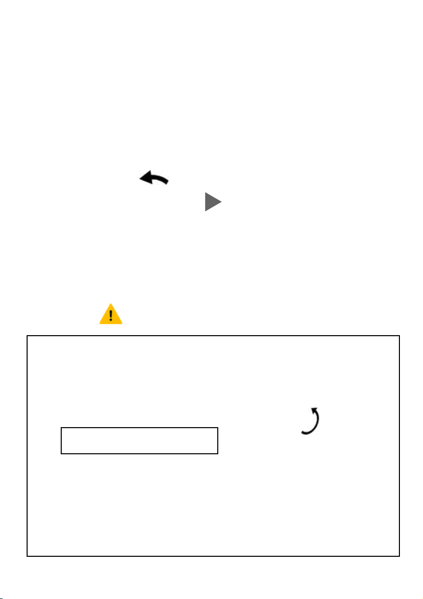
2. After taking out the bicycle and checking that there is no problem, first
rotate and fix the handlebar of the bike as shown in the picture. Please be
sure to lock the handlebar tightly. If you find that it cannot be fixed or the
tenon is damaged, please contact us and we will serve you. In addition,
please use the Allen wrench to confirm that all the screws on the handle-
bar have been tightened. If you find any untightened screws or other
problems, please contact our customer service to avoid accidents when
riding. cause danger.
Step 3 Frame Expand
07

(a)
(b)
3. Work with your strong friend to unfold the folded bicycle to the riding
state, and follow the above steps to lock it.
08

(a) After unfolding, align the shock absorber tenon on the rear fork with
the frame buckle and insert it, (b) and turn the screw on the quick release
kit to lock it to tightly be like (c).
(c)
Caution: Must be lock tide before riding !
09

Step 4 Install Front Wheel
4. Hold the quick-release lever in line with the axle and tighten the
thumbnut until the lever can stay parallel to the floor without being held.
Use the palm of your hand to close the lever fully, without touching the
brake rotor. The quick-release lever secures the front wheel to the bike, so
it’s important that the thumbnut is tight enough that the closed lever has
adequate clamping force to keep the axle and wheel firmly in place.
When you close the lever, there should be enough resistance that it leaves
an imprint in your hand.
10
Caution: Front wheel Must be lock tide before riding !
After confirming that the direction is consistent, first loosen the quick
release screw (but do not disassemble it), align the hole on the front fork
and install the wheel, and then tighten the quick release screw after
confirming that the direction of the wheel and the front fork is not
offset, and Tighten the quick release kit.
11

Check the security of the front wheel and quick-release lever. If it’s too
easy or too difficult to close, adjust the lever tension by turning the
thumbnut one turn, then close the lever. Check the front wheel security
on a regular basis: the front wheel should always be fully seated in the
dropouts of the front fork, and the quick-release lever should always be
properly secured.
Check the security of the rear wheel. The rear wheel security and hard-
ware torque should also be checked on a regular basis . Either wheel
can become loose or unsecured with normal use.
WARNING: An improperly secured
front or rear wheel can cause loss of
control, accidents, serious injury, or
death. Check that both wheels are
properly secured during assembly and
before each ride.
12

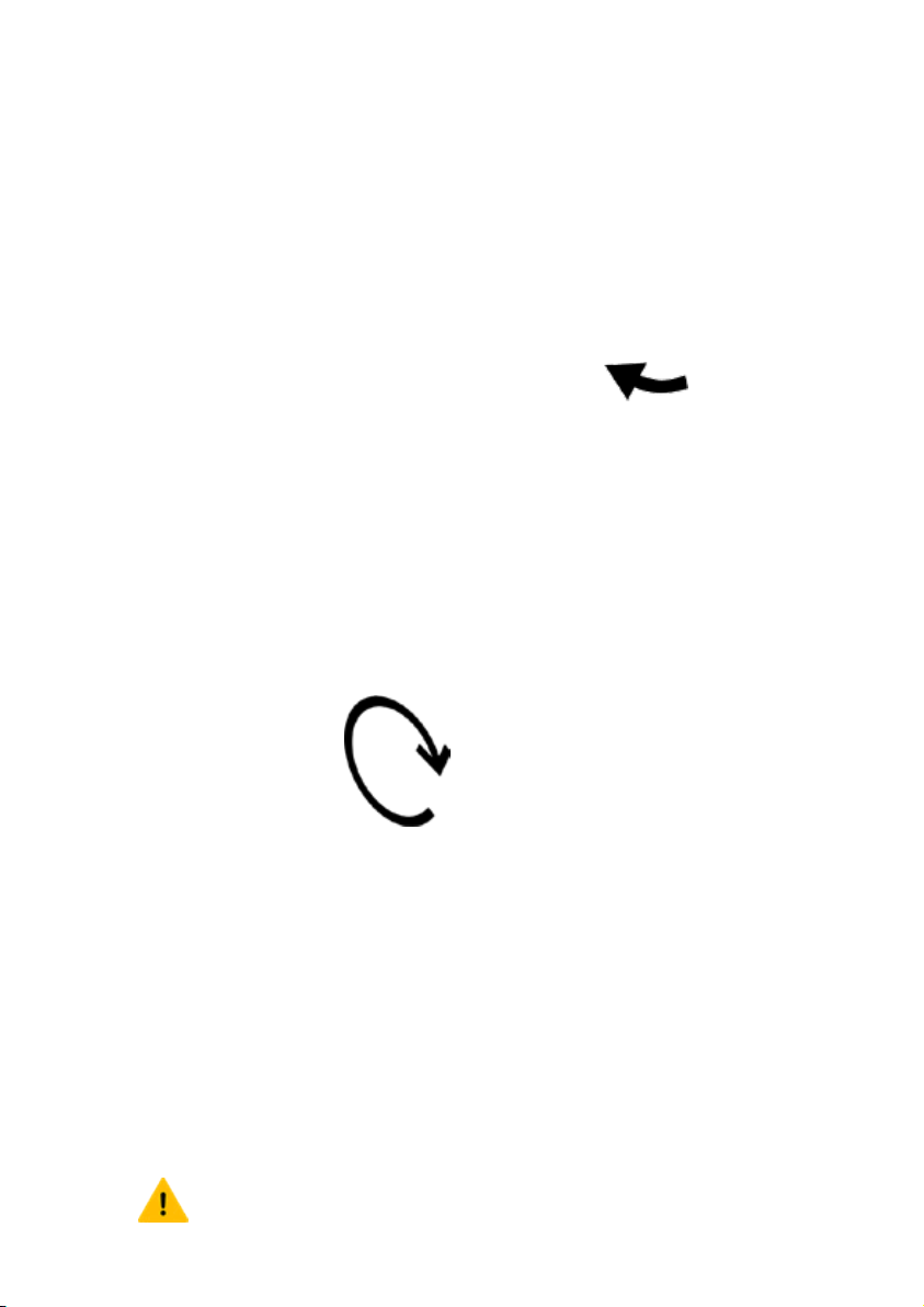
Step 5 Rotate Padel
(a)Press down on the pedals in the folded state to align the inner rotat
-ing structure
(b)Rotate the pedals to position as in the above picture
(c)After rotating to the position, the pedal will automatically rebound
and fix
(a)
(b)
(c)
13

Step 6 Install Seat
1.Open the seatpost quick-release lever.
2.Slide the seatpost in or out of the seat tube to a height appropriate for
your leg length and preference. Do not extend the seatpost beyond the
minimum insertion marking etched onto the seatpost (see the “Seat
post out TOO FAR” illustration).
3.Align the quick release clamp opening with the notch in the seat tube,
and close the quick-release lever fully. Clos- ing the lever should require
enough pressure that it leaves an imprint in your hand. When closed,
the seat should not move up, down, left, or right. If needed, adjust the
lever tension by turning the adjustment nut opposite the quick-release
lever.
4.Try out your seat fit, and repeat steps 1–3 if the seat position needs a bit
more adjusting.
DANGER: Overextending the seatpost can cause it to break or fall off
your bike, which will put you at very high risk of serious injury or
death. Avoid this danger by inserting your seatpost into the seat tube
far enough that the minimum insertion point is no longer visible.
14
1 32

Adjusting for comfort and safety
The following steps are critical for
your comfort and safety, and
must be performed before your
first bike ride. We recommend
that you consult a bike fitting
professional such as a certified,
reputable bike mechanic who
specializes in bike fit.
Adjusting the seat angle and horizontal position
Many riders will prefer the seat to be roughly parallel to the ground, with
its horizontal position in the middle of the range marked on the seat rails.
To change the angle and horizontal position of the seat:
1.Use a 6 mm Allen wrench to loosen (but do not remove) the seat adjust-
ment bolt on the clamp located underneath the seat.
2.Move the seat backwards or forwards and tilt to adjust the angle. Do not
exceed the limit markings etched into one of the seat rails, which show
how far you can safely move the seat forwards and backwards.
3.Ensure the top of the seat rail clamp is aligned directly over the bottom
of the clamp so that the seat adjustment bolt will clamp the seat rails
properly. Then, while holding the seat in the desired position, use a 6 mm
Allen wrench to tighten the seat adjustment bolt securely to the torque
value.
WARNING:A loose seat clamp or seat adjustment bolt can cause
loss of control, bike/property damage, serious injury, or death. Prior to
first use, be sure to tighten the seat clamp via the seat adjustment
bolt properly. Regularly check to make sure that the seat adjustment
bolt is properly tightened and the clamp is secure on the seat rails.
15

Adjusting the seat height
An ideal seat height for most
riders allows them to be comfort-
able and get the best pedalling
efficiency. When the rider is
seated, they should be able to
place the ball of their foot on the
pedal at its lowest position while
their leg is almost fully extended,
with the knee slightly bent. The
seat should never be so high that
the rider must rock side to side or
fully straighten their legs while
pedalling. And the seat must
never be pulled out so far that
the minimum insertion point is
above the seat tube.
Depending on a rider’s preference, ability, and amount of experience with
bike and ebike riding, lowering the seat so the rider can put one or both
feet on the ground without dismounting from the seat may offer a safer
and more comfortable experience while operating the bike.
16
Tools and recommended torque values
The tool sizing listed below is a general guide, but it is possible that the head of a particular
bolt on your bike may vary, requir- ing a different tool (e.g., a 4 mm Allen wrench instead of a
5 mm Allen wrench). If so, use whatever tool fits the bolt head. Such differences will not
affect the recommended torque for that piece of hardware.

17
Tool
Rec.
torque
Handlebar
area
Stem clamp bolts
5 mm Allen
10 Nm
Stem faceplate bolts
5 mm Allen
6
Nm
Stem angle adjustmentbolt
(side)
5 mm Allen
12 Nm
Stem angle adjustmentbolt
(bottom)
5 mm Allen
15 Nm
Rad UI Displayclamp bolts
3 mm Allen
3
Nm
Rad UI Remote clamp bolt
3 mm Allen
3
Nm
Shifter clamp bolt
Phillips or flat
head
6
Nm
Brake lever clamp bolts
5 mm Allen
6
Nm
Brake
area
Calliperadapter to frame
5 mm Allen
6–8
Nm
Calliper to adapter
5 mm Allen
6–8
Nm
Brake padsto calliper
Cotter
pin
n/a
Brake rotor to hub
T25 Torx bit 7
Nm
Seat
area
Seat adjustment bolt
6 mm Allen
15 Nm
Frame
downtube
Controller mounting bolts
3 mm Allen
3
Nm
Frame cable cover bolts
2.5mm Allen
tighten
securely;donot
overtighten
Rear dropout
area
Rear axle nuts
18 mm wrench
40 Nm
Torque arm bolt
4 mm Allen
5
Nm
Derailleur hanger mounting bolt
5 mm Allen
10Nm
Derailleur mounting bolt
5 mm Allen
10Nm
Derailleur cable clamp bolt
5 mm Allen
6–8
Nm
Bottom bracket
and crank area
Pedalinto crank arm
15mm pedal
wrench
35 Nm
Crank arm removal info
Crank pullerfor
squaretaper
bottom bracket
n/a
Crank arm bolt into bottom bracketspindle
8 mm Allen
35Nm
Freewheel removal information
Contact Rad
Power Bikes
Product
Sup-
port
n/a
Chainring
bolts
5 mm Allen
10Nm
Kickstand mounting bolts
5 mm Allen
8
Nm
Bottom bracket and cups
BBT-22 Park
Tool
60 Nm
Accessories
Headlight/front fender/mudguard mounting bolt
5mm Allenand
10 mm wrench
6
Nm

Insert the key to unlock the battery
Step 7 Battery Charging
It is possible to remove the battery for storage, transportation, security, or
as an option for charging. To remove the battery, follow these steps.
1.Place the key into the keyport and turn it to the unlocked position.
2.The battery lock will release the battery from the frame and lift it out of
the mount slightly.
3.Carefully lift the battery up, angling it away from and clearing the
terminal contacts (“3” in the illustration above).
4.Pull the battery out of the mount. Be careful not to drop or damage the
battery when it’s loose from the bike. Do not touch or bend the terminal
contacts.
18

CHECK CHARGE LEVEL
Please check the color of the indicator light on the charger. If it is red, it
means it is not fully charged. If the indicator light on the charger turns
green or turns off, it means the battery is fully charged.
Critical battery safety overview
·Protect the battery from impact damage. Do not drop the battery.
Ensure the battery is locked to the frame before riding.
·Protect the battery from water and corrosion damage. Never submerge
the battery in water. Allow rain to run off of the battery from top to
bottom as designed. Avoid salt water and deicing compounds, which are
very corrosive and can lead to damage and danger.
·Remove the key from the bike’s battery keyport before riding.
·Never open the battery housing or charger. There are no user-service-
able parts in either the battery or battery charger.
·Turn off the bike for maintenance. Before performing any bike mainte-
nance, bike cleaning, or part replacement, power off the bike and remove
the battery to prevent accidental motor activation. Also discharge any
remaining power in the elec- trical system by pressing the power button.
That will protect all of the electrical components.
TEMPERATURES FOR SAFE STORAGE, CHARGING,
AND USE
For safety and the best battery performance, please be aware of the
following:
·Avoid riding in extreme temperatures, above 45°C (113°F), whenever
possible.
·If you ride in extremely hot temperatures (above 45°C (113°F)), use low
levels of power assistance to keep the battery as cool as possible. This will
lower the risk of the battery automatically turning off to prevent
use-caused heat damage.
·Heat can cause the battery to automatically turn off.
·When the battery temperature reaches more than 60°C (140°F), the
battery is designed to turn off automatically to pre- vent use-caused heat
damage. When the battery cools enough, you should be able to turn your
battery back on.
19


