SM Pro Tube Box User manual

Tube Box
Operating Manual
August 2012

3
SAFETY INSTRUCTIONS
CAUTION: To reduce the risk of electrical shock, do not remove the cover or rear
panel of this unit. No user serviceable parts inside. Please refer servicing to qualied
personnel only.
WARNING: To reduce the risk of re or electrical shock do not expose this appliance
to rain or moisture.
DETAILED SAFETY INSTRUCTIONS:
All safety and operation instructions of this manual should be read and adhered to
before operation.
Retain Instructions:
Please retain all safety and operating instructions for future reference.
Follow instructions:
All operation and user instructions should be followed.
Water, liquid and Moisture:
The appliance should not be used near water, rain or other liquids. Make sure that
no liquid can leak, spill or otherwise seep into the appliance.
Ventilation:
Please place the appliance so no obstacles interfere or impede the ow of air through
the ventilation openings.
Heat:
The appliance should be situated away from other heat sources such as heaters,
radiators, ovens, or other appliances that produce heat.
Power Source:
Make sure your appliance is set to the correct voltage for the country in which it will
be use before switching the device ON.
Grounding and Polarization:
Precautions should be taken so that the grounding or polarization means of an ap-
pliance is not defeated.
Power-Cord Protection:
Power supply cords should be routed so that they are not likely to be walked on,
pinched, damaged, worn, or rubbed by any other device or obstacle.
Cleaning:
The appliance should be cleaned only with a light soft cloth. Do not use any dama-
ging or corrosive products on the unit.
Periods of inactivity:
The power cord of the appliance should be unplugged from the outlet when left un-
used for a long period of time or in case a lightning storm occurs.
Damage Requiring Service:
The appliance should be serviced by qualied service personnel when:
• The power supply cord or the plug has been damaged; or
• Objects have fallen, or liquid has been spilled into the appliance; or
• The appliance has been exposed to rain; or
• The appliance does not appear to operate normally or exhibits a marked change
in performance; or
• The appliance has been dropped, or the enclosure damaged.
Servicing:
The user should not attempt to service the appliance beyond that is described in the
Operating Instructions.
All other servicing should be referred to qualied service personnel.

4
FOREWORD
Dear Customer,
Thank you very much for expressing your condence in SM Pro Audio products by
purchasing this unit. The Tube Box has been designed to be used as a standard tool
for home/pro studios, P.A. rental companies, Schools and in many other situations
where audio products would be used. With much experience in the audio industry
over a long period of time, and along with valuable suggestions from our customers,
our engineers have developed a product we know you will be satised with. We
guarantee you uncompromising quality as well as excellent technical and audio pro-
perties at an extremely affordable price.
Regards,
SM Pro Audio
It should be pointed out, that extreme output volumes may damage your
ears and/or your headphone units. Turn down the LEVEL controls before you
switch on the unit.
PLACEMENT
The SM Pro Audio Tube Box has an electronic circuit inside as well as isolation
transformers. Be sure that there is enough air space around the unit for cooling.
As to avoid overheating, please do not place the units on high temperature devices
such as power ampliers or near other units which may have high frequency trans-
mittance such as wireless devices.
Mains voltage
The Tube Box should only be used with the correct power supply. It is compatible
with standard API lunch box systems as well as our own JUICE BOX series of pow-
er supplies. Please make sure you carefully read what the supply is rated for. Any
damage occurring as a result of incorrect voltage selection may not be granted a
warranty repair.

5
Tube Box Main Features
API lunchbox compatible version of our popular TC01 tube preamplier circuit.
• AN 6418 Electron Tube
• Tri color led for compression indication
• Low cut lter
• Switchable Phantom Power
• Switchable Phase Reversal
• Level display: Volume meter -20 dBu to +3 dBu
• Adjustable optical compressor
• Input gain control
• Switchable -20 dB Pad
• Housing: Metal
Ability to easily change opamps and bypass the tube circuit.
1. INTRODUCTION
In purchasing the new Tube Box, you have acquired a system 500
compatible tube mic/line preamp and optical compressor module.
The Tube Box is essentially a channel strip that meets many of the
demands of the home/pro studio. A tube microphone preamplier,
optical compression, Phantom power, phase reverse switch, low cut
switch , output volume control and metering, all packed in a conveni-
ent 500 series unit the Tube Box offers another layer of control and
sound which opens up the creative side of music . The Tube Box is
really 2 units in 1, giving you the unique sound of a tube preamplier
which on it’s own is a complete product, at the same time offering
you the smooth sound of an optical compressor. Don’t try to compa-
re the sound of this unit to any other on the market, it has it’s own
unique avor which is destined to become a classic in it’s own way.
The ability to bypass the tube and change the opamps give the
Tube Box the extra advantage of letting users decide what kind
of sound they like and opens up the possibility to modify the unit
in various ways. You will undoubtably see blogs and posts about
users getting a different sound from the Tube Box by changing
certain components, it’s a great way to experiment.
2. THE DESIGN CONCEPT
2.1 High quality components and design
The philosophy behind SM Pro Audio products guarantees a no-compromise circuit
design and employs the best choice of components.

6
3. Installation
Your SM Pro Audio Tube Box was carefully packed in the factory and the packaging
was designed to protect the unit from rough handling. Nevertheless, we recommend
that you carefully examine the packaging and its contents for any signs of physical
damage, which may have occurred in transit.
If the unit is damaged, please do not return it to us, but notify your dealer and the
shipping company immediately, otherwise claims for damage or replacement may
not be granted. Shipping claims must be made by the consignee.
Please check that the TUBE is in place and has not come out of it’s socket.
3.1 Connecting
The SM Pro Audio Tube Box is a standard 500 series module and as such you must
follow the correct connection diagram and use an appropriate power supply (such
as the SM Pro Audio ‘Juice Box’).
The Pinouts for 500 series modules can be found here:
Connector: 306-015-520-102EDAC type
Terminal: 1 CHASSIS
2 OUTPUT + (+4 Level)
3 Output + (-2 Level)
4 OUTPUT
5 GND
6 STEREO LINK
7 INPUT - (-2 Level)
8 INPUT - (+4 Level)
9 INPUT + (-2 Level)
10 INPUT + (+4 Level)
11 GAIN TRIM RESISTOR
12 +16V DC
13 GND
14 -16V DC
15 +48V DC
Optional SM Pro Audio
power supply

7
3.2 Audio Connections
The Tube Box features a 1/4” (6.5mm) TRS connector on the front panel for connec-
tion of a Balanced Microphone.
All other connections are done thru the back panel multipin connector.
* Note: The Tube Box accepts mic or line level input signals. Do not connect your
power amplier outputs to the Tube Box inputs!
3.3 Preamp control
The Tube Box features a Tube Amplier, the control for the pre-
amp are the INPUT GAIN, the PAD(-20dB) and the Phantom
power switch.
A Peak LED is also provided to indicate when the input level ex-
ceeds the preamps operational level and send the unit into square
wave (distortion) which sometimes may be a desirable effect.
3.4 optical compressor
3.4.1 Compression on/off switch & LED Indicator (nearthe
PEAK light)
Turns the compressor stage on or off. The indicator shows the on/
off status of the compressor as well as the compression amount,
it is a tri state LED.
3.4.2 Rotary compression control
The rotary compression control sets the compression ratio of the
compressor. The compression ratio expresses the difference between the input level
change and the output level change. A compression ratio of 6:1, for example, indi-
cates that for every 6dB of level change on the input signal there is only 1dB of level
change on the compressed signal. The higher the compression ratio, the smaller the
dynamic range.
3.4.3 Rotary attack encoder
The rotary attack control allows for adjustment in milliseconds the time it takes the
compressor module to respond to the corresponding input signal before gain re-
duction occurs. Short attack times quickly bring down the level of the loud, fast
transients in the audio signal; long attack times let more sound through before the
compressor engages, resulting in a punchier sound.
3.4.4 Rotary release encoder
The release control sets the time in seconds it takes for the compressor module gain
to return to the point of no gain reduction in the absence of audio program material.
Short release times create a more exaggerated effect („breathing“), whereas long
release times have a more gradual decay.
3.5 Output level
The output level basically does as it says, controls the output level of the TUBE BOX.
3.5.1 Phase reversal switch
A phase reverse switch is available for reversing the phase of the signal by 180 de-
grees. This can be desired in situations such as recording a snare drum from above

8
and below the drum simultaneously. By reversing the phase on one of your micro-
phone signals you will achieve a better result, recording full range of signal without
a phase cancellation occurring. It is also used for matching the rest of your gear or
recordings or removing feedback when recording stereo pairs.
3.5.2 80Hz low-cut (high-pass) lter switch
The low-cut (high-pass) lter switch enables and disables the 80Hz high-pass lter.
Engaging this lter effectively removes low frequency “rumble” and other unwanted
noise by attenuating the signal dB below 80Hz.
4. making sounD
Make your physical connections
Simply make your signal connections by either connecting an instrument (guitar,
bass,mic etc) to the instrument input on the front panel, or connecting an input to the
rear of a 500 series power supply box.
Do you need phantom power or to change the phase of your input signal?
If you are using a condenser microphone that requires phantom power, select the
phantom power switch to the on position. You can also choose to switch the polarity
of your signal at this stage if required.
Set your input gain control
Set your input level. Adjust the input rotary control to an acceptable level. This is
a good time to check the clip indicator to ensure you are not overdriving the tube
pre-amp with too much signal. If your signal is too strong, reduce the amount with
the rotary control. If you cannot reduce the signal enough to stop the clip indicator
constantly illuminating, you can enable the -20dB PAD to assist in reducing the in-
coming signal gain.
Do you desire compression?
You can now choose to add some optical compression to your signal if desired.
You can select the compressor on/off switch to the on position. Set your attack and
release pots to the desired settings, and adjust the compression ratio rotary control
until you are satised with the result.
Set your output level
Adjust your master output level rotary control to the required amount.
5. Let’s play
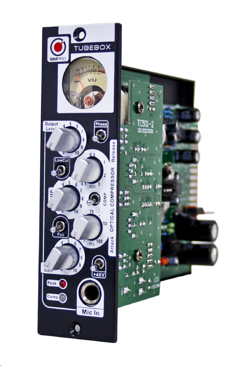
The Tube Box’s opamps are in DIP8 sockets, this simply means that users can
easily interchange between different types of opamps to achieve different results.
We use a combination of 5532 and 4580 in the Tube Box so feel free to change then
around and we would be happy if you report the results to us as well.
5.1 Line Input Level
Right next to the Tube, you will nd a Blue colored trimpot. This trimpot if for the
adjustment of the input level from the 500 series connector. To make the unit as
compatible as possible we left this as a variable resistor so that users can match the
level to their own system.
9
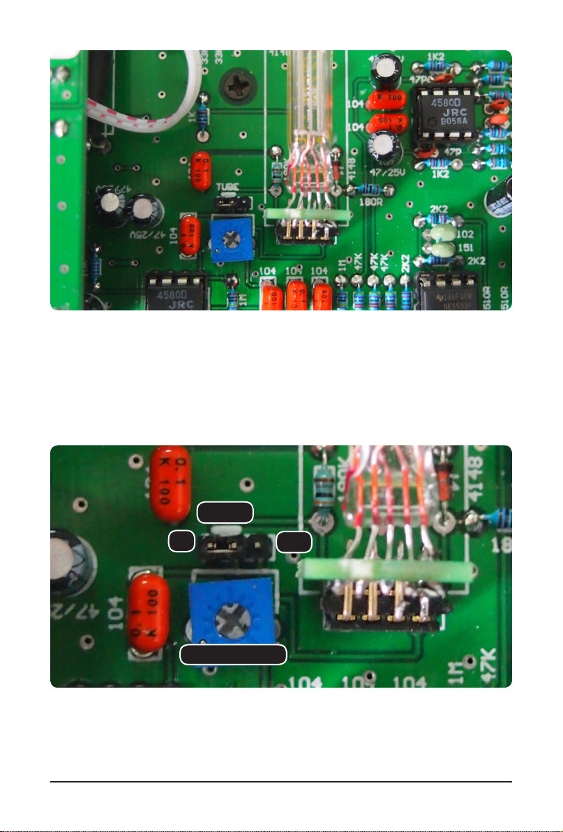
5.2 Tube Bypass
The Tube in the TUBE BOX can be exchanged to various compatible types, it is
tted on a connector so it is easily replaced. Near the Tube is small selector Pad,
you can bypass the tube section entirely and use the TUBE BOX purely as an optical
compressor.
The blue colored trimpot next to the tube
The small selector Pad to bybass the tube and the gain adjustment
Gain adjust
Tube
ON OFF

10
8. Warranty
8.1 Warranty Card
To be protected by this warranty, the buyer must complete and return the enc-
losed warranty card (signed/stamped by retail dealer) within 14 days of the date of
purchase to SM Pro Audio (see address below 3). Failure to return the card in due
time (date as per postmark) will void any extended warranty claims.
8.2 Warranty
8.2.1. SM Pro Audio warrants the mechanical and electronic components of this
product to be free of defects in material and workmanship for a period of one (3)
years from the original date of purchase, in accordance with the warranty regulati-
ons described below. If any defects occur within the specied warranty period that
are not caused by normal wear or inappropriate use, SM Pro Audio shall, at its sole
discretion, either repair or replace the product.
8.2.2. If the warranty claim proves to be justied, the product will be returned
freight prepaid by SM Pro Audio within Australia. Outside of Australia, the product
will be returned at the buyer‘s expense.
8.2.3. Warranty claims other than those indicated above are expressly excluded.
8.3 Return Authorization Number
8.3.1. To obtain warranty service, the buyer must call SM Pro Audio during normal
business hours BEFORE returning the product (Tel.: +61 3 9555 8081). All inqui-
ries must be accompanied by a description of the problem. SM Pro Audio will then
8.3.2. The product must be returned in its original shipping carton, together with the
return authorization number, to the following address:
SM Pro Audio
Service Department
W25, 26-28 Roberna St
Moorabbin
Melbourne, Victoria
Australia 3189

11
8.4 Warranty Regulations
8.4.1. Warranty services will be furnished only if the product is accompanied by an
original retail dealer‘s invoice. Any product deemed eligible for repair or replace-
ment by SM Pro Audio under the terms of this warranty will be repaired or replaced
in the best possible manner.
8.4.2. If the product needs to be modied or adapted in order to comply with
applicable technical or safety standards on a national or local level, in any country
which is not the country for which the product was originally developed and manu-
factured, this modication/adaptation shall not be considered a defect in materials
or workmanship.
The warranty does not cover any such modication/adaptation, irrespective of
whether it was carried out properly or not. Under the terms of this warranty, SM Pro
Audio shall not be held responsible for any cost resulting from such a modication/
adaptation.
8.4.3. Free inspections, maintenance/repair work and replacement of parts are
expressly excluded from this warranty, in particular if caused by inappropriate use.
Likewise, the warranty does not cover defects of expendable parts caused by
normal wear of the product. Expendable parts are typically pots, potentiometers,
switches and similar components.
8.4.4. Damages/defects caused by the following conditions are not covered by this
warranty:
• Misuse, neglect or failure to operate the unit in compliance with the instruc-
tions given in the user or service manuals.
• Connection or operation of the unit in any way that does not comply with the tech-
nical or safety regulations applicable in the country where the product is used.
• Damages/defects that are caused by any other condition beyond the control of
SM Pro Audio.
8.4.5. Any repair carried out by unauthorized personnel will void the warranty.
8.4.6. Products which do not meet the terms of this warranty will be repaired
exclusively at the buyer‘s expense. SM Pro Audio will inform the buyer of any such
circumstance. If the buyer fails to submit a written repair order within 4 weeks after
notication, SM Pro Audio will return the unit C.O.D. with a separate invoice for
freight and packing. Such cost will also be invoiced separately when the buyer has
sent in a written repair order.
8.5 Claim for Damages
Failure of SM Pro Audio to provide proper warranty service shall not entitle the
buyer to claim (consequential) damages. In no event shall the liability of SM Pro
Audio exceed the invoiced value of the product.
8.6 Other Warranty Rights
This warranty does not exclude or limit the buyer‘s statutory rights provided by
national law, in particular, any such rights against the seller that arise from a legally
effective purchase contract.
The information contained in this manual is subject to change without notice. No
part of this manual may be reproduced or transmitted in any form or by any means,
electronic or mechanical, including photocopying and recording of any kind, for any
purpose, without the express written permission of SM Pro Audio.

12
ALL RIGHTS RESERVED © 2012 SM Pro Audio
All illustrations, descriptions and technical specications are subject to
change without prior notice.
SM Pro Audio Service Department
W25, 26-28 Roberna St Moorabbin Melbourne, Victoria Australia 3189
www.smproaudio.com
Table of contents
Other SM Pro Amplifier manuals


