SMA SB5.0-1SP-US-40 User manual

SB5.0-1SP-US-40 / SB6.0-1SP-US-40
Replacing a Defective Power Unit
SB50-60-1SP-US-40-AT-PU-SG-xx-10 | 102509-00.01 | Version 1.0
ENGLISH Service Manual ESPAÑOL Instrucciones de servicio técnico
FRANÇAIS Manuel de service

Table of Contents
1 Safety Information.................................................................... 3
2 Overview of the Enclosure Parts ............................................. 4
3 Disconnecting the Inverter from Voltage Sources.................. 5
4 Disassembling the Defective Power Unit ................................ 7
5 Mounting the New Power Unit................................................ 10
6 Packaging the Defective Power Unit for Pick-Up................... 13
Table of Contents SMA Solar Technology America LLC
Service ManualSB50-60-1SP-US-40-AT-PU-SG-xx-102
ENGLISH

1 Safety Information
This section contains safety information that must be observed at all times when working on or with
the product.
To prevent personal injury and property damage and to ensure long-term operation of the product,
read this section carefully and observe all safety information at all times.
Danger to life due to high voltages in the inverter
When exposed to sunlight, the PV array generates dangerous DC voltage which is present in the
DC conductors and the live components of the inverter. Touching the DC conductors or the live
components can lead to lethal electric shocks.
• All work on the inverter must be carried out by qualified persons only. Qualified persons
must at least have the following skills:
– Knowledge of how SMA inverters work and are operated
– Training in how to deal with the dangers and risks associated with installing, repairing
and using electrical devices and installations
– Knowledge of how to safely disconnect SMA inverters
– Knowledge of all applicable laws, standards and directives
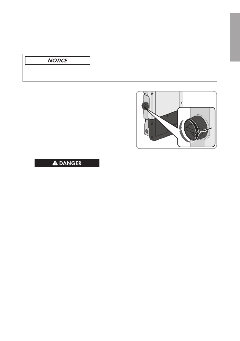
• Prior to performing any work on the inverter, disconnect it from all voltage sources as
described in this document (see Section3, page5).
• After disconnecting the inverter from voltage sources, a certain waiting time must be
observed to allow the residual voltages in the DC link of the inverter or in the charging circuit
of the capacitors to discharge. This waiting time is at least ten minutes.
• Do not touch any live components of the inverter.
Risk of burns from hot surfaces
The surface of the inverter can get very hot. Touching the surface can result in burns.
• Mount the inverter in such a way that it cannot be touched inadvertently.
• Do not touch hot surfaces.
• Wait 30 minutes for the surface to cool sufficiently.
• Observe the safety messages on the inverter.
Damage to the inverter due to electrostatic discharge
Touching electronic components can cause damage to or destroy the inverter through
electrostatic discharge.
• Ground yourself before touching any component.
1 Safety Information
SMA Solar Technology America LLC
Service Manual 3SB50-60-1SP-US-40-AT-PU-SG-xx-10
ENGLISH

2 Overview of the Enclosure Parts
Figure 1 : Overview of the enclosure parts
Position Designation
A Power Unit
B Connection Unit
2 Overview of the Enclosure Parts SMA Solar Technology America LLC
Service ManualSB50-60-1SP-US-40-AT-PU-SG-xx-104
ENGLISH

3 Disconnecting the Inverter from Voltage Sources
Prior to performing any work on the inverter, always disconnect it from all voltage sources as
described in this section. Always adhere to the prescribed sequence.
Destruction of the measuring device due to overvoltage
• Only use measuring devices with a DC input voltage range of 600V or higher.
1. Disconnect the AC circuit breaker and secure it against reconnection.
2. Set the DC load-break switch of the inverter to O
.
3. If the multifunction relay is used, switch off any supply voltage to the load.
4.
Danger to life due to high voltages on the DC-in connecting terminal plate
When exposed to sunlight, the PV array generates dangerous direct voltage. Touching the
DC conductors can lead to lethal electric shocks. Even if the DC load-break switch of the
inverter is in the O, position, there will be dangerous direct voltage present in the DC
conductors and on the DC-in connecting terminal plate in the Connection Unit.
• If an external DC disconnecting switch is available, open the external DC disconnecting
switch.
• If there is no external DC disconnecting switch, cover the PV modules with opaque
material (e.g. foil).
• Ensure that there is no voltage on the DC conductors of the PV array.
• Wait five minutes before working on the inverter.
• Leave the DC-in connecting terminal plate plugged into the Connection Unit and only
touch it on the black enclosure.
5. Wait until the LEDs have gone out.
6. Unscrew all six screws of the enclosure lid of the Connection Unit with a Torx screwdriver (TX
25) and remove the enclosure lid carefully toward the front. While doing so, note that the
display assembly on the enclosure lid and the communication assembly in the inverter are
connected via a ribbon cable.
3 Disconnecting the Inverter from Voltage Sources
SMA Solar Technology America LLC
Service Manual 5SB50-60-1SP-US-40-AT-PU-SG-xx-10
ENGLISH

7. Disconnect the display cable from the socket on
the communication assembly.
8. Use a current clamp to ensure that no current is present in the DC conductors.
9. Ensure there is no voltage on the AC-out connecting terminal plate between L1 and N and L2
and N using a suitable measuring device. To do this, stick the test probe (max. diameter: 2mm
(0.078in)) in each rectangular opening of the terminal.
10. Ensure there is no voltage on the AC-out connecting terminal plate between L1 and the
equipment grounding conductor and L2 and the equipment grounding conductor using a
suitable measuring device. To do this, stick the test probe (max. diameter: 2mm (0.078in)) in
each rectangular opening of the terminal.
3 Disconnecting the Inverter from Voltage Sources SMA Solar Technology America LLC
Service ManualSB50-60-1SP-US-40-AT-PU-SG-xx-106
ENGLISH

4 Disassembling the Defective Power Unit
Prior to disassembling the defective Power Unit, all connections between the Power Unit and the
Connection Unit must be severed. Only then can the Power Unit be removed from the Connection
Unit. All conductors connected to the communication assembly can remain plugged in and do not
need to be removed to disassemble the Power Unit.
Damage to the enclosure parts due to frost
• Do not disassemble the Power Unit unless the ambient temperature is at least 0°C (32°F)
and conditions are frost-free.
Damage to the Connection Unit due to moisture ingress
If no new Power Unit is immediately available, do not disassemble the Power Unit. As soon as the
Power Unit is disassembled, moisture can penetrate the Connection Unit.
• Only disassemble the defective Power Unit once the new Power Unit is ready and available.
Procedure:
1.
Danger to life due to high voltages
• Disconnect the inverter from all voltage sources (see Section3, page5).
2. Remove the connecting terminal plate with the
connected DC conductors from slot DC-in. To do
this, unscrew the screws using a flat-blade
screwdriver (blade width: 3.5mm (0.14in)) and
pull the connecting terminal plate out of the slot.
During this operation, only touch the connecting
terminal plate on the black enclosure.
3. Remove the connecting terminal plate with the
connected AC conductors from slot AC-out. To
do this, unscrew the screws using a flat-blade
screwdriver (blade width: 3.5mm (0.14in)) and
pull the connecting terminal plate out of the slot.
4 Disassembling the Defective Power Unit
SMA Solar Technology America LLC
Service Manual 7SB50-60-1SP-US-40-AT-PU-SG-xx-10
ENGLISH

4. If there is a switch and an outlet for secure
power supply operation connected, remove the
connecting terminal plate with the connected
cable from the SPS slot. To do this, unscrew the
screws using a flat-blade screwdriver (blade
width: 3.5mm (0.14in)) and pull the connecting
terminal plate out of the slot.
5. Pull the ribbon cable connecting the
communication assembly to the Power Unit out
of the communication assembly.
6. Lead the ribbon cable with plug back to the
COM slot in the Power Unit and insert the plug
into the slot until it is flush with the black plastic
of the slot.
7. If the inverter is fitted with a padlock for theft
protection, open the padlock and remove it.
8. Using a Torx screwdriver (TX 25), unscrew the
screw M5x60 which fastens the inverter to the
wall mounting bracket.
4 Disassembling the Defective Power Unit SMA Solar Technology America LLC
Service ManualSB50-60-1SP-US-40-AT-PU-SG-xx-108
ENGLISH

9. Release the two screws on the right and left side
of the Power Unit with a Torx screwdriver
(TX25) and retain together with the washers for
later use.
10. Lift to remove the Power Unit out of the wall
mounting bracket, thus separating the Power
Unit from the Connection Unit.
11. If necessary, remove residual insulation material
from the two connection openings at the top of
the Connection Unit.
4 Disassembling the Defective Power Unit
SMA Solar Technology America LLC
Service Manual 9SB50-60-1SP-US-40-AT-PU-SG-xx-10
ENGLISH

5 Mounting the New Power Unit
1.
Danger to life due to high voltages
• Disconnect the inverter from all voltage sources (see Section3, page5).
2. Hook the new Power Unit into the upper recesses of the wall mounting bracket, thus plugging
the Power Unit into the Connection Unit. Make sure that the screw holes on the left and right
sides of the Power Unit are directly over those of the Connection Unit.
3. Fasten two screws with washers on the right and left side of the Power Unit using a Torx
screwdriver (TX25) (torque: 6Nm ± 0.3Nm (53in-lb ± 2.65in-lb)).
4. Secure the inverter to the wall mounting bracket.
To do this, insert the screw M5x60 through the
hole on the left side of the Power Unit using a
Torx screwdriver (TX25) and screw it into the
thread (torque: 1.7Nm ± 0.3Nm (15.05in-lb
± 2.65in-lb)).
TOP
5. If the inverter is to be protected against theft, attach a padlock:
• To do this, guide the shackle of the padlock
through the provided hole on the left side of
the Power Unit and close the shackle.
TOP
• Keep the key of the padlock in a safe place.
6. Pull the ribbon cable used to connect the
communication assembly to the Power Unit out
of the Power Unit through the opening COM
into the Connection Unit, and plug it into the jack
on the communication assembly.
5 Mounting the New Power Unit SMA Solar Technology America LLC
Service ManualSB50-60-1SP-US-40-AT-PU-SG-xx-1010
ENGLISH

7. Plug the connecting terminal plate with the
connected DC conductors into slot DC-in in the
Connection Unit. While doing so, only touch the
connecting terminal plate on the black
enclosure.
8.
Danger to life due to electric arc
The connecting terminal plate must be fastened to the slot with two screws. If the connecting
terminal plate is not correctly mounted and comes out of the slot, an electric arc can form. An
electric arc can cause life-threatening injuries.
• Tighten the screws of the connecting
terminal plate using a flat-blade
screwdriver (blade width:3.5mm
(0.14in)) (torque: 0.3Nm(2.65in-lb)).
• Ensure that the connecting terminal plate is securely in place.
9. Plug the connecting terminal plate with the
connected AC conductors into the AC-out slot in
the Connection Unit, and tighten with a flat-
blade screwdriver (blade width: 3.5mm
(0.14in)) (torque 0.3Nm (2.65in-lb)).
5 Mounting the New Power Unit
SMA Solar Technology America LLC
Service Manual 11SB50-60-1SP-US-40-AT-PU-SG-xx-10
ENGLISH

10. If applicable, plug the connecting terminal plate
with the connected cable for secure power
supply operation into the SPS slot in the
Connection Unit, and tighten with a flat-blade
screwdriver (blade width: 3.5 mm (0.14 in))
(torque 0.3Nm (2.65in-lb)).
11. Commission the inverter (see inverter manual).
☑ Through the replacement of the Power Unit, the inverter has been assigned a new serial
number (see type label).
12. If the inverter is registered in Sunny Portal, replace the inverter in Sunny Portal (see installation
manual "Replacement of SMA Devices in Systems with Communication Products" at
www.SMA-Solar.com).
5 Mounting the New Power Unit SMA Solar Technology America LLC
Service ManualSB50-60-1SP-US-40-AT-PU-SG-xx-1012
ENGLISH

6 Packaging the Defective Power Unit for Pick-Up
1. Package the defective Power Unit for pick-up. Use the original packaging of the new Power
Unit for this purpose.
2. Arrange for pick-up by SMA. To do this, contact Service (refer to www.SMA-Solar.com for
contact details).
6 Packaging the Defective Power Unit for Pick-Up
SMA Solar Technology America LLC
Service Manual 13SB50-60-1SP-US-40-AT-PU-SG-xx-10
ENGLISH

Índice
1 Indicaciones de seguridad....................................................... 15
2 Imagen de las partes de la carcasa........................................ 17
3 Desconexión del inversor de la tensión.................................. 18
4 Desmontaje de la Power Unit averiada ................................. 20
5 Montaje de la nueva Power Unit ............................................ 23
6 Embalaje y recogida de la Power Unit averiada .................. 26
Índice SMA Solar Technology America LLC
Instrucciones de servicio técnicoSB50-60-1SP-US-40-AT-PU-SG-xx-1014
ESPAÑOL

1 Indicaciones de seguridad
Este capítulo contiene indicaciones de seguridad que deben observarse siempre en todos los
trabajos que se realizan en el producto y con el producto.
Para evitar las lesiones al usuario y los daños materiales y garantizar el funcionamiento
permanente del producto, lea detenidamente este capítulo y respete siempre las indicaciones de
seguridad.
Peligro de muerte por altas tensiones en el inversor
Cuando recibe luz solar, el generador fotovoltaico produce una tensión de CC peligrosa
presente en los conductores de CC y en los componentes conductores del inversor. El contacto
con los conductores de CC o los componentes conductores puede causar descargas eléctricas
mortales.
• Todos los trabajos en el inversor deben realizarlos exclusivamente especialistas, que han de
contar al menos con esta cualificación:
– Conocimientos sobre los procedimientos y el funcionamiento de inversores de SMA
– Formación sobre la gestión de peligros y riesgos relativos a la instalación, reparación y
manejo de equipos eléctricos y plantas
– Capacidad para desconectar los inversores de SMA de la tensión de manera segura
– Conocimiento de las leyes, normativas y directivas aplicables
• Antes de efectuar cualquier trabajo en el inversor, desconéctelo siempre de la tensión tal y
como se describe en este documento (consulte el capítulo3, página18).
• Una vez desconectado el inversor, es necesario esperar un tiempo determinado para que
se descargue la tensión residual del circuito intermedio del inversor o del circuito de carga
de los condensadores. El tiempo de espera debe ser como mínimo de 10minutos.
• No toque ningún componente bajo tensión del inversor.
Peligro de quemaduras por superficies calientes
La superficie del inversor puede calentarse mucho. Si se toca la superficie, podrían producirse
quemaduras.
• Monte el inversor de manera que no sea posible un contacto accidental con la carcasa.
• No toque la superficie caliente.
• Espere 30 minutos hasta que la superficie se haya enfriado lo suficiente.
• Tenga en cuenta las advertencias del inversor.
1 Indicaciones de seguridad
SMA Solar Technology America LLC
Instrucciones de servicio técnico 15SB50-60-1SP-US-40-AT-PU-SG-xx-10
ESPAÑOL

Daños en el inversor por descarga electrostática
Si toca componentes electrónicos, puede dañar o destruir el inversor debido a una descarga
electrostática.
• Póngase a tierra antes de tocar cualquier componente.
1 Indicaciones de seguridad SMA Solar Technology America LLC
Instrucciones de servicio técnicoSB50-60-1SP-US-40-AT-PU-SG-xx-1016
ESPAÑOL

2 Imagen de las partes de la carcasa
Imagen 2 : Imagen de las partes de la carcasa
Posición Denominación
A Power Unit
B Connection Unit
2 Imagen de las partes de la carcasa
SMA Solar Technology America LLC
Instrucciones de servicio técnico 17SB50-60-1SP-US-40-AT-PU-SG-xx-10
ESPAÑOL

3 Desconexión del inversor de la tensión
Antes de efectuar cualquier trabajo en el inversor, desconéctelo siempre de la tensión tal y como
se describe en este capítulo. Siga siempre el orden indicado.
Daños irreparables en el equipo de medición a causa de la sobretensión
• Use solo equipos de medición con un rango de tensión de entrada de CC de hasta 600 V
como mínimo.
1. Desconecte el disyuntor de CA y asegúrelo contra cualquier reconexión.
2. Coloque el interruptor-seccionador de potencia
de CC del inversor en la posición O.
3. Si se utiliza el relé multifunción, desconecte en caso necesario la tensión de alimentación del
equipo consumidor.
4.
Peligro de muerte por altas tensiones en la caja de bornes DC-in
Cuando recibe luz, el generador fotovoltaico produce una tensión de CC peligrosa. El
contacto con dichos conductores de CC puede causar descargas eléctricas mortales. Incluso
si el interruptor-seccionador de potencia de CC del inversor está en la posición O, una
tensión de CC peligrosa se acopla a los conductores de CC y a la caja de bornes DC-in de
la Connection Unit.
• Si hay un seccionador de CC externo, ábralo.
• Si no hay ningún seccionador de CC externo, cubra los módulos fotovoltaicos con
material opaco (por ejemplo, un plástico).
• Asegúrese de que no haya tensión en los conductores de CC del generador
fotovoltaico.
• Antes de trabajar en el inversor, espere 5minutos.
• Deje la caja de bornes DC-in enchufada en la Connection Unit y tóquela únicamente
por la carcasa negra.
5. Espere hasta que los leds estén apagados.
6. Suelte los seis tornillos de la tapa de la carcasa de la Connection Unit con un destornillador
Torx (TX25) y retire la tapa de la carcasa con cuidado tirando de ella hacia delante. Al
hacerlo, tenga en cuenta que el subgrupo de la pantalla en la tapa de la carcasa y el
subgrupo de comunicación del inversor están conectados por medio de un cable plano.
3 Desconexión del inversor de la tensión SMA Solar Technology America LLC
Instrucciones de servicio técnicoSB50-60-1SP-US-40-AT-PU-SG-xx-1018
ESPAÑOL

7. Extraiga el cable de la pantalla del conector
hembra en el subgrupo de comunicación.
8. Con una pinza amperimétrica, compruebe que no haya corriente en ninguno de los
conductores deCC.
9. Compruebe con un equipo de medición adecuado que no haya tensión en la caja de bornes
AC-out entre L1 y N y L2 y N. Para ello, introduzca la punta de comprobación (diámetro:
máximo 2mm [0,078 in]) en el agujero cuadrado del borne.
10. Compruebe con un equipo de medición adecuado que no haya tensión en la caja de bornes
AC-out entre L1 y el conductor de puesta a tierra del equipo y entre L2 y el conductor de
puesta a tierra del equipo. Para ello, introduzca la punta de comprobación (diámetro:
máximo 2mm [0,078 in]) en el agujero cuadrado del borne.
3 Desconexión del inversor de la tensión
SMA Solar Technology America LLC
Instrucciones de servicio técnico 19SB50-60-1SP-US-40-AT-PU-SG-xx-10
ESPAÑOL

4 Desmontaje de la Power Unit averiada
Para desmontar la Power Unit averiada, primero es necesario desconectar todas las conexiones
entre la Power Unit y la Connection Unit. A continuación, puede desmontarse la Power Unit de la
Connection Unit. Todos los conductores que están conectados al subgrupo de comunicación
pueden permanecer insertados y no es necesario que se retiren para desmontar la Power Unit.
Daños por congelación en las piezas de la carcasa
• Desmonte la Power Unit solamente si la temperatura ambiente es de al menos 0°C (32°F)
y no hay heladas.
Daños en la Connection Unit por penetración de humedad
La Power Unit no debe desmontarse si todavía no está disponible una Power Unit nueva. Cuando
la Power Unit está desmontada puede penetrar humedad en la Connection Unit.
• Desmonte la Power Unit averiada solamente cuando esté disponible la nueva Power Unit.
Procedimiento:
1.
Peligro de muerte por altas tensiones
• Desconecte el inversor de la tensión (consulte el capítulo3, página18).
2. Retire de la ranura DC-in la caja de bornes con
los conductores de CC conectados. Para ello,
desenrosque los tornillos con un destornillador
plano (hoja: 3,5mm (0,14in)) y extraiga la
caja de bornes de la ranura. Toque únicamente
la carcasa negra de la caja de bornes.
3. Retire de la ranura AC-out la caja de bornes
con los conductores de CA conectados. Para
ello, desenrosque los tornillos con un
destornillador plano (hoja: 3,5mm (0,14in)) y
extraiga la caja de bornes de la ranura.
4 Desmontaje de la Power Unit averiada SMA Solar Technology America LLC
Instrucciones de servicio técnicoSB50-60-1SP-US-40-AT-PU-SG-xx-1020
ESPAÑOL
This manual suits for next models
1
Table of contents
Languages:
Other SMA Portable Generator manuals
Popular Portable Generator manuals by other brands

VOLTCRAFT
VOLTCRAFT HPS-11530 operating instructions

Black Max
Black Max BM905530 Quick reference guide

Siemens
Siemens SINAMICS S120 Equipment manual

Baumer
Baumer APY Mounting and operating instructions

Rigol
Rigol DSG3000B Series user guide

Generac Portable Products
Generac Portable Products iQ2000 owner's manual