Smach EFE 1500 User manual

SOFT-SERVE AND FROZEN YOGHURT FREEZER
SERVICE MANUAL
(SERVICE MANUAL)
for
MODEL: EFE 1500
Manual Number: V
001
-
17.05.2012

2
TABLE OF CONTENTS
1) Expansion Valve Adjustment
2) Refrigeration System Schematic
3) Control Functions
4) Air Adjustment
5) Electrical System
6) Troubleshooting (General, Inverter)
7) Inverter Control by a Laptop
8) Bacteria Troubleshooting
9) Exploded Views
3
1. EXPANSION VALVE ADJUSTMENT
Adjust the pressure higher or lower by turning the expansion valve adjustment screw. Clockwise turns will raise the
pressure and counterclockwise will lower the pressure.Bear in mind that In this model 3 0° turning is enough.
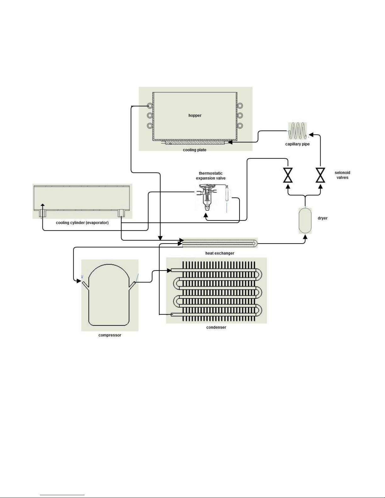
2. REFRIGIRATION SYSTEM SCHEMATIC

4
3. CONTROL FUNCTIONS
Stop
Machine operates keeping the temperature of the mix in the tankaround 4C. Therefore compressor runs at this
mode if the temperature is not mentioned above.
Wash
Machine operates cooling the mix in the tank and beater turns to blend the mix in the cylinder. Beater runs just
because to take the mix out of the cylinder in a short time.
Standby
Machine operates keeping the temperature of the mix in the tank and cylinder around 4C.
Soft&Hard
Machine operates keeping the temperature of the mix in the tank around 4C. Moreover, it cools down the mix in the
cylinder around - C when beater turns. Machine checks the current in the beater motor by an inverter when the
current is around 2. Amp for soft mode 2.8 Amp for hard mode, it stops cooling in the cylinder. However, beater
turns and cooling in cylinder starts if the motion sensor is activated by showing anything in front of them. This is
done normally when ice-cream is needed to dispense for serving. Otherwise, inverter tracks the time for 5 minutes
and then cooling in the cylinder starts and beater turns again. This goes on repeatedly. As it can be seen, soft and
hard modes are for turning the mix into ice-cream to be served. When the temperature in the cylinder goes down
the current need of the beater motor is increased.

5
4. AIR ADJUSTMENT
The AERATION TUBE has two parts ―OUTER and INNER
The OUTER has a large hole TOP and BOTTOM (These are constant)
The INNER tube has 3 different size holes TOP and BOTTOM
The INNER is turned inside the OUTER to select SMALL, MEDIUM or LARGE
The selection of the correct INNER hole-size depends on the product that is run through the Soft-Serve
Freezer and what amount of aeration is desired.
The setting can be changed during operations by simply turning the INNER aeration tube to the desired
size hole.
The SMALL HOLE will increase air percentage in the Soft-Serve and yield higher overrun.
The MEDIUM HOLE will result in an average air percentage and yield a medium overrun.
The LARGE HOLE for will decrease the air percentage and yield a lower overrun.
The LARGE HOLE setting may also be required for high-viscosity (thick) liquid mixes
TOP LARGE INNER TOP MEDIUM INNER TOP SMALL INNER
BOTTOM LARGE INNER BOTTOM MEDIUM INNER
BOTTOM SMALL INNER

5. ELECTRICAL SYSTEM

7
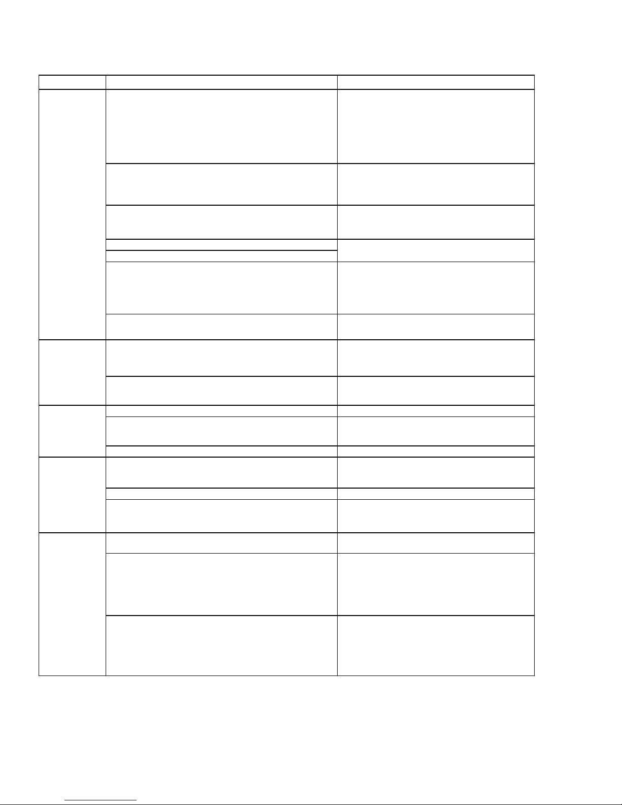
6.TROUBLESHOOTING
6.1. General
Troubleshooting
Problem CAUSE Solution
1 Machine does not run
Burnt Fuse Check&Replace.
Machine Unplugged Check&Plug the Machine
Selector mode is wrong Set the selector one of the soft-medium-hard
modes
2 Compressor starts then stops
after few seconds without
Air Not circulating Clereances should be 50 cm.
3 Machine fails to Cut-off when
running on ice cream
modes(soft-medium-hard)
Air circulation restricted Clereances should be 50 cm.
Too much air in cylinder Open tap&take off 1/2 litre of ice cream
No mix in Hopper(tank)or
just froth
Pour fresh mix
4 Machine works but no ice
cream comes out of tap
Frozen water in
spigot(piston)
All to thaw and take out 1 lt of mix/ice cream
before starting
No enough sugar in mix Replace with proper mix
5 Machine runs but ice cream
is too soft
Too much sugar in mix Replace with proper mix
Machine remained idle
without dispensing ice cream
Take out ice cream untill fresh mix is filled in
cylinder
Ice cream dispensed is too
fast
Do not exceed the production shown in the
capacity
6 Mix or ice cream comes out
from below or above the
closed tap/piston
Piston o-ring missing Putt the o-ring on piston
Piston with ruined o-ring Replace the o-ring with a new one
7 Mix comes from union drain Beater seal missing Put the beater seal
Beater seal ruined Replace the beater seal
8 Ice cream does not come out
of central tap
Cylinder(s) empty Add fresh mix
Too much air in cylinder(s) Add fresh mix
Ice cream frozen Run the machine on cleaning mode so that
frozen ice
cream will be melt
9 Ice cream comes out from
front lid/spigot
O-ring missing or not placed
properly
Place O-ring properly
Front knobs not tightened
properly/evenly
Tighten knobs evenlyand properly
10 Ice cream not increased
much in volume(overrun)
O-rings leaking Check and Replace, if necessary O Rings of
Pipe
Tighten knobs evenly
Improper mix Refill with proper mix(Proper fat&sugar)

8
6.2.Inverter Troubleshooting
*Description of Terminals Troubleshooting in erter
SYMBOL
R\L1(L)
S\L2
T / L3 ( N )
P1
BR
P1/ P
U / T1
V / T2
W / T3
SYMBOL
R2A
R2B
R1C
Common contact
R1B
Normal close contact
R1A
Normal open contact
10V
AIN
24V
COM
FM+
SYMBOL
S1
S2
S3
S4
S5
S
Description
Main power input Single-phase: L/N
Braking resistor or connecting termina l: Used in cases where the inverter
frequently disconnects due to large load inertia or short deceleration time
(refer to specifications of braking resistor)
For
220V:1HP
DC rea ctor connecting terminals (bridging connection P1 – P must be
removed for connecting an DC rea ctor)
Inverter outputs
Description of Terminals of Tro bleshooting Inverter
Descriptions of main circ it terminals
Descriptions of SW f nction
Frequency knob (VR = Potentiometer ), when operating with optional LED keypad
power source terminal (pin 3) LEVEL SENSOR,ALARM BUZZER
Analog frequency signal input terminal or multifunction input terminals S7 (H
level:>8V, L level:<2V, PNP only) LEVEL SENSOR
Common contact for S1~S5 (S , S7)in PNP (Source) input. Short-circuit pin 2 and pin
3 (refer to SYNPLUS wiring diagram) of SW1 when used PNP input Rotary switch,optical sensor
Descriptions of SYNPLUS control circ it terminals
Description
Multifunctional terminal – Normal open ALARM BUZZER
L
Multifunctional output
terminals
HOPPER DIGITAL THERMOSTAT
CYLINDER VALVE
Common contact and analog input /output signal for S1~S5in NPN (Sink) input.
Short-circuit pin 2 and pin 3 (refer to SYNPLUS wiring diagram) of SW1 when used
NPN input optical sensor,ssr,alarm buzzer
The positive analog output for multifunction (refer to 8-00 description), the signal for
output terminal is 0-10VDC (below 2mA). SSR
Function Description
Multifunction input terminals(refer to 5-00 ~ 5-04 description)
(S5 = Encoder input terminal for integrated PLC functionality, the Encoder voltage
range: 19.2V~24.7V)
Wash-rotary switch 1
Stand by-rotary switch 2
Soft-rotary switch 3
Hard-rotary switch 4
optical sensor
Multifunction input terminals ( Digital terminal H level:>8V, L level:<2V, PNP only)
o r analog input terminal A I 2 ( 0 ~ 1 0 V d c / 4 ~ 2 0 m A ) ( refer to 5-05 description)

9
Display
CPF
EPR
-OV-
-LV-
OH
Display
OC-S
OC-D
OC-A
OC-C
OV-C
Err4
OVSP
Error Ca se Remendy
PROGRAM PROBLEM External noise interference
Connect a parallel RC burst
absorber across the magnetizing
coil of the magnetic conta ctor
that causes interference
Voltage too low
during stop
1. Power voltage too low
2. Restraining resistor or fuse
burnt out.
3. Detection circuit
malfunctions
1. Check if the power voltage
was correct or not
2. Replace the restraining
resistor or the fuse
3. Send the inverter back for
The inverter is
overheated
during stop
1. Detection circuit
malfunctions
2. Ambient temperature too high
or bad ventilation
1. Send the inverter back for
repairing
2. Improve ventilation
conditions
EEPROM
problem Faulty EEPROM Replace EEPROM
Voltage too high
during stop Detection circuit malfunction Send the inverter back for
repairing
Over current at
start
1. the motor wind and
enclosure short circuit
2. the motor contacts and earth
short circuit
3. the IGBT module ruined
1.inspect the motor
2.inspect the wire
3.replace the transistor module
Over-current at
deceleration
The preset deceleration time is
too short. Set a longer deceleration time
Errors which can be recovered man ally and a tomatically
Error Ca se Remendy
Voltage too high
during operation/
deceleration
1. Deceleration time setting too
short or large load inertia
2. Power voltage varies widely
1. Set a longer deceleration time
2. Add a brake resistor or brake
module
3. Add a reactor at the power input
side
4. Increase inverter capacity
Illegal interrupt
of CPU Outside noise interference Send back to repair if it happens
many times
Over-current at
acceleration
1. Acceleration time too short
2. The capacity of the
motor higher than the
capacity of the inverter
3. Short circuit between
the motor coil and the
shell
4. Short circuit between
motor wiring and earth
5. IGBT module damaged
1. Set a longer acceleration time
2. Replace a inverter with the
same capacity as that of the
motor
3. Check the motor
4. Check the wiring
5. Replace the IGBT module
Over-current at
fixed speed
1. Transient load change
2. Transient power change
1.Increase the capacity of the
inverter
2.Rerun parameter auto tuning
(0-0 = 1)
3. Reduce stator resistance (14-0)
if the above remedies are
helpless
Over speed during
operating
1. Motor load too big or Inverter
capacity too small
2. Motor parameter error
(vector mode)
3. The gain is too big during
vector mode operating
4. The Current detect circuit
fault
1. Increase acceleration /
deceleration time (3-02/3-03)
2. Input correct motor
Parameter
3.Cha nge stator Resistance gain
and Rotator resistance gain
(14-0/14-1), suggest tha t
decrease 50~100, until 0
4. Send back to SMACH.
Errors which can not be recovered man ally
*Error display and remedy
*Error which cannot reco ered manually

10
Display
OC
OL1
OL2
OL3
LV-C
OH-C
Voltage too l ow
during operation
1. Powe r volta ge too low
2. Power volta ge varies wi del y
1. Improve power qua l ity or
increa s e the val ue of 2-01
2. Set a l onger accelerati on time
3. Increas e i nve rter ca pa citor
4. Add a reactor a t the powe r
input
s i de
Hea tsi nk
temperature
too High during
operation
1. Hea vy l oa d
2. Ambi ent temperature too
high or ba d venti l a tion
1. Check if there a re a ny
problems wi th the loa d
2. Increa s e inverter capa city
3. Improve venti l a tion
conditi ons
Inverter overloa d Hea vy Loa d Increa se the inverter capaci ty
Over torque
1. Hea vy Loa d
2. Ins uffi cient s ettings of 9-14,
9-15
1. Increa s e the i nverter capa city
2. s e t 9-14, 9-15 properly
Over-current during
s top
1. Detecti on ci rcui t
ma l functi ons
2. Ba d conne ction for CT
si gna l cable
1.Check the noi s e between Power
l i ne and motor l i ne
2.Send the inverter ba ck for
rep ai ri ng
Motor overloa d
1. Hea vy l oa d
2. I nappropriate setti ngs of
0-02, 9-08~11
1. Increa s e the motor capaci ty
2. s e t 0-02, 9-08~11 properly
Errors which can be recovered man ally
Error Ca se Remendy

11
Display
STP0
STP1
STP2
E.S.
b.b.
ATER
PDER
Auto-tuni ng fa ults 1. Motor data error res ulti ng i n for a uto-tuni ng fai lure
2. Stop the i nverter emergently duri ng Auto-tuning
PID fe edback loss PID fe edba ck loss detect
Keypa d
emergency s top
1. If the inverter is s et a s externa l control mode (1-00=0001) a nd Stop
key i s ena bl ed (1-03=0000), the inverter will s top according to the
setting of 1-05 when Stop key i s press ed. STP2 fl a s hes after s top.
Turn the operati on s wi tch to OFF a nd then ON a gain to res tart the
inverter.
2. If the inverter i s i n communi cati on mode a nd Stop key is enabl e d (1-
03=0000), the inverter wi l l s top i n the wa y s et by 1-05 when Stop
key i s press ed during operation and then fl a s hes STP2. The PC has
to s end a Stop command then a Run comma nd to the inverter for it to
be restarted.
3. Stop ke y cannot perform emergency s top when 1-03=0001
Externa l
emergency s top
The inverter wi l l ramp stop a nd the n fla s h E.S., whe n i nput external
emergency s top s igna l via the mul ti functi ona l i nput termi na l (refer to
des cripti ons of 5-00~5-0 ).
Externa l ba s e
bl ock
The inverter s tops i mmedia tel y and then fl as hes b.b., when externa l
ba se block i s input through the mul ti functi ona l i nput termi na l (refer
to des cripti ons of 5-00~5-0 ).
Special conditions
Error DESCRIPTION
Zero s peed s top Ha ppene d when pres et frequency <0.1Hz
Fail to sta rt di rectly
1. If the inverter is s et a s externa l termina l control mode (1-00=1) a nd
di rect sta rt i s dis a bled (2-04=0001), the i nverter ca nnot be s tarted
and will fl a sh STP1 when ope ration s witch turned to ON after
appl ying powe r (refer to de s cripti ons of 2-04).
2. Direct s ta rt is pos s i bl e when 2-04=0001.
*Special Condition

12
Display
LOC
Err1
Err2
Err5
Err
Err7
Err8
EPr1
EPr2
Parameter a nd
frequency
reverse a l ready
locked
1.Attempt to modi fy frequency
/pa rameter whil e 3-17>0000
2.Attempt to revers e whil e 1-02=0001
1.Set 3-17=0000
2. Set 1-02=0000
Key
operati on error
1.Pres s _ or _whil e 1-0 >0 or
runni ng a t pres et s pe ed.
2.Attempt to modi fy the pa ra meter can
not be modi fied during ope rati on
(refer to the parameter l i st).
1.The _ or_ i s avai labl e
for modifyi ng the
pa rameter onl y when
1-0 =0
2.Modify the pa rame ter
whi l e STOP
Operation errors
Error Ca se Remendy
Communi ca ti on
fai l ed
1.Wi ring error
2 .Communi cati on pa rameter s etting
error.
3.Sum-check e rror
4.Incorre ct communica ti on protocol
1.Check ha rdwa rea nd wiring
2.Check Functi on 13-1~13-4
Para meter
confl i ct
1.Attempt to modi fy the function 15-0
or 15-7
2.Vol tage a nd current detecti on circui t
is a bnorma l
If Res et inverter i s not
avai l a ble, plea se send the
inverter ba ck for repai r
Paramete r s etting
error
1. 3-01in the range of 3-13 ± 3-1 or
3-14 ± 3-1 or 3-15 ± 3-1
2. 3-00≤3-01
3.The s etting e rror a s performing Auto
tuning(e.g. 1-00 ≠ 0_1-0 ≠ 0 )
1.Modify 3-13~3-15or 3-1
2. 3-00>3-01Set 1-00=0, 1-
0 =0 during Auto tuning
Modi fica ti on of
pa rame ter i s
not a vai la bl e i n
communicati on
1.Is sue a control comma nd during
communicati on di s abled
2.Modify the function 13-1~13-4
during communi ca tion
1.Iss ue ena ble command
before communicati on
2.Set the very pa rameter
of thefuncti onbefore
communication
Parameter not
match
Copy the para meter to inverter to
verify the pa rameter i s not ma tch.
1.Rewrite a gain
2.Repl a ce copy unit
Factory s etti ng
error
When PLC i s Runni ng, Perform
factory s etti ng
Plea s e perform factory
s etti ng be fore PLC s tops .
Paramete r s etting
error copy uni t
fai l ed
1.Set 3-18=1.2 wi thout connecting
copy uni t.
2. Copy uni t fa i l ed.
1.Modi fy 3-18
2.Repl a ce copy unit
*Operation Errors
13
Stat s
General tro bleshooting
Checking point
Remedy
• Is a na l og frequency i nput s ignal wiri ng
correct?
• Is volta ge of frequency input correct?
Is operati on mode s etti ng correct?
• Opera te ope rati ons through the digital
pa ne l.
Motor runs
inversel y
Are wi ring for output termi nal s T1, T2, a nd T3
correct?
• Wi ring must match U, V, and W termi nal s of the
motor.
Are wi ring for forwa rd and reverse s ignal s
correct? • Check wiri ng a re correct if necess a ry.
Motor ca n not
run
Is power appl i ed to L1(L), L2, a nd L3(N)
termi nal s (is the cha rgi ng i ndica tor l i t)?
• Is the power appl ied?
• Turn the power OFF a nd then ON
aga i n.
• Make sure the power voltage is correct.
• Make sure s crews a re s ecured fi rmly.
Are there volta ge acros s the output termi na l
T1, T2, a nd T3?
• Turn the power OFF a nd then ON aga in.
Is overload ca usi ng the motor blocked?
• Reduce the load to l et the motor
running.
Are there any a bnormal i ti es i n the i nve rter?
• See error des criptions to check wiring
a nd correct if neces s ary.
Is forward or reverse runni ng comma nd i s s ued?
Motor s peed
varie s
unus ual l y
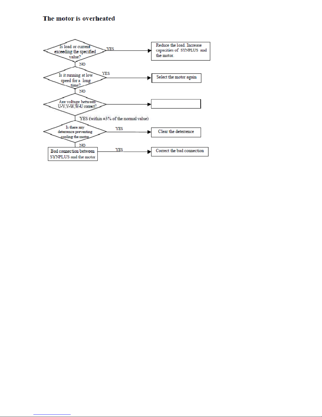
Is the l oad too hea vy? • Reduce the loa d.
Does the l oad va ry l a rgel y?
• Mi ni mi ze the variati on of the l oad.
• Increas e ca pa citi es of the inverter a nd
the motor.
Is the i nput power l a ck of pha s e?
• Add a n AC rea ctor a t the power i nput
side if us ing si ngl e-phase power.
• Check wiri ng if us ing three-phas e
power.
Motor
running
spee d too
hi gh or too
low
Are s pecifi cati ons of the motor (pol es ,
voltage…) correct? • Confi rm the motor’s s peci fica ti ons.
Is the ge ar ratio correct? • Confi rm the gea r ra tio.
Is the s etti ng of the hi ghes t output frequency
correct? • Confirm the hi ghest output frequency.
The motor
spee d can
not be
regul ate d.
Are wi ring for a na log frequency i nputs correct? • Check wiri ng are correct if necess a ry.
Is the s etti ng of operation mode correct? • Check the operation mode of the
operator.
Is the l oad too hea vy? • Reduce the loa d.
Has a na log frequency s ignal been input?
*General Troubleshooting of In erter
14
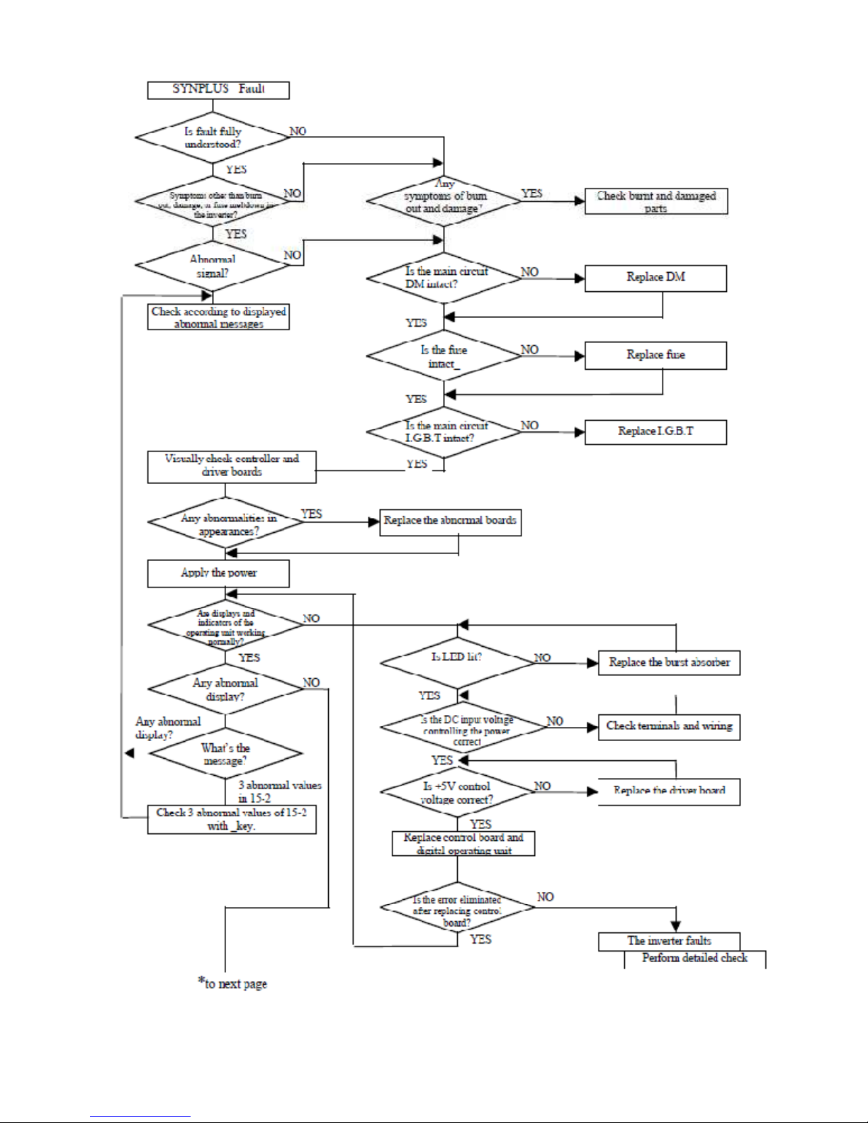
*Quick Troubleshooting of In erter
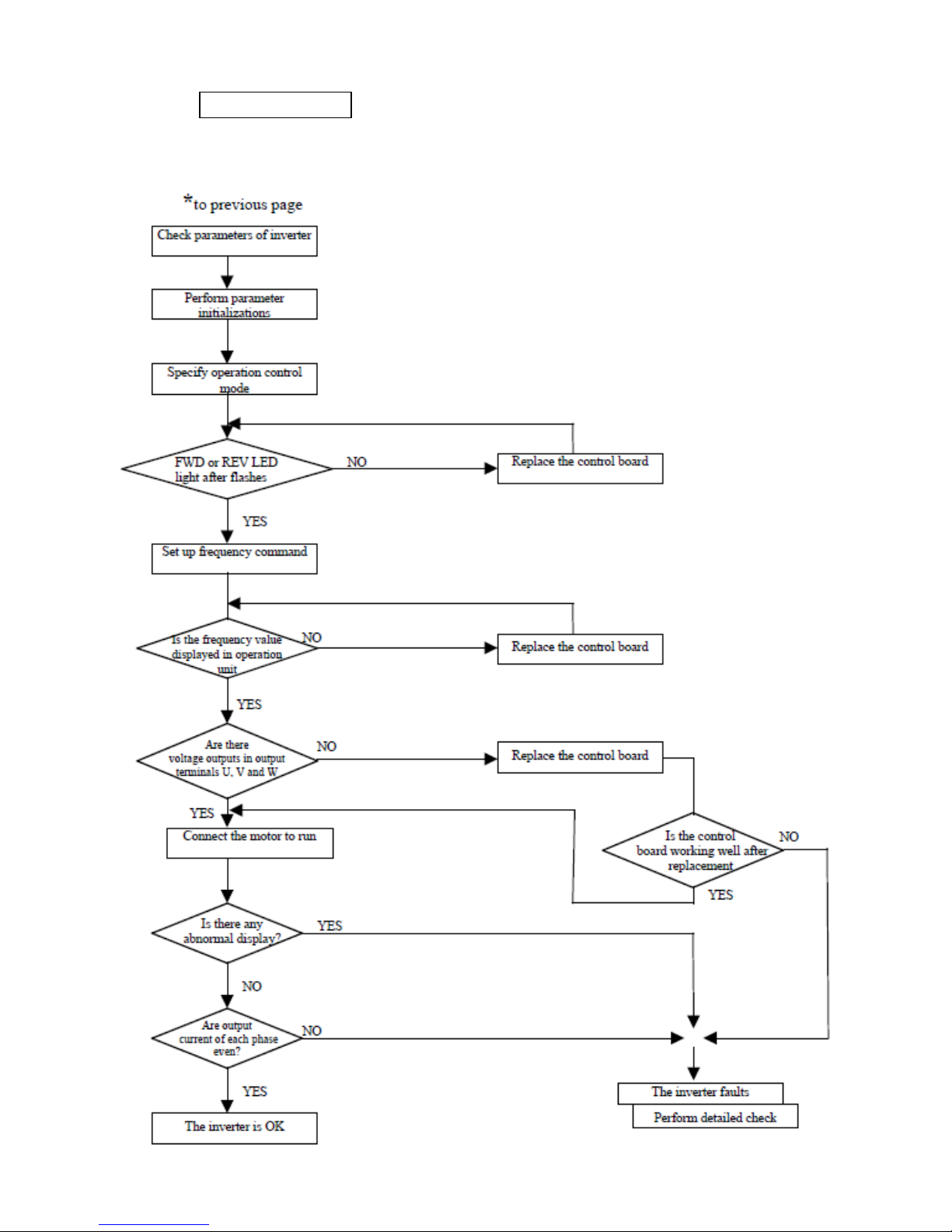
15
Inverter
Fault

1
17
Inverterfault

18
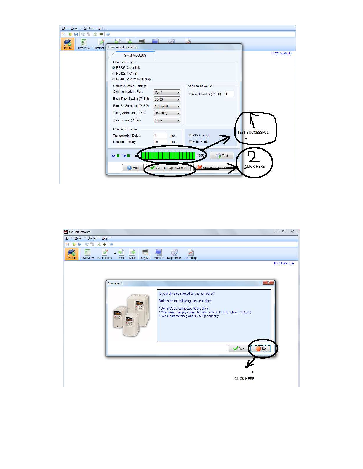
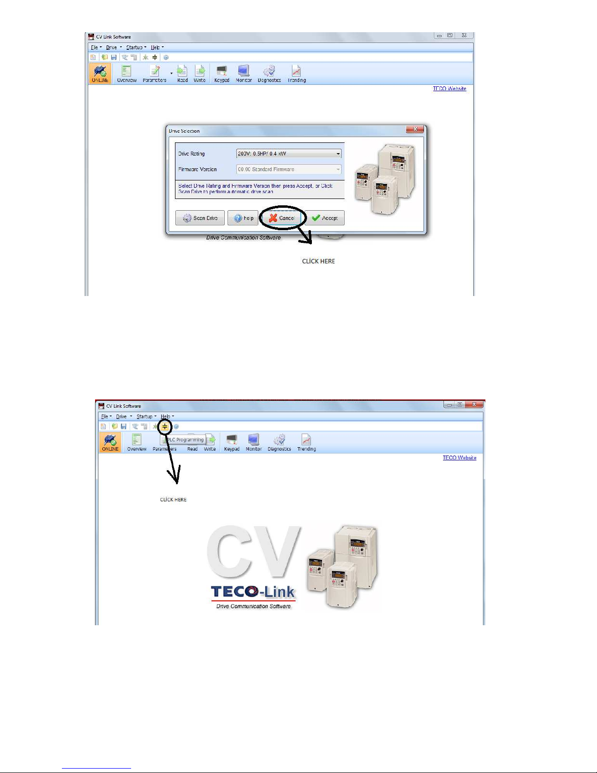
7. INVERTER CONTROL BY A LAPTOP
Inverter settings can be changed by the program named
SYNPLUS
and to connect to inverter over a laptop
RS232 cable is needed. Then follow the instructions to change settings.
19
20
Other manuals for EFE 1500
1
This manual suits for next models
1
Table of contents


