Smacq Technologies Co., Ltd. USB-1000 Series User manual
USB-1000 Series Multi-Function
Data Acquisition Devices
USB-1252/USB-1252A
User Manual
Rev: C
Smacq Technologies Co., Ltd.
www.smacq.com
www.smacq.cn

2
Contents
1. Product Overview ..........................................................................................................................4
1.1. Overview .................................................................................................................................4
1.2. Block Diagram.........................................................................................................................4
1.3. Product Features ......................................................................................................................4
1.4. Product Specifications.............................................................................................................5
Analog Input ...................................................................................................................5
Digital IO ........................................................................................................................6
Counter............................................................................................................................6
Bus Interface ...................................................................................................................6
Power Requirements .......................................................................................................6
Other Specifications........................................................................................................6
2. Description on Appearance and Signal Connection....................................................................8
2.1. Appearance..............................................................................................................................8
2.2. Signal Connection .................................................................................................................10
Connecting Analog Input Signal ...................................................................................10
Connecting Digital IO Signals and Counter..................................................................12
2.3. USB Cable Reinforcement ....................................................................................................14
3. Installation and Testing ...............................................................................................................14
3.1. Driver Installation..................................................................................................................14
3.2. Hardware Installation ............................................................................................................15
4. Analog Input.................................................................................................................................16
4.1. Overview ...............................................................................................................................16
4.2. Input Range Description........................................................................................................17
Single-Ended Mode.......................................................................................................17
Differential Mode..........................................................................................................17
4.3. Description on Multi-Channel Scanning ...............................................................................17
Sampling rate ................................................................................................................17
Input Ranges .................................................................................................................17
4.4. Trigger Sources......................................................................................................................18
4.5. Analog Input Mode................................................................................................................18
4.6. Floating Signal Source...........................................................................................................19
Using Differential Connections for Floating Signal Source..........................................19
Using Non-Referenced Single-Ended (NRSE) Connections for Floating Signal Sources
......................................................................................................................................22
Using Referenced Single-Ended (RSE) Connections for Floating Signal Sources.......23
4.7. Ground-Referenced Signal Source ........................................................................................24
Using Differential Connections for Ground-Referenced Signal Source .......................24
Using Non-Referenced Single-Ended (NRSE) for Ground-Referenced Signal Sources
......................................................................................................................................25
Using Referenced Single-Ended (RSE) for Ground-Referenced Signal Sources..........26
5. Digital IO ......................................................................................................................................26
5.1. Overview ...............................................................................................................................26

3
5.2. Connecting Digital I/O Signal ...............................................................................................26
6. Counter .........................................................................................................................................27
6.1. Overview ...............................................................................................................................27
6.2. Event counter.........................................................................................................................28
6.3. Period/Positive/Negative Pulse Width Measurement ............................................................28
6.4. Connecting Counter Signals..................................................................................................28
7. Programming Instructions..........................................................................................................29
7.1. Overview ...............................................................................................................................29
7.2. Basic functions ......................................................................................................................29
FindUSBDAQ() ............................................................................................................29
OpenDevice()................................................................................................................30
CloseDevice()................................................................................................................30
ResetDevice()................................................................................................................30
7.3. Analog Input Related Functions ............................................................................................30
SetUSB1AiRange().......................................................................................................30
SetSampleRate()............................................................................................................31
SetChanMode().............................................................................................................31
SetChanSel() .................................................................................................................31
SetSoftTrig() .................................................................................................................32
7.4. Digital IO Related Functions.................................................................................................32
SetDioOut()...................................................................................................................32
7.5. Counter Related Functions ....................................................................................................33
SetCounter()..................................................................................................................33
StartCounter()................................................................................................................33
ClearCounter() ..............................................................................................................33
7.6. Read Data Control Functions.................................................................................................34
StartRead() ....................................................................................................................34
StopRead() ....................................................................................................................34
GetAiChans() ................................................................................................................34
GetDioIn().....................................................................................................................35
GetCounter() .................................................................................................................35
GetCtrTime().................................................................................................................35
ClearBufs()....................................................................................................................36
TransDioIn()..................................................................................................................36
7.7. Error Code.............................................................................................................................36
7.8. Instructions for LabVIEW Developecr..................................................................................37
7.9. Instructions for MATLAB Developer....................................................................................37
8. Ordering Information..................................................................................................................38
9. Service and Warranty..................................................................................................................39
10. Revision History...........................................................................................................................40

4
1. Product Overview
1.1. Overview
The new USB-1000 series multi-function data acquisition (DAQ) device provides a new option
for convenience and quick start of data acquisition application. Its exquisite shape provides super
portable and very flexible installation.
USB-1000 series DAQ devices provide 12-bit, up to 500kS/s sampling rate, and up to 16 analog
signal acquisition channels. You can set the range as 0~10V or ± 5V via software.
With 16 digital input/output channels and 4 counter channels, USB-1000 series DAQ device offers
you the flexibility to build automatic control system of any size.
1.2. Block Diagram
1.3. Product Features
12-bit analog input (AI) resolution.
Up to 500kS/s analog input (AI) sampling rate. (Up to 200kS/s with multiple channels
enabled.)
Sampling period configurable by steps of 20ns.
Up to 16 single-ended AI channels or 8 differential AI channels configurable via
software.
Figure 1. Block Diagram of USB-1000 series DAQ device
Digital IO
Counter
USB bus
AI

5
0~10V or ±5V configurable via software.
Onboard 16K sampling point FIFO buffer.
Up to 16 digital input (DI) channels and 16 digital output (DO) channels.
Up to four 32-bit counter channels.
LabVIEW, Visual Studio and MATLAB development support.
1.4. Product Specifications
The following product specifications, unless otherwise stated, are measured at the temperature of
25°C and the humidity of 40%.
Analog Input
Number of AI Channels
16 single-ended channels or 8 differential channels
configurable via software.
Synchronous Sampling
No
AI Resolution
12-bit
Converter Type
SAR
Sampling Rate
Single-channel acquisition: 500kS/s maximum
Multiple-channel acquisition: 200kS/s maximum
Timing Resolution
20ns
AI FIFO Buffer
16k sampling point
Range
0~10V or -5~5V configurable via software.
Safe Voltage
±15V, the DAQ device may be damaged if the input voltage
exceeds this safe voltage.
Input Impedance
>1GΩ (Power On)
Input Coupling Mode
DC
Trigger Mode
Software trigger
System Noise
NRSE 0~10V range: 0.15mVrms
NRSE ±5V range: 0.3mVrms
DIFF 0~10V range: 0.2mVrms
DIFF ±5V range: 0.4mVrms
AbsoluteAccuracy
NRSE 0~10V range: 2.8mV
NRSE ±5V range: 3mV
DIFF 0~10V range: 3mV
DIFF ±5V range: 4mV

6
Digital IO
Number of DO Channels
16
High Level Output Voltage
3.0~3.4V
Low Level Output Voltage
0~0.1V
Number of DI Channels
16
Low Level Input Voltage
3.3~5V
High Level Input Voltage
0~0.5V
Counter
Number Of Counters
4
Resolution
32-bit
Counter Measurement
Edge Count,
Counting Direction
Count Up
Maximum Input Frequency
1MHz
Bus Interface
USB Interface Specification
USB 2.0 High-Speed Interface
USB Interface Connector
USB Series Type-B Connector
Power Requirements
USB Bus Power Supply
4.75~5.25VDC
Current Consumption
About 300mA
Other Specifications
Dimensions (mm)
Without Connector: 156*102*26
With Connector:161*102*26
Weight
About 420g
Analog Channel Signal Connector
10-PIN Screw Terminal Connector
Digital IO and Counter Connector
40-PIN IDC Connector
Operating Environment
0°C ~55°C
5%RH~90%RH, Non-Condensing
Storage Environment
-40°C ~85°C
7
5%RH~90%RH, Non-Condensing

8
2. Description on Appearance and Signal
Connection
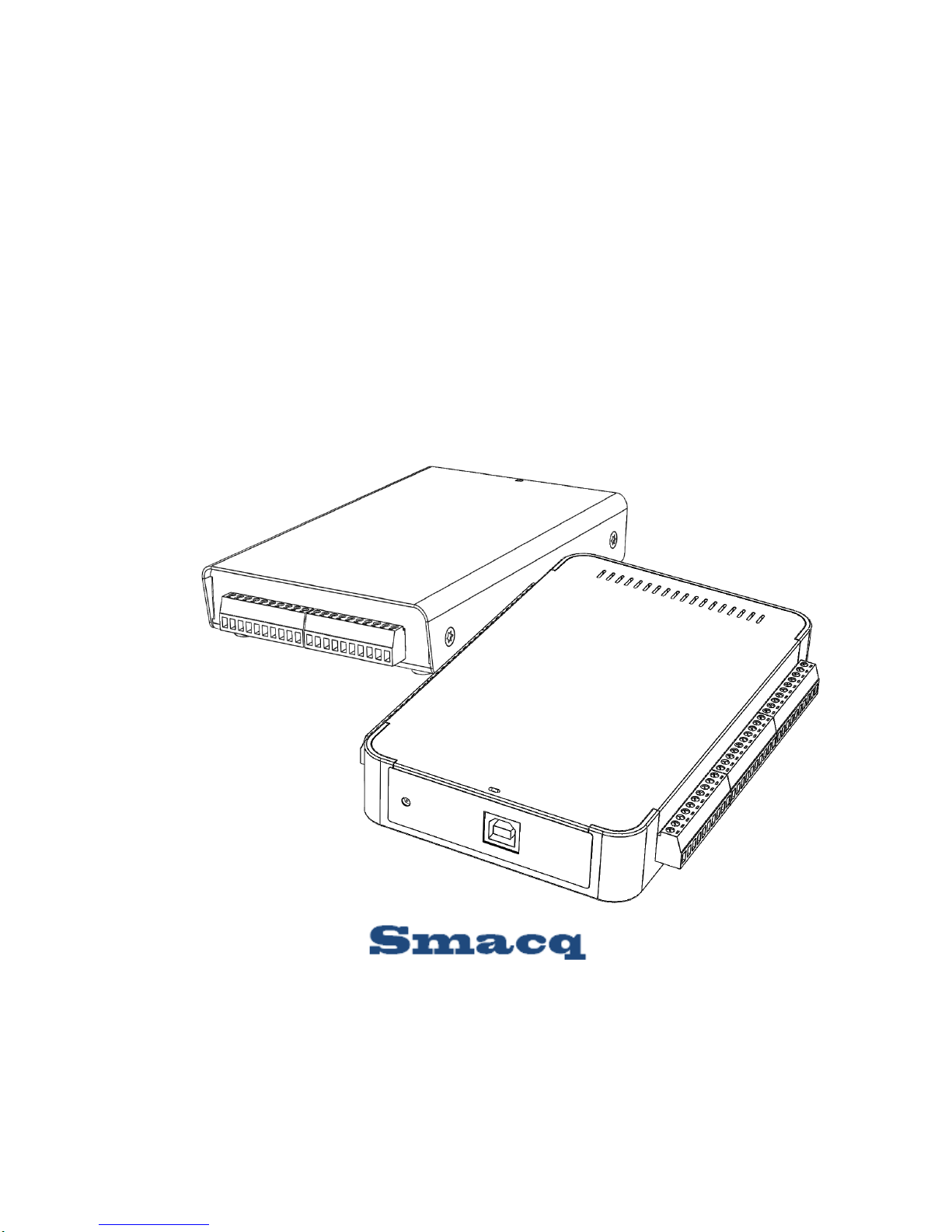
2.1. Appearance
USB-1000 series DAQ device uses metal shielding enclosure, with AI signals connected with
plug-in screw terminal connectors, digital IO signals and counter signals connected with 40-PIN
IDC connectors, and USB communication interface connected with USB series type-B connector.
Figure 2 shows the overall appearance and dimensions (in mm) of the product.
Sensors generate electrical signals to measure physical phenomena, such as temperature, force,
sound, or light. Strain gauges, thermocouples, thermistors, angular encoders, linear encoders, and
resistance temperature detectors (RTDs) are commonly used sensors.

9
Figure 2. External View of USB-1252 DAQ Device

10
2.2. Signal Connection
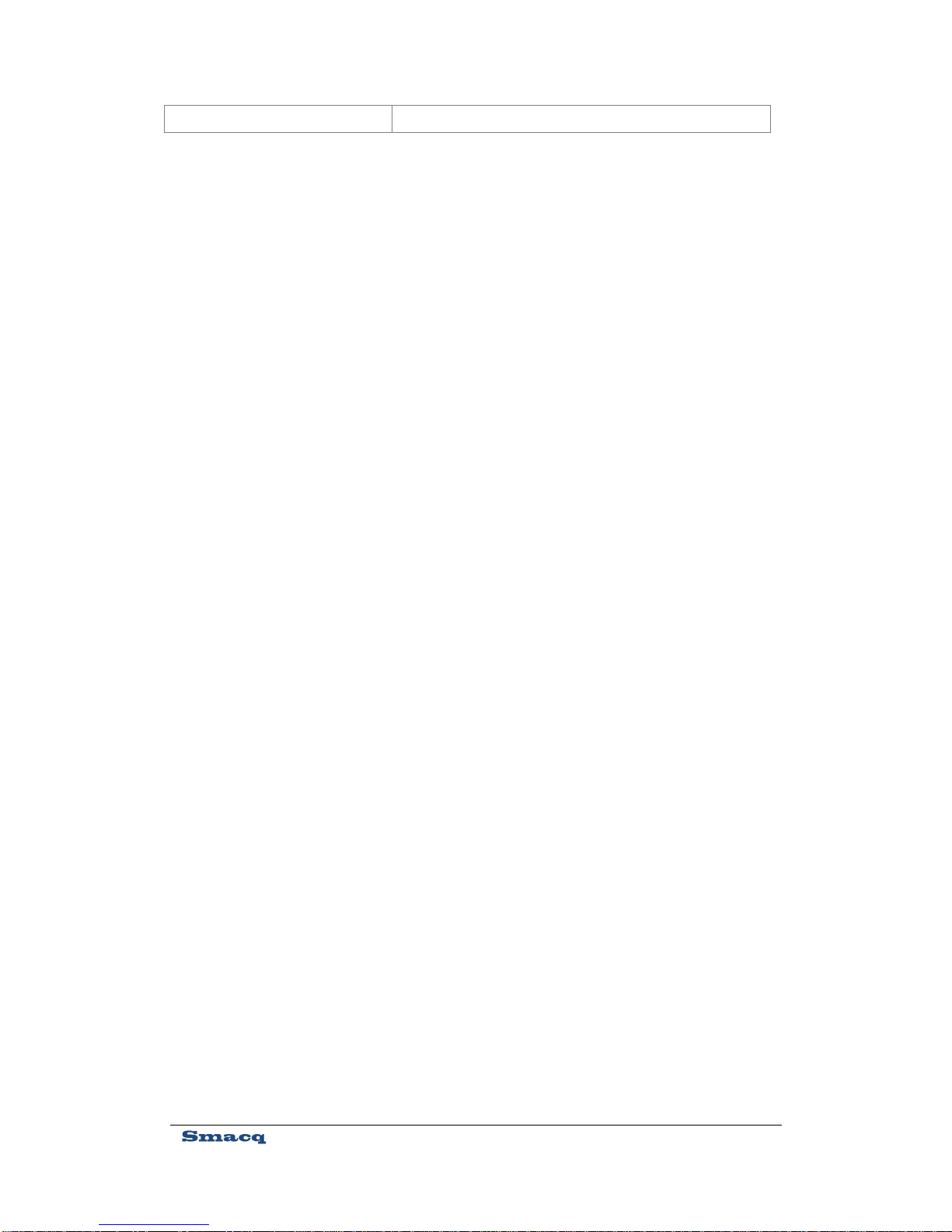
Connecting Analog Input Signal
The screw terminal connector, located in front of the DAQ device, is used for connecting AI
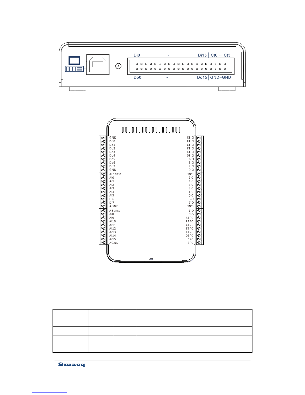
signals. Figure 3 and Table 1 show its pin distribution and corresponding signals. Unused AI
channels should be grounded so as to reduce system noise and achieve higher stability.
Figure 3. External View of USB-1252A DAQ Device
11
Table 1 Mapping of Pins and Signals of Screw Terminal
Name
Description
ai-sense
Reference end input for Non-Referenced Single-Ended (NRSE) signal
ai-gnd
Analog ground
ai-0
AI channel, ai0 for single ended, and ai0+ for differential
Figure 4. Pin Distribution and Corresponding Signals of Screw
Terminal Connector
Figure 5. Pin Distribution and Corresponding Signals of Screw
Terminal Connector

12
ai-1
AI channel, ai1 for single ended, and ai0- for differential
ai-2
AI channel, ai2 for single ended, and ai1+ for differential
ai-3
AI channel, ai3 for single ended, and ai1- for differential
ai-4
AI channel, ai4 for single ended, and ai2+ for differential
ai-5
AI channel, ai5 for single ended, and ai2- for differential
ai-6
AI channel, ai6 for single ended, and ai3+ for differential
ai-7
AI channel, ai7 for single ended, and ai3- for differential
ai-8
AI channel, ai8 for single ended, and ai4+ for differential
ai-9
AI channel, ai9 for single ended, and ai4- for differential
ai-10
AI channel, ai10 for single ended, and ai5+ for differential
ai-11
AI channel, ai11 for single ended, and ai5- for differential
ai-12
AI channel, ai12 for single ended, and ai6+ for differential
ai-13
AI channel, ai13 for single ended, and ai6- for differential
ai-14
AI channel, ai14 for single ended, and ai7+ for differential
ai-15
AI channel, ai15 for single ended, and ai7- for differential
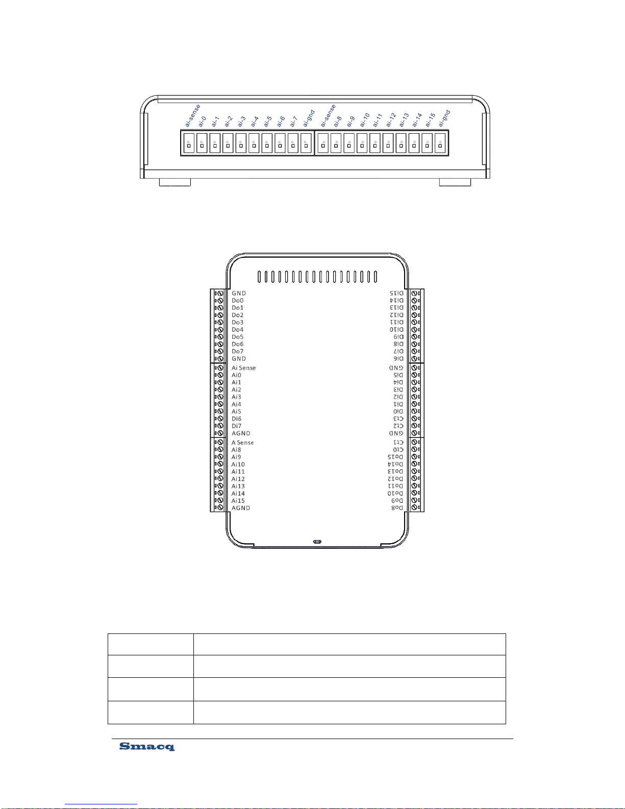
Connecting Digital IO Signals and Counter
The IDC connector, located at the back of the DAQ device, is used for connecting digital IO
signals and counter signals. Figure 4 and Table 2 show its pin distribution and corresponding
signals.
13
Table 2 Mapping of Pins and Signals of Screw Terminal
Name
Reference
Direction
Description
Di0~Di15
GND
Input
DI channels
Do0~Do15
GND
Output
DO channels
Ct0~Ct3
GND
Input
Counter channels
GND
Digital ground
Figure 6. Pin Distribution and Corresponding Signals of IDC
Connector
Figure 7. Pin Distribution and Corresponding Signals of Screw
Terminal Connector

14
2.3. USB Cable Reinforcement
To prevent USB connectors from falling off accidentally, a binding band is provided to be used to
fix the USB cable to the body of the USB-1000 series DAQ devices. Refer to Figure 5 for
installation.
3. Installation and Testing
3.1. Driver Installation
If you intend to use USB-1000 series DAQ device on a PC running Windows, you need to install
the driver to make the OS recognize the DAQ device.
Here we take Windows7 operating system as an example. The driver installation steps are as
follows: (for Windows8, Windows8.1 and Windows10 operating systems, it is required to disable
the driver signature authentication during booting. For Windows XP operating system, it can be
used directly without any other settings.)
1) Open the Device Manager of the Windows operating system.
2) Right click on the device with an exclamation point
, and select Update Driver Software....
3) In the pop-up dialog box, select Browse my computer for driver software.
Figure 8. USB Cable Reinforcement

15
4) Then, choose Select from a list of device drivers on my computer.
5) Keep the default and click Next, and then click Have Disk.
6) In the pop-up dialog box, click Browse, go to the \USB-1000 Series DAQ\dirver folder
in the ResourceCD, find the Win7 folder, and then go to the x86 folder for 32-bit
operating system and x64 folder for 64-bit operating system, and finally select the
gusb.inf file, and click Open. (Windows8, Windows8.1, and Windows10 use the same
driver file as Windows7.)
7) Click OK in the Install from Disk dialog box.
8) Click Next. If a Windows security warning dialog box appears, you need to choose the
second option Always install this driver software.
9) The system starts the installation, which will take about 30 seconds. Upon the driver
installation is completed, you can see that the exclamation point in the Device Manager
disappears, as shown in Figure 6.
3.2. Hardware Installation
For connection of testing signals, refer to detailed description on connections of AI, digital IO and
counter in the subsequent sections.
After installing the driver and correctly connecting signals, you can run any one of the routines of
the USB-1000 series DAQ device in the ResourceCD. The acquired signals will be shown.
Figure 9. Device Manager Display with Driver Correctly Installed

16
4. Analog Input
4.1. Overview
With 16 AI channels, USB-1000 series DAQ device can be configured as 16 single-ended input
channels or 8 differential input channels. Figure7 shows the block diagram of analog input
function of the USB-1000 series DAQ device.
The AI block diagram of the USB-1000 series DAQ device includes the following main
components:
MUX: A multiplexer, routing and inputting the signal from the desired channel to the
instrumentation amplifier.
AI mode setting: Set AI to differential input (DIFF), Referenced Single-Ended (RSE), or
Non-Referenced Single-Ended (NRSE). Refer to Section 4.2 for detailed description on these
modes.
PGIA: Programmable gain instrumentation amplifier, used for setting input ranges.
ADC:An analog to digital converter.
AIFIFO:Data buffer FIFO.
Figure 10. Block Diagram Of Analog Input
Input Range
setting
AI mode
setting

17
4.2. Input Range Description
Single-Ended Mode
For single-ended input mode, positive input is connected to ai-n, and negative input to ai-gnd or
ai-sense. Its input range can be set to 0~10V or ±5V via the software.
Differential Mode
For DIFF Mode, positive input is connected to AI+, and negative input to AI-. Its input range can
be set to 0~10V or ±5V via the software.
The voltage from AI+ and AI- can vary in the range of -10V~10V. The actually measured voltage
value is the difference of voltage between AI+ pin andAI- pin.
When the input range is set to 0~10V, voltage range that can be measured in differential mode
shall meet the following conditions:
The voltages from both AI+ and AI- are in the range of -10V~10V, and the voltage in the range of
0V ≥ (AI+) – (AI-) ≤ 10V can be measured correctly.
When the range is set to -5V~5V, voltage range that can be measured in differential mode shall
meet the following conditions:
The voltages from both AI+ and AI- are in the range of -10V~10V, and the voltage in the range of
-5V ≥ (AI+) – (AI-) ≤ 5V can be measured correctly.
4.3. Description on Multi-Channel Scanning
Sampling rate
In multi-channel scanning applications, the PGIA will need enough settling time in switching
channels. In such case, the sampling rate can be set to 200kS/s at maximum.
Setting sampling rate higher than actually required sampling rate should be avoided, as lower
sampling rate makes the PGIA having more sufficient settling time, so that the accuracy of data
acquisition can be improved.
Input Ranges
The input range of the DAQ device should be set uniformly. In multi-channel scanning
applications, all the channels shall have a same range.

18
4.4. Trigger Sources
When USB-1000 series DAQ acquires signals via analog input, its trigger source can be set to
trigger by software or trigger by the rising edge or falling edge of digital IO input channel DIN0
port.
4.5. Analog Input Mode
The AI channel of USB-1000 series DAQ device can be configured as Referenced Single-Ended
(RSE), Non-Referenced Single-Ended (NRSE) or Differential Input (DIFF) mode. Table 3 shows
the recommended analog input modes for floating signal source and ground-referenced signal
source.
Table 3 Analog Input Mode
Analog Input
Mode
Floating Signal Sources (Not
connected to the building ground)
Ground-Referenced Signal source
Example
Ungrounded thermocouple
Isolated output signal
Battery-powered devices
Non-isolated output signal
Differential
Input
(DIFF)
Non-Referenced
Single-Ended
(NRSE)
Signal source
Signal source
Signal source
Signal source

19
Referenced
Single-Ended
(RSE)
4.6. Floating Signal Source
A floating signal source is not connected in any way to the building ground system, and instead it
has an isolated ground-reference point. Some examples of floating signal sources are outputs of
transformers, thermocouples, battery-powered devices, optical isolators, and isolation amplifiers.
An instrument or device that has an isolated output is a floating signal source.
Using Differential Connections for Floating Signal Source
Use DIFF mode for connections of floating signal sources when any of the following conditions
are met:
Two analog input channels, AI+ andAI-, are available for the signal.
The input signal is low level and a high accuracy is required.
The leads connecting the signal to the DAQ device are greater than 3m.
The input signal requires a separate ground-reference point or return signal.
The signal leads travel through noisy environments.
DIFF signal connections reduce noise pickup and increase common-mode noise rejection.
For floating signal source with impedance less than 100Ω, it is allowable to connect the negative
side of the signal to AI- and AI-GND, and connect the positive side of the signal to AI+, as shown
in Figure 8 below.
Signal source
Ground-loop
potential (VA –
VB) are added
to measured signal.
Signal source
When measuring a floating signal, make sure the negative input is
directly connected to the AGND, or indirectly through a resistor
connected to theAGND.

20
However, for floating signal source with larger impedance, this connection leaves the DIFF signal
off balance. Common-mode noise will couple onto AI+ signal instead of AI- signal. Such,
common-mode noise will appear in your measured data. In this case, connect AI- port and
AI-GND port through a bias resistor that is about 100 times the equivalent source impedance, as
shown in Figure 9. In such way, the resistor puts the differential signal nearly in balance, so that
about the same amount of noise couples onto both ends of the signal, yielding better rejection of
common mode noise.
However, for floating signal source with larger impedance, you can also use DIFF Mode using
two bias resistors, as shown in Figure 10. This fully balanced bias resistor connection offers
Figure 11 Differential Connection for Floating Signal Sources without Bias Resistor
Figure 12. Differential Connections for Floating Signal Source with Single Bias Resistor
This manual suits for next models
2
Table of contents
Popular Computer Hardware manuals by other brands


ATTO Technology
ATTO Technology FastStream SC 8500E Specification sheet

Freescale Semiconductor
Freescale Semiconductor MTRCKTSPS5604P quick start guide

Aaeon
Aaeon NEZHA-N97 user manual

D-Link
D-Link DUB-1320 Technical specifications

sparkfun
sparkfun DEV-14034 HOOK-UP GUIDE

Sony Ericsson
Sony Ericsson GC79 user guide

Crystal Vision
Crystal Vision TANDEM 3G user manual

Panasonic
Panasonic SH-AC300 operating instructions

Delta Electronics
Delta Electronics SMT Couple Inductor DHCB Product specifications

Lumistar
Lumistar LS-3x Series user manual

ekwb
ekwb EK-FC590 GTX Installation and mounting manuals

Benezan Electronics
Benezan Electronics NetBob2 installation manual