Smallart RP-2027 Series User manual
RP-2027
ROOM CONTROL PANEL
Doc: 00-12-01, V1.3, 20170201 Page 1 / 4
Copyright © Smallart®
www.smallart.com.tr
1RP-2027 Series Room Sensor User Manuel
1.1 Features
1.2 Applications
2Technical Specification
Power Supply
Operation Voltage
12VDC
Power Consumption
< 1W
Wirings
Screw-in terminals, each terminal
capable of accepting 2 × 1.5 mm2
or 1 × 2.5 mm2wires
Temperature Input
Type
NTC
Display Range
0~50°C
Accuracy
± 1°C
Communication
Communication Type
RS485, Peer to Peer
Protocol
Modbus RTU
Cabling
Shielded Twisted Pair (STP),
RS485 Data Communication Cable
2 X 2 X 0,34…0,75mm2
Operation
Temperature
0~45°C
Humidity
5~90%RH (non-condensing)
General
Setpoint Range
5℃~35°C
Dimensions
86 × 86 × 22.2 mm (W × H × D)
Hole Pitch
60 mm (Standard)
Protection Class
IP30
3Display and Operations
3.1 Overview
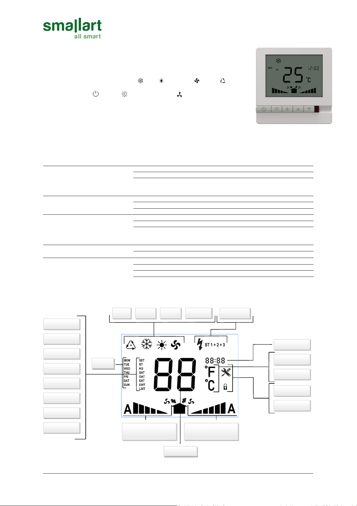
RP-2027 adopts digital control technology with large LCD display. It shows the
following items: working status (Cool , Heat , Ventilation or Auto ), the
speed of two fans, room temperature, set-point etc. There are following keys on
the panel: On/Off “ ”, Mode “ ”, Select fan speed “ ”, set-point temperature
“” and “”.
This product can be used all USC-HRV Series HVAC controllers, USC-FCU Series
Fan Coil Unit controllers, USC-HP Series Heat Pump controllers, USC-VAV Series
Variable Air Volume controllers, USC-TH Series Trench Heater controllers.
Heating
Ventilation
Days
Room Tmp
Setpoint
Tmp Value
Supply Air Fan Speed
Auto-5-4-3-2-1
Exhaust Air Fan Speed
1-2-3-4-5-Auto
Air Quality
Supp. Air Tmp
Out. Air Tmp
Cooling
Exh. Air Tmp
Ent. Wat. Tmp
Leav. Wat. Tmp
Auto
Heaters
Fahrenheit
Clock
Celcius
Alarm
Keylock
RP-2027
ROOM CONTROL PANEL
Doc: 00-12-01, V1.3, 20170201 Page 2 / 4
Copyright © Smallart®
www.smallart.com.tr
3.2 Keys
-On/Off: Press “ ” to turn on, press “ ” again to turn off.
-Setting temperature: Press “” to reduce set-point, press “” to raise set-point, and 1℃changed
once.
-Mode Selection: Press “ ” to change system working in cooling “ ”, heating “ ”, ventilation “ ” or
auto “ ” mode.
-Fan Speed Selection (Single fan): Press “ ” to change fan speed among Off/Low/Lo-Med/Med/Hi-
Med/High/Auto
-Fan Speed Selection (Double fan): Press “ ” and Supply fan symbol will flash. Press “” or “” to
change fan speed among Off/Low/Lo-Med/Med/Hi-Med/High/Auto. Press “ ” again and Extract fan
symbol will flash. Press “” or “” to change fan speed among Off/Low/Lo-Med/Med/Hi-
Med/High/Auto. Press “ ” or wait for 5 seconds to quit.
3.3 Settings
3.3.1 Key Locking Function Setting
-Turn on the thermostat, Press “ ” and “” for 10 seconds to enable or disable key locking function.
3.3.2 Room Temperature Calibration
-Turn on the thermostat, press “ ” and “ ” for 10 seconds, LCD will display current temperature and
calibration temperature.
-Press “” to reduce calibration temperature or press “” to increase.
3.3.3 Fan/Auto Fan Selection
-Press “ ” for 10 seconds to enable fan or auto fan mode. display “Auto”or “Cont”in the clock area for
5seconds only after a value change. After 5 seconds clock area will return to normal value.
4Extended User Operations
4.1 Clock setup
-When power on, press the button “ ” 10s till to display “hh:mm” and “hh”flash, press “▲”or “▼” to
adjust hour.
-Press “ ”, “mm” flash, press “▲” or “▼” to adjust minute.
4.2 Time Schedules
-After clock setting, press “ ”, “week” flash, press “▲” or “▼” to adjust Mon to Sun.
-Timer ON/Timer OFF: Press “ ” till to display “MON”and “ON”, and also “hh” flash, press “▲”or “▼”
to adjust hour, press “ ”, “mm” flash, press “▲”or “▼” to adjust minute; Press “ ” till to display
“MON”and “OFF”, and also “hh” flash, press “▲”or “▼” to adjust hour, press “ ”, “mm” flash, press
“▲”or “▼” to adjust minute. The setting method is same for other days.
5Configuration Parameters
5.1 Servis Menu Operations
5.1.1 Address Setting
-When power off, press the button “ ” and “” 5s till to display “XX”, “hh:mm”could display the
value. Press “” to raise the parameter’s value, press “” to reduce the parameter’s value.
5.1.2 Technician Parameters
-The parameters which are shown as “Technician Parameters” in the table are application-specific
parameters.
Number
Parameters
Default Value
Range
00
Master PLC ID
00
0…247
01
RP-2027 address (ID)
01
1…32
02
Technician parameter 1
00
-999 … 9999
03
Technician parameter 2
00
-999 … 9999
.
.
.
.
.
.
.
.
99
Technician parameter 98
00
-999 … 9999

RP-2027
ROOM CONTROL PANEL
Doc: 00-12-01, V1.3, 20170201 Page 3 / 4
Copyright © Smallart®
www.smallart.com.tr
6General Description
6.1 Error Messages
The error messages for the device are given below;
When the thermostat fails to communicate with the
controller, this error occurs.
When the sensor on the termostat is damaged, this
error occurs.
6.2 Safety Advise
Caution: This device is intended to be used for comfort applications. Where a device failure endangers human
life and/or property, it is the responsibility of the owner, designer and installer to add additional safety devices
to prevent or detect a system failure caused by such a device failure. Ges Teknik or its affiliates cannot be held
liable for any damage caused by such a failure. Failure to follow specifications and local regulations may
endanger life, cause equipment damage and void warranty.
6.3 Mounting Location
Install the room thermostat on an easy accessible interior wall, approx. 1.5 m above the floor in an area of
average temperature.
Keep away from sunlight or other heat sources.
If external temperature sensors are used, room thermostat’s location of mounting is less critical.
6.4 Insatallation
Use the flush mounting box for each application.
6.4.1 Single Device
- Open the mounting hole to its proper place using
a 68 mm holesaw.
6.4.2 Multiple Device
- Specify the centers of holes to be drilled in the
wall. Distance of between the centers of holes
should be min. 96 mm.
- Open the mounting hole to wall using a 68 mm
holesaw.
RP-2027
ROOM CONTROL PANEL
Doc: 00-12-01, V1.3, 20170201 Page 4 / 4
Copyright © Smallart®
www.smallart.com.tr
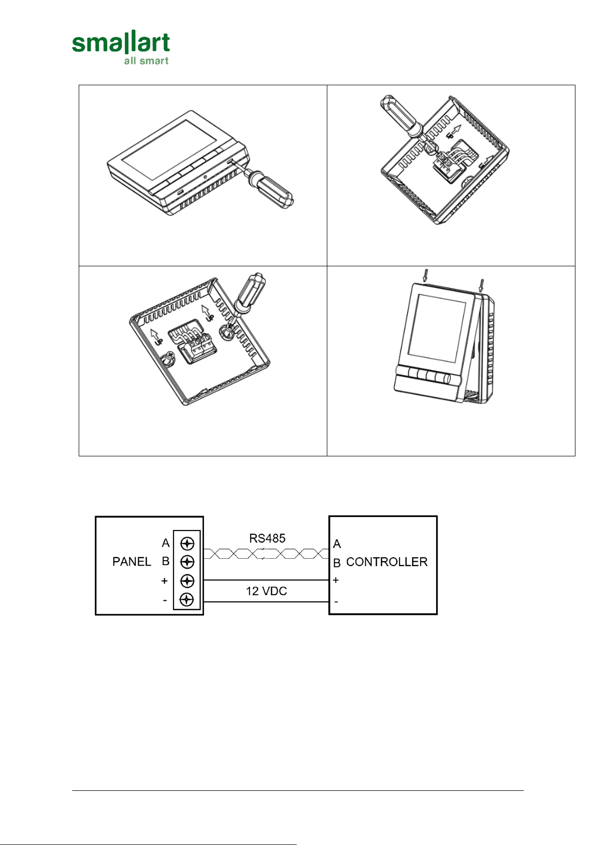
6.4.3 Steps
Note: Be sure to connect all the wires as per the wiring diagrams and keep it away from water, mud
and other material so as to prevent the unit being spoiled!
6.4.4 Wire and Connecting
Shielded, twisted pair, RS485 Data Communication Cable must be used. (2 X 2 X 0,34…0,75mm2)
1. Open the main control panel: put the screwdriver (3.5mm) into
the block 4mm along the bevel. Prize up, open the clips.
2. As per wiring diagram, connect it with terminals, fixed by the
screwdriver.
3. Put the back panel of thermostat to mounting box, then fix it
with the two screws in the packing box.
4. Put the cover with 30 degree angle, then fix the up two clips.
Push the places of the two down clips, fix the cover, and finish the
installation.


