SMAR HI302 User manual

AGO / 02
FOUNDATION
HI 32FME

smar Specifications and information are subject to change without notice.
BRAZIL
Smar Equipamentos Ind. Ltda.
Rua Dr. Antonio Furlan Jr., 1028
Sertãozinho - SP 14170-480
Tel.: +55 16 645-6455
Fax: +55 16 645-6450
e-mail: [email protected]
ARGENTINA
Smar Argentina
Soldado de La Independencia, 1259
(1429) Capital Federal – Argentina
Telefax: 00 (5411) 4776-1300 / 3131
e-mail: smarinfo@smarperifericos.com
CHINA
Smar China Corp.
3 Baishiqiao Road, Suite 30233
Beijing 100873, P.R.C.
Tel.: +86 10 6849-8643
Fax: +86-10-6894-0898
e-mail: info@smar.com.cn
FRANCE
Smar France S. A. R. L.
42, rue du Pavé des Gardes
F-92370 Chaville
Tel.: +33 1 41 15-0220
Fax: +33 1 41 15-0219
e-mail: sm[email protected]r
GERMANY
Smar GmbH
Rheingaustrasse 9
55545 Bad Kreuznach
Germany
Tel: + 49 671-794680
Fax: + 49 671-7946829
e-mail: [email protected]
MEXICO
Smar México
Cerro de las Campanas #3 desp 119
Col. San Andrés Atenco
Tlalnepantla Edo. Del Méx - C.P. 54040
Tel.: +53 78 46 00 al 02
Fax: +53 78 46 03
e-mail: vent[email protected]
SINGAPORE
Smar Singapore Pte. Ltd.
315 Outram Road
#06-07, Tan Boon Liat Building
Singapore 169074
Tel.: +65 6324-0182
Fax: +65 6324-0183
e-mail: info@smar.com.sg
MIDDLE EAST
Smar Middle East
Al Sadaka Tower, Suite 204
P.O. Box 268
Abu Dhabi
Tel: 9712-6763163 / 6760500
Fax: 9712-6762923
e-mail: sm[email protected].ae
USA
Smar International Corporation
6001 Stonington Street, Suite 100
Houston, TX 77040
Tel.: +1 713 849-2021
Fax: +1 713 849-2022
e-mail: [email protected]om
Smar Laboratories Corporation
10960 Millridge North, Suite 107
Houston, TX 77070
Tel.: +1 281 807-1501
Fax: +1 281 807-1506
e-mail: sm[email protected]
Smar Research Corporation
4250 Veterans Memorial Hwy.
Suite 156
Holbrook , NY 11741
Tel: +1-631-737-3111
Fax: +1-631-737-3892
e-mail: sales@smarresearch.com

Introduction
III
Introduction
The HI302 is a hardware component integral to System 302 which main function is to interface
HART devices to Foundation Fieldbus Systems, allowing the user to perform maintenance,
calibration, sensor status monitoring, device status, among others information.
See below some HI302 features:
•Integral Part of System 302;
•Tight integration with different system manufactures due to the use of standard protocols such
as Foundation Fieldbus;
•8 HART master channels;
•Optional Analog Conversion (4-20 mA / Foundation Fieldbus – HI302-I and Foundation Fieldbus
/ 4-20 mA – HI302-O);
•Totally integrated to Asset View;
•Easy to operate due to a uniform system and tools;
•Not-multiplexed and independent HART channels;
•HART Configuration Commands located into the module and possibility to send HART
messages through parameters and bypass;
•Suitable for Asset Management System;
•Complete configuration of Smar devices embedded in HI302 module, thus no additional
configuration is required.

HI302 - User’s Manual
IV

Index
V
Index
INTRODUCTION..............................................................................................................................III
CHAPTER 1 - GENERAL VISION...................................................................................................1.1
General Characteristics..........................................................................................................1.1
Function Blocks......................................................................................................................1.2
Hart Transducer Blocks .........................................................................................................1.2
CHAPTER 2 – INSTALLATION.......................................................................................................2.1
Installation of the HI302 modules...........................................................................................2.1
Mechanical Installation...........................................................................................................2.1
Electrical Connection .............................................................................................................2.2
HART Device Installation.......................................................................................................2.4
Device Physical Types...........................................................................................................2.4
HART Installation Topology...................................................................................................2.5
Supply Voltage x Total Loop Impedance...............................................................................2.5
HI302-N..................................................................................................................................2.6
HI302-I....................................................................................................................................2.7
HI302-O..................................................................................................................................2.7
Maximum Cable Length.........................................................................................................2.8
Other devices in the Loop......................................................................................................2.8
Switching On the HI302 .........................................................................................................2.8
Updating the HI302 Firmware................................................................................................2.9
CHAPTER 3 - BASIC CONFIGURATION.......................................................................................3.1
Instruction on HI302 Configuration ........................................................................................3.1
Configuring the HCFG Block..................................................................................................3.1
HART Communication Operation Parameters.......................................................................3.2
HART Communication Diagnostic Parameters......................................................................3.4
Configuring the HIRT Block ...................................................................................................3.5
Configuring the HVT Block.....................................................................................................3.7
HI302-I – Configuring the MAI Block......................................................................................3.7
HI302-O – Configuring the MAO Block..................................................................................3.8
Starting the HI302 Operation.................................................................................................3.8
CHAPTER 4 – ADVANCED CONFIGURATION.............................................................................4.1
HART Command Definition with HCD and HWPC Blocks ....................................................4.1
Configuration for Specific HART Commands ........................................................................4.1
Commands.............................................................................................................................4.2
Configuring the HCD Block....................................................................................................4.4
HVT Allocation Map ...............................................................................................................4.4
Setting the Definition of the HART Commands in the HCD Block.........................................4.4
Request Parameters..............................................................................................................4.5
Response Parameters ...........................................................................................................4.5
Writing Parameters ................................................................................................................4.5
Setting the HWPC Block Configuration................................................................................. 4.6

HI302 - User’s Manual
VI
CHAPTER 5 - OPERATION ............................................................................................................5.1
Initialization ............................................................................................................................5.1
Leds Status ............................................................................................................................5.1
Understanding the HART Communication.............................................................................5.2
BLK_EXEC_STATE Parameter.............................................................................................5.2
BLK_ERROR and DEVICE_STATUS Parameters................................................................5.3
HIRT Block Operation............................................................................................................5.4
HART Variable Writing and Reading .....................................................................................5.5
Operating the HVT Block .......................................................................................................5.7
Sequence for HVT Reading Cycle.........................................................................................5.8
Writing Sequence in HVT Block Parameter...........................................................................5.8
HI302 versus Portable Programmers (Field Alterations)......................................................5.9
Behavior of the Static Revision (ST_REV) parameter..........................................................5.9
HART Response Code Conversion to Status FF ...............................................................5.10
Bypass Mode ......................................................................................................................5.10
Sequence for Sending a HART message through a Bypass.............................................. 5.11
CHAPTER 6 – BASIC FUNCTIONING THEORY............................................................................6.1
The HI302 Block Diagram......................................................................................................6.1
Hardware................................................................................................................................6.2
Power Supply, Operation Voltage and Protection .................................................................6.2
Hot Swap................................................................................................................................6.2
Regulators..............................................................................................................................6.2
Protection...............................................................................................................................6.3
Processing Core.....................................................................................................................6.3
HI302 Module Resetting.........................................................................................................6.4
H1 Fieldbus Communication..................................................................................................6.5
HART Communication ...........................................................................................................6.5
4-20 mA to Foundation Fieldbus Analog Conversion (HI302-I).............................................6.5
Foundation Fieldbus to 4-20 mA Analog Conversion (HI302-O)...........................................6.6
CHAPTER 7 – AN EXAMPLE OF HI302 USAGE...........................................................................7.1
Installation..............................................................................................................................7.1
Step by Step Configuration....................................................................................................7.1
Step by Step Operation..........................................................................................................7.3
CHAPTER 8 – TROUBLESHOOTING ............................................................................................8.1
Installation..............................................................................................................................8.1
Configuration..........................................................................................................................8.1
Operation ...............................................................................................................................8.1
APPENDIX A....................................................................................................................................A.1
APPENDIX B...................................................................................................................................B.1
APPENDIX C...................................................................................................................................C.1

Chapter 1
1.1
General Vision
This user manual contains instructions on how to configure and install the HI302.
General Characteristics
Among the main characteristics, the following may be mentioned:
•The HI302 supports up to eight peer-to-peer HART devices or 32 HART devices in the
multidrop mode (4 devices per channel);
•8 HART Master communication ports that can be configured as Primary or Secondary;
•1 Foundation Fieldbus H1 Channel;
•Feeding via backplane (5Vdc @500 mA);
•Device Feeding via outside source;
•Input circuits 4-20 mA on HI302 – I (current conversion to Fieldbus);
•Output circuits 4-20 mA on HI302 – O (Fieldbus conversion to current);
There are three models for the HI302, according to the analog conversion needs:
•HI302 – N: only HART communication;
•HI302 – I : HART communication and conversion of eight 4-2- mA analog inputs to FF;
•HI302 – O: HART communication and FF conversion to eight 4-20 mA analog outputs;
General Vision
1.2
Function Blocks
Several blocks were implemented to give the module the required functionality.
HART Transducer Blocks
HCFG (HART Configuration) – Concentrates general configuration parameters for
module working, in addition to parameters on HART Communication performance and
diagnostic.
HIRT (HART Identification and Real Time data) – This block contains the main
parameters, i.e., the most commonly used, besides dynamic variables. All parameters
related to universal commands and some main “Common Practice” commands are found
here. There should be one HIRT block for each HART device installed, up to 32 blocks. In
normal operation, the HIRT block parameters show the HART device variables, since
there are mechanisms to keep the HI302 database updated. See the Appendix A or the
Function Blocks handbook for details.
HVT (HART Variable Template) – This block is a large collection of variables for general
use arranged in arrays. It is now possible to access any HART instrument parameter. To
this effect, the module should get a configuration (HCD and HWPC blocks) to define the
specific instrument one wants to access, and how these commands will relate to each
parameter on the block. There is just one HVT block that should be shared among the
devices when accessing them through the HART_TAG. This configuration is already
configured in the Smar device’s memory.
Process View
(Workstation)
S
yscon
(Configuration Station) Asset View
(Maintenance)
Up to 15 devices per channel in multidrop mode.
(Only digital communication with fixed current)
Secondary Master
Multidrop Mode
Point to Point Device
(HART + 4-20 mA)
Primary Master
Up to 32 Devices
Power Supply

HI302 - User’s Manual
1.3
HCD (HART Command Definition) – It contains the HART command description for each
device type or version. This description stores information needed by the module to
communicate and the data read on the HIRT or HTV blocks. The HCD blocks defining the
universal and the common practice commands, as well as all commands specific to Smar
instruments, are already stored in the equipment’s memory and do not require any
configuration from the user. See the Appendix B for details.
HWPC (HART Writeable Parameter Command Correlation) – This block stores
information about all parameters to be written on the instrument and mapped on the HVT
block.
See table with detailed definitions on the Appendix A blocks.
In order to support the analog circuits on HI302-I and HI302-O modules, use the MAI or
MAO blocks, respectively, to convert the analog 4-20 mA standard to FF or FF to 4-20
mA. Inquire about our availability of AI or AO blocks.
MAI – Multiple Analog Input
The MAI block makes available to the fieldbus network 8 variables of the I/O subsystem
through 8 output parameters, namely, OUT_1 to OUT_8. These parameters correspond to
the current value, in percentage, on the 8 analog inputs.
MAO – Multiple Analog Output
The MAO block makes available to the I/O Subsystem 8 input parameters, IN_1 to IN_8.
These parameters correspond to the current value on the 8 analog outputs.

General Vision
1.4
Chapter 2
2.1
Installation
This chapter deals with the main physical installation features, namely: mechanical and
electrical elements.
IMPORTANT
All comments or considerations made in this manual refer to HART communication using
FSK modulation (Frequency Shift Keying).
Installation of the HI302 modules
Mechanical Installation
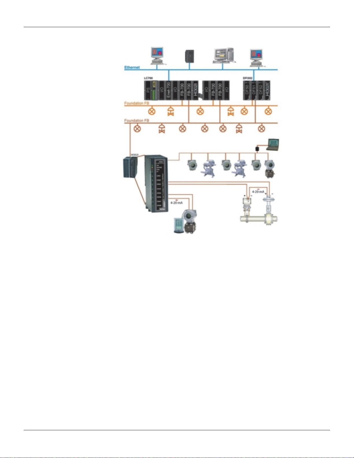
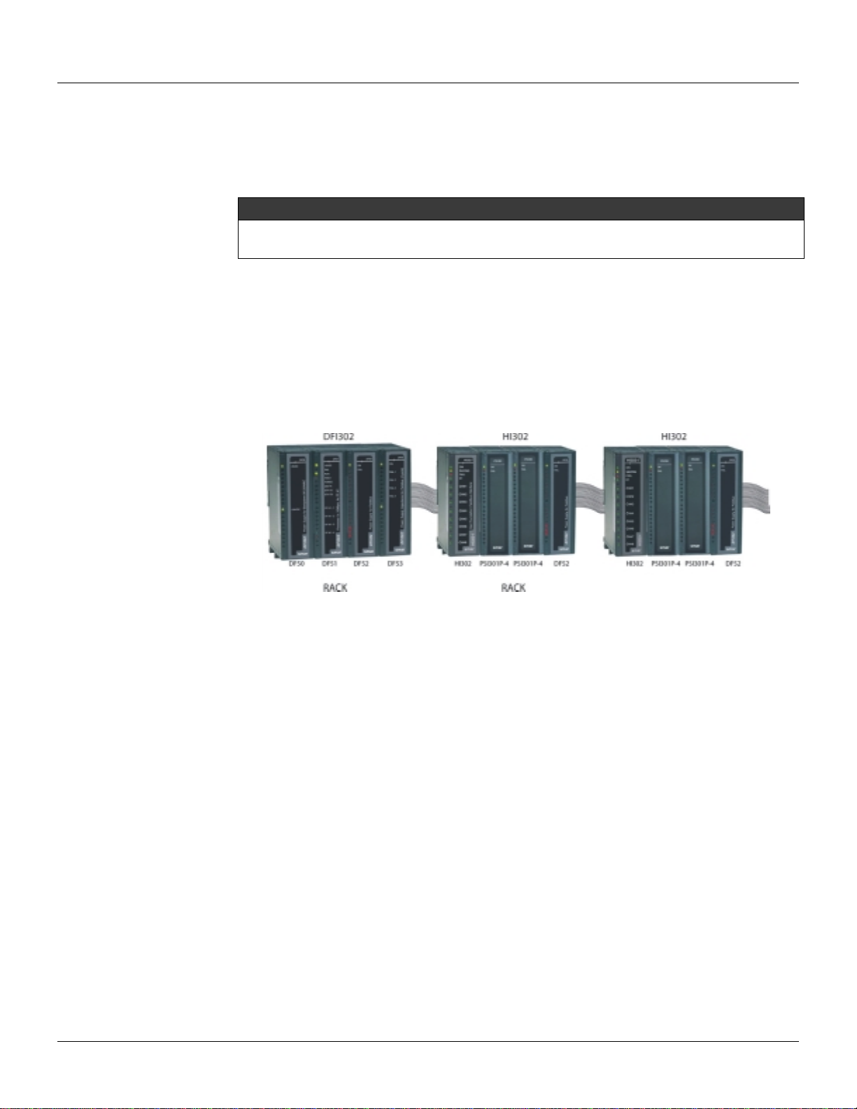
The HI302 modules are enclosed in the Smar standard plastic housing, like the LC700
and the DFI302. Therefore, they are fully interchangeable on the standard racks. The
picture below shows a typical HI302 installation set:
The HI302 requires just one 5V @ 500 mA power supply. We recommend the Smar PS-
AC or DF50 power supply modules. Besides providing a high quality feeding, they also
provide a “Power Fail” signal to prevent power failure or AC problems. However, the user
can use another power supply, provided it meets the minimum requirement of quality and
safety.
The other elements follow the same installation procedure as Foundation Fieldbus and
HART devices. For more information on installation procedures, visit our www.smar.com
site and download a Smar handbook copy free of charge.
BASIC SE
T
Installation
2.2
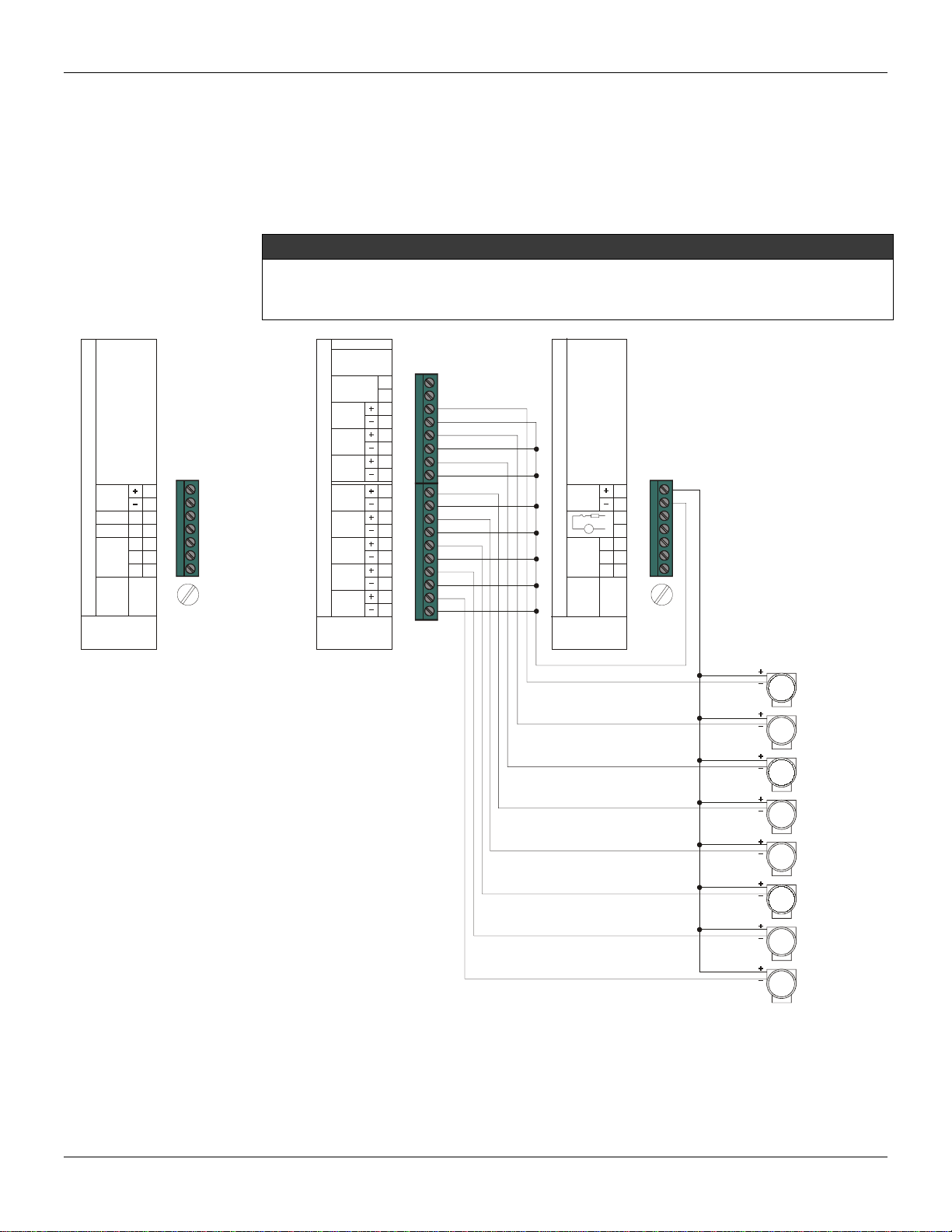
Electrical Connection
The minimum electrical connections for the HI302 relate to the power supply, normally
connected to the rack, to the connection with the H1 communication bus and to the
connection with HART devices. See the following picture for details. Since the HI302 does
not feed the devices, it is necessary to use a power supply for them.
IMPORTANT
Since the HI302 H1 channel is a passive channel, it is not necessary to use the bus
power supply. For instance, if the DF51 channel is connected to the HI302 channel, they
will communicate normally. However, impedance should be used.
The picture above shows the connection of devices fed by the same power supply
module. Remember that the HI302-I and HI302-O analog inputs and outputs are isolated.
smar
1B
2B
3B
4B
5B
6B
7B
FUSE
2A
L
G
IN
90-264VAC
OUT
24VDC
DF50-PowerSupplyforBackplane90-264VAC
N
smar
HI302-I(8HARTMaster+4-20mAInputs/FieldbusH1)
1B
2B
3B
4B
5B
6B
7B
8B
9B
10B
3A
FF H1
CH#4
CH#5
CH#6
CH#7
CH#8
CH#1
CH#2
CH#3
5A
4A
6A
7A
8A
9A
10A
Reset / Fct Init
smar
1B
2B
3B
4B
5B
6B
7B
FUSE
2.5A
L
G
IN
90-264VAC
127-367VDC
OUT
24VDC
DF52-PowerSupplyforFieldbus90-264VAC/127-367VDC
N
Fail
V
TT301/FY301
Rack
Power Supply
(5VDC)
HI302-I
or
HI302-O
TT301/FY301
TT301/FY301
TT301/FY301
TT301/FY301
TT301/FY301
TT301/FY301
TT301/FY301
HI302 - User’s Manual
2.3
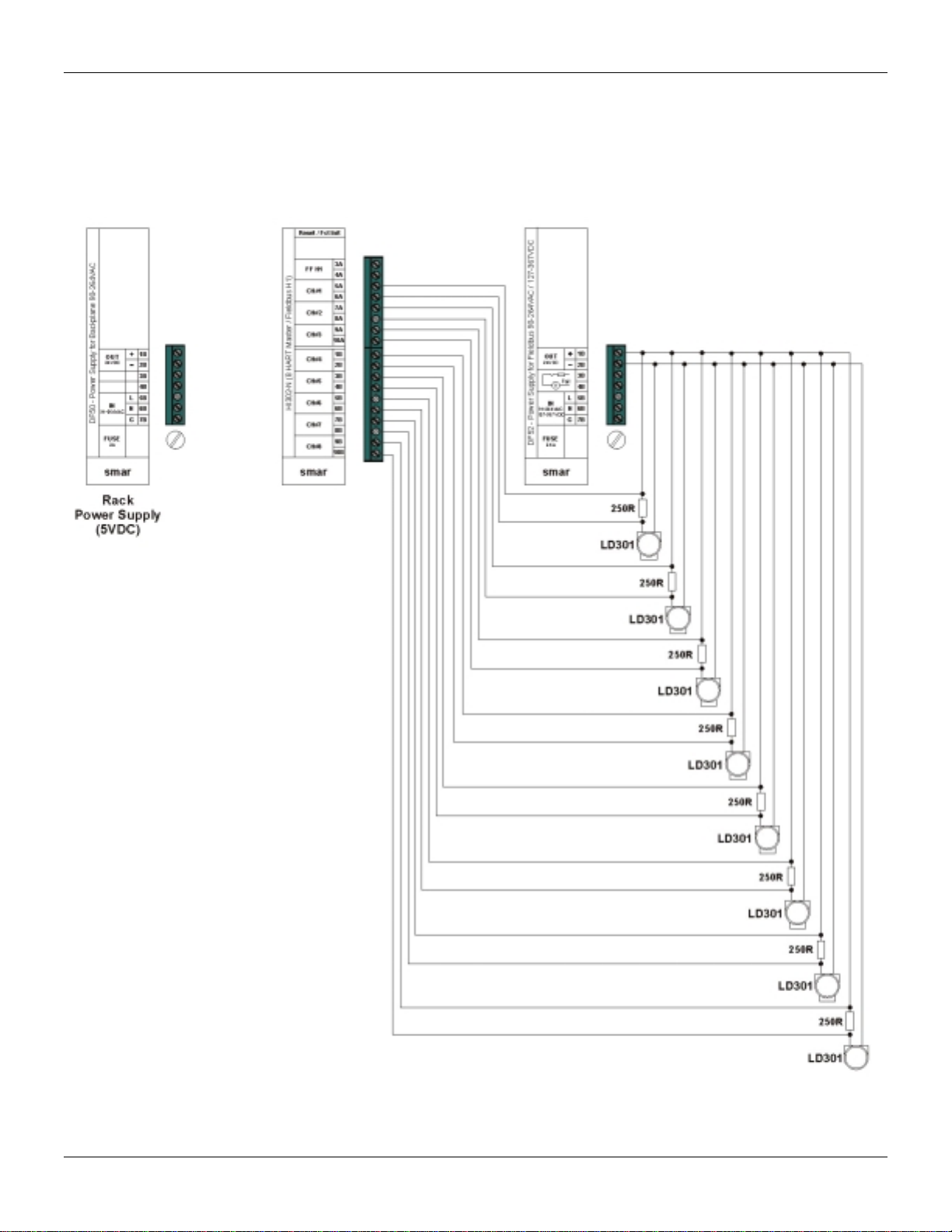
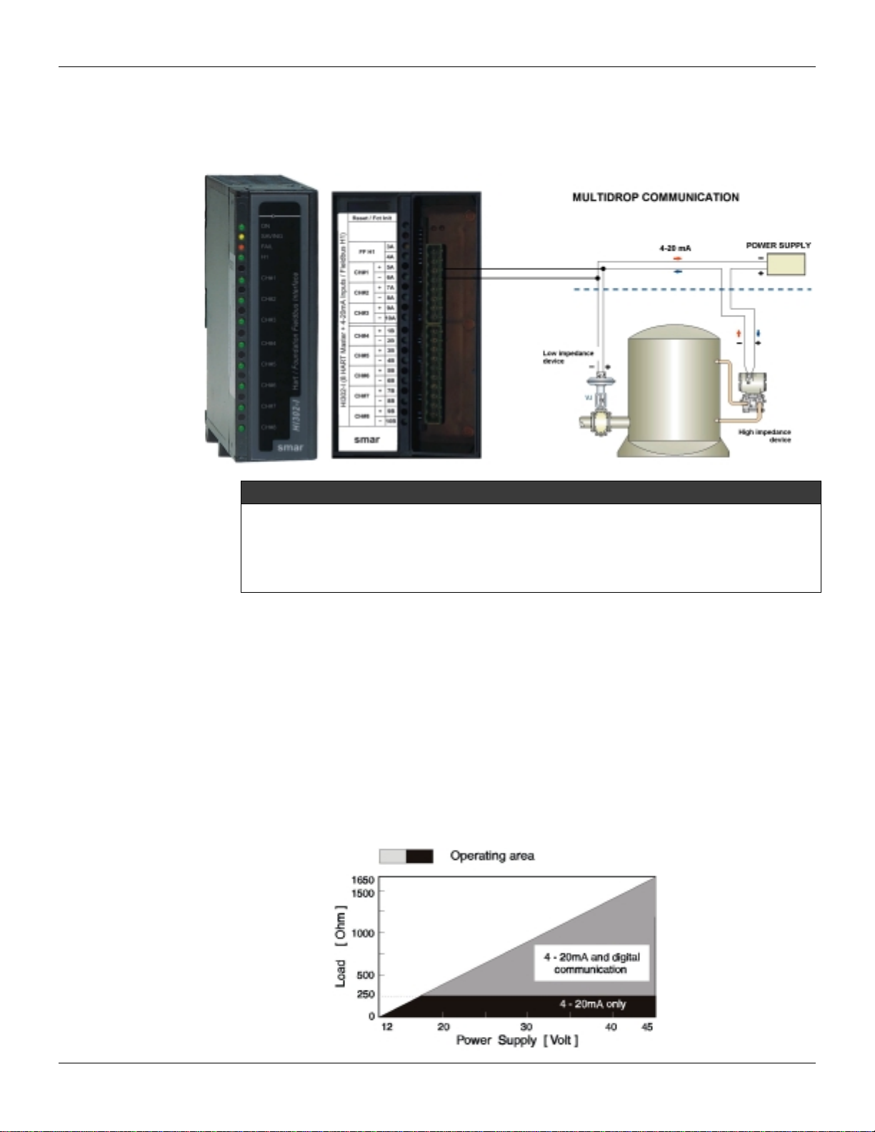
The following picture shows an example of an HI302-N connection focused on the HART
communication. In this case, connect more devices, up to 32, in parallel, to perform a
multidrop communication. In order to simplify the connection below, connect the HART
channel in parallel to the device, instead of connecting it in parallel to the resistor. Doing
so, a common grounding should be used to decrease the wiring length. The connection
below makes the channel independent from the device’s power supply.

Installation
2.4
NOTE
The 250Ωresistor (see the previous picture) in series with each equipment is the analog input
impedance, for example a PLC’s input, that reads the 4-20 mA signal. If the analog input
impedance is less than 250Ω, connect a lower resistor, so that the association of both
impedances is at least 250Ω.
For instance, suppose that a TT301 is connected to a PLC’s input with an impedance equal to
50Ω. So, connect a 200Ωresistor in series with the device’s feeding in order to enable the HART
communication. The user can also use a 250Ωinstead of a 200Ωresistor.
HART Device Installation
Now we will describe the main communication features regarding the device installation.
For more detailed information about the devices, please read the specific device manual.
Concerning the HART Communication, take into consideration that the superimposition of
a modulated signal on an analog current signal can deteriorate, if some precautions are
not taken. It is important to mention that the HART communication does not affect the 4-
20 mA analog signal, since the average value of a FSK modulated signal is zero. Thus, if
the HART device is already installed, make sure that the minimum impedance (25Ω) is
used and connect the HI302 channel in parallel to the device.
Device Physical Types
Low Impedance Devices
Low impedance devices are typically signaling elements intended to receive current
analog signals or serve as master for a multi-drop network. As an example of a low
impedance device we can mention the FY301.
High Impedance Devices
High impedance devices control current, either as a mean of analog signaling or at a fixed
level in a multi-drop environment. As an example of a high impedance device we can
mention the LD301 and the TT301.
HI302 - User’s Manual
2.5
These concepts are of fundamental importance when connecting different devices. For
example, in the connection shown below, depending on the internal actuator impedance, it
may be necessary to install a resistor in series with the power supply. This is done to
achieve the minimum impedance requirement (25Ω).
IMPORTANT
Whatever the topology used, it is important to keep a 25Ωimpedance. In the previous
picture, it is not necessary to connect an impedance in series with the power supply if
the impedance read by the HART channel is at least 25Ω. In case the impedance is
lower than 25Ω, improve its value to the minimum requirement. The connection above
allows the communication between the two devices.
HART Installation Topology
The HI302 comply with several applications, since the new ones to older installations,
where it is necessary to increase the HART device’s life span and preserve the
investment with the gradual introduction of the Foundation Fieldbus technology. Below are
some examples of connections. However, the applications are not limited to these
examples and should be considered separately.
Supply Voltage X Total Loop Impedance
The total impedance of the devices connected to a pair of cables and the cable
impedance should be between the operation limits complying with the loop supply voltage.
See the next graphic:
Installation
2.6
Notice that it is very important to keep the minimum impedance (25Ω) to allow HART
communication. Sometimes the voltage supply must be increased to ensure that the
system is in the operation area.
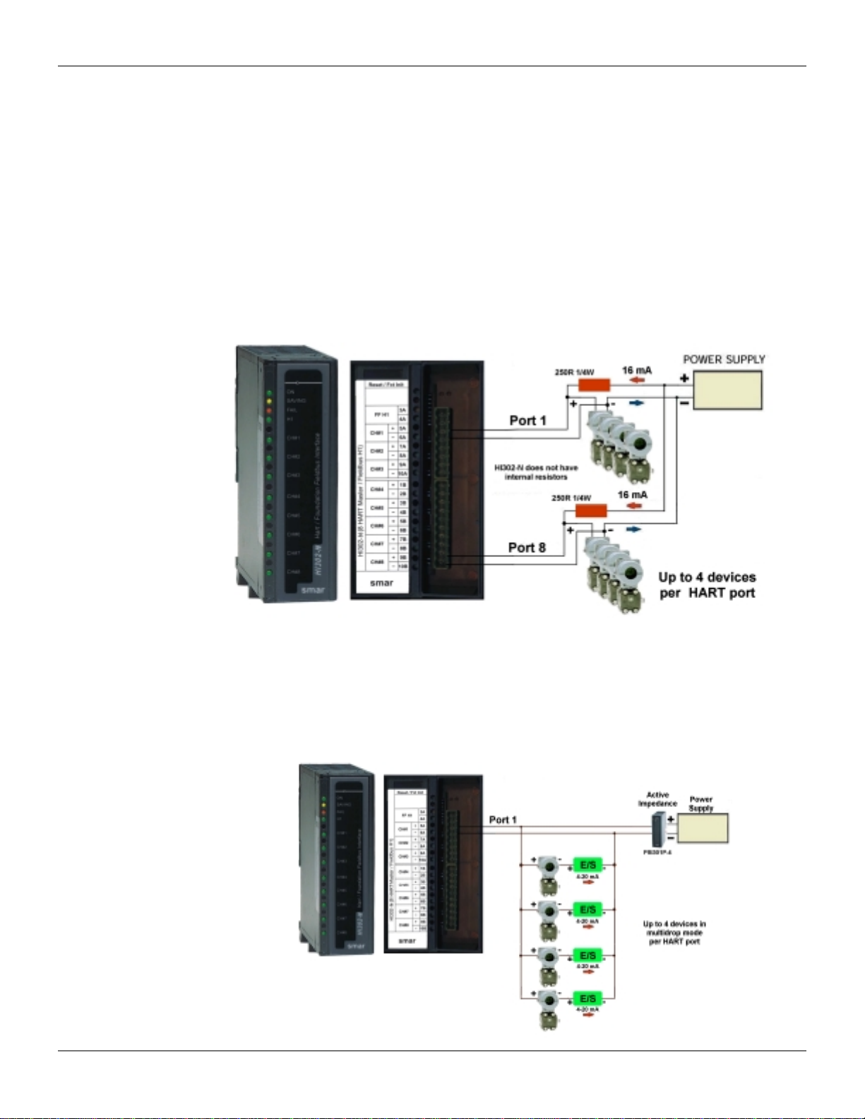
HI302-N (without Analog Conversion)
This HI302 option has only HART communication and no circuit for analog conversion.
The HI302-N does not have an internal resistor, so use an external resistor or an active
impedance (PSI301) if many devices are used.
•Typical Multidrop
There are two ways to perform this connection. The resistor can be installed in series with
the power supply or in parallel to the HART channel. The first way is shown below:
•Multidrop with 4-20 mA enabled
Be careful with this topology because some types of I/O devices do not accept the
connections presented below, for example, the SDCS’s that feed the devices via internal
power supply. The I/O device must receive external feeding, like PLC cards or field
devices. Besides its complexity, this connection allows an improvement in the use of the
HI302 channels and, as the current that flows in the loop is tenths of mA, use an active
impedance instead of a simple resistor. See the next picture:
HI302 - User’s Manual
2.7
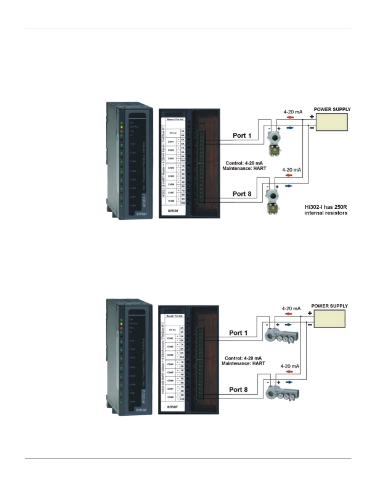
HI302-I (4-20 mA to FF Conversion)
This kind of topology doesn’t have necessarily the 250Ωexternal resistor connected in
series with each device, since there is a 4-20 mA sampling resistor on the HI302 analog
board serial to the loop. Be careful with a short-circuit in the loop, because the HI302’s
internal resistor may be damaged. The HI302 does not have internal protection against
short-circuit.
HI302-O (FF to 4-20 mA Conversion)
It is not necessary to use a resistor in series with the power supply in this topology,
because the device internal impedance and the actuator impedance ensures the minimum
requirement for HART comunication. However, the user should watch the minimum supply
voltage required for total impedance (including the wiring impedance). In this topology, the
HI302’s output is protected against short-circuit.

Installation
2.8
Maximum Cable Length
The user may choose from a shielded pair of twisted cables, a multi-pair of cables with a
single shield or a combination of these.
IMPORTANT
The shield can be overlooked if noise in the environment or any other interference do not
affect the communication.
Use a 24 AWG (0,5 mm) cable for lengths up to 5000 ft. For lengths in excess of 5000 ft
use at least a 20 AWG (0,8 mm) cable.
If a cable longer than 500 m is required, make a detailed analysis of the system to avoid
operation failures. According to HFC (HART Communication Foundation), the maximum
cable length depends on:
•The cable’s resistance and capacitance,
•The device’s resistance and capacitance on the HART channel, as well as the
additional equipment.
Due to the complexity of the subject, users should read the HART Foundation
Communication documentation, specially the FSK Physical Layer document.
Other devices in the Loop
The control loop may have additional devices, besides the HI302 and the HART devices.
See some common types as follow.
Portable Configurator
As we mentioned before, the HI302 operates as a master in most applications. So, there
is no problem in using a portable configurator, such as a HP301. Whatever the installation
topology, make sure to install a 25 Ohms impedance serial to the power supply. If no
active impedance or resistors are installed, the secondary master device will not
communicate.
Indicators and Converters in general
Indicators and converters are very common in industrial installations. They usually have
high impedance in the HART communication frequency (1200 to 2200 Hz). Sometimes
the introduction of such elements in the loop can prevent communication. However, there
is a simple and well known solution for this problem, by connecting a capacitor ranging
from 0.1 to 1µF (100v at least) parallel to the device. This capacitor supplies an
impedance of hundreds Ohms parallel to the device’s impedance, allowing the HART
communication.
Switching On the HI302
When you turn on the module, the system will check some important hardware and
software components. If any errors are found, the module will not operate and the
FAILURE LED (red LED) will light..The HART LEDs (green LEDs) will blink slowly around
¼ Hertz. This check takes approximately 1 minute, so you should wait before checking
the HI302 in the Live List or watch for any value.
HI302 - User’s Manual
2.9
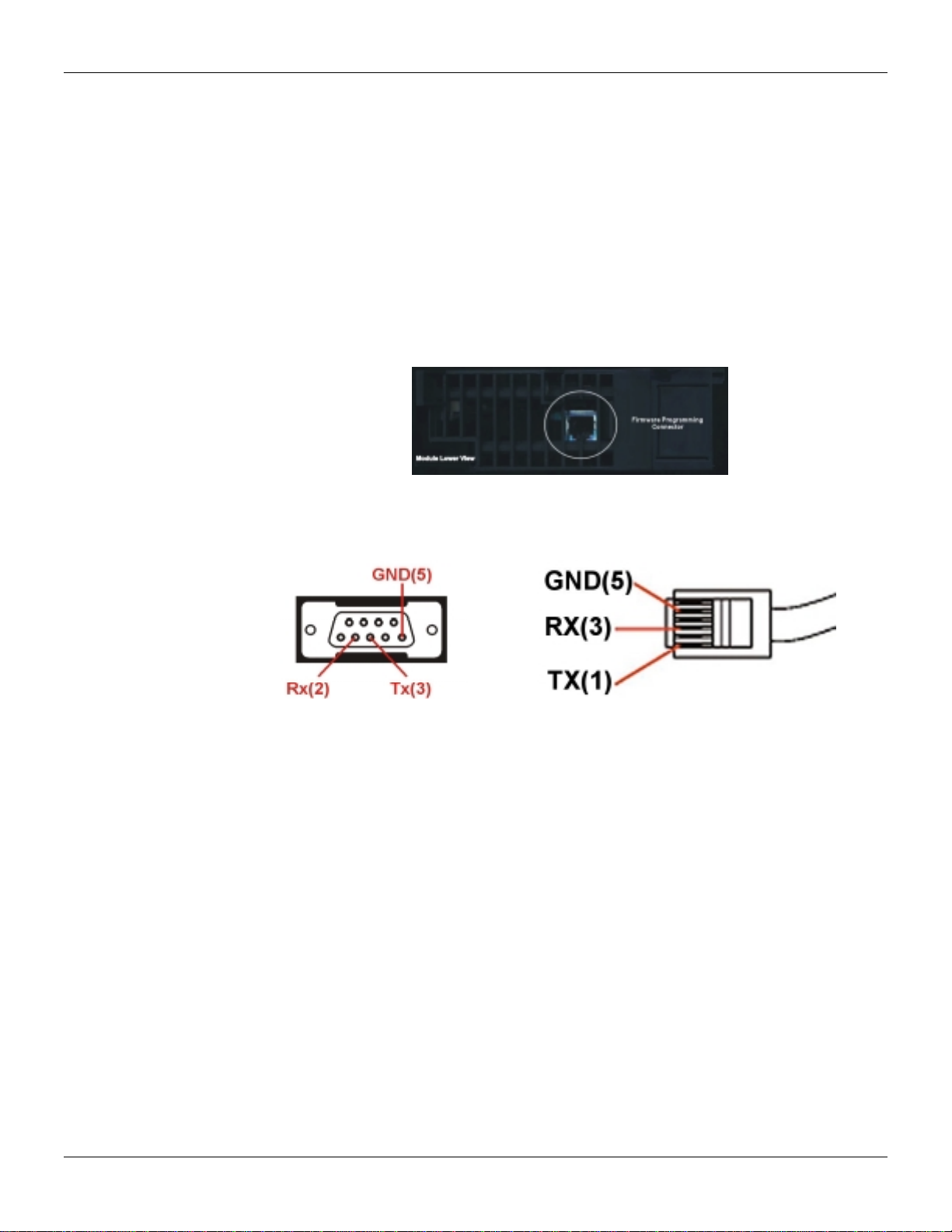
Updating the HI302 Firmware
To update the HI302 firmware you must use the FBTools program built in the System302
as an integral part of it. To do so, connect the RS232 serial cable to the firmware
download connector located behind the module.
Before you begin the update, the HI302 module must be set in the boot loader mode. To
do so, press the Reset button located at the upper right side in the front part of the
module. By pressing it, the FAILURE LED (red LED) will light. Then click the download
button in the Serial Download program and wait for the end of the process.
After the completion of the update process, press the Reset button again, in order to put
the module back in normal operation.
Firmware Programming Connector
RS232 Serial Cable Connector for Firmware Download, DB09F and RJ11M.

Installation
2.10
Other manuals for HI302
1
Table of contents
Other SMAR Recording Equipment manuals


