SMAR PCI302 Manual
P C I 3 0 2 O M M E
MAR / 03
Version
1.1 / 1.2 / 2.0
,
Foundation Fieldbus www.esma-rt.ru

web: www.esma-rt.ru
www.esma-rt.ru
Specifications and information are subject to change without notice.
Up-to-date address information is available on our website.
smar

Table of Contents
III
Table of Contents
INTRODUCTION............................................................................................................................................. 1
General Features ..........................................................................................................................................................2
Powerful Hardware Architecture.................................................................................................................................................. 2
Open Software Architecture......................................................................................................................................................... 2
Easy Installation & Expansibility .................................................................................................................................................. 2
Fieldbus Link Master.................................................................................................................................................................... 2
Process Supervision.................................................................................................................................................................... 2
Flexible Bridge............................................................................................................................................................................. 2
Upgradeable Firmware ................................................................................................................................................................ 2
Isolated Passive Fieldbus MAU................................................................................................................................................... 2
Description....................................................................................................................................................................2
Hardware Overview ......................................................................................................................................................3
CPU (Central Processing Unit).................................................................................................................................................... 4
DP (Dual Port RAM) .................................................................................................................................................................... 4
Control Logic................................................................................................................................................................................ 4
PC Bus (Computer Expansion Bus)............................................................................................................................................. 4
Local Bus (High Speed Wide Bus)............................................................................................................................................... 4
Peripheral Bus............................................................................................................................................................................. 4
Timer0 - 5....................................................................................................................................................................................... 4
Modem0 - 3 (Fieldbus Communications Controller) ....................................................................................................................... 4
MAU0 - 3 (Fieldbus Medium Attachment Unit) ............................................................................................................................... 4
NVRAM (Non-Volatile Random Access Memory)........................................................................................................................ 4
Software Overview........................................................................................................................................................5
HMI (Human-Machine Interface).................................................................................................................................................. 5
PCI OLE Server........................................................................................................................................................................... 5
PCI302 Device Driver .................................................................................................................................................................. 5
DP (Dual Port RAM) .................................................................................................................................................................... 5
CH0 - 63 (PCI302 Fieldbus ports 0 - 63)......................................................................................................................................... 5
PCI3021/8 (Process Control Interface 1 to 8)................................................................................................................................ 5
Interfacing with HMI (Human-Machine Interface)......................................................................................................5
PCI302 Technical Specifications.................................................................................................................................6
PC Bus......................................................................................................................................................................................... 6
CPU............................................................................................................................................................................................. 6
Memory........................................................................................................................................................................................ 6
Fieldbus Interface........................................................................................................................................................................ 6
General........................................................................................................................................................................................ 6
Physical Dimensions.................................................................................................................................................................... 6
APPENDIX A................................................................................................................................................... 7
DIP Switches and LEDs................................................................................................................................................7
PCI302 Version 1.xx.................................................................................................................................................................... 7
PCI302 Version 2.0...................................................................................................................................................................... 7
APPENDIX B................................................................................................................................................... 8
Physical Dimensions....................................................................................................................................................8
PCI302 Version 1.1x.................................................................................................................................................................... 8
PCI302 Version 1.2x.................................................................................................................................................................... 8
PCI302 Version 2.0...................................................................................................................................................................... 9
APPENDIX C................................................................................................................................................. 10
SC71 Cable Specification...........................................................................................................................................10
PIN Description.......................................................................................................................................................................... 10

PCI302 - Operation & Maintenance Instructions Manual
IV
APPENDIX D................................................................................................................................................. 11
Installation...................................................................................................................................................................11
Hardware Configuration.............................................................................................................................................11
PCI302 V2.0 .............................................................................................................................................................................. 11
PCI302 V1.xx............................................................................................................................................................................. 11
Hardware Installation .................................................................................................................................................12
PCI302 V2.0 .............................................................................................................................................................................. 12
PCI302 V1.xx............................................................................................................................................................................. 12
Software Installation.................................................................................................................................................................... 12
Updating the Firmware ................................................................................................................................................................ 13
APPENDIX E – SRF – SERVICE REQUEST FORM...................................................................................E.1
APPENDIX F - SMAR WARRANTY CERTIFICATE....................................................................................F.1

PCI302 - Operation & Maintenance Instructions Manual
1
PCI302 - PROCESS CONTROL INTERFACE
Introduction
The PCI302 (Process Control Interface) is a high performance Fieldbus interface that combines
advanced process control with multiport communications management.
PCI302 is a card designed to work inside industrial or commercial PCs. Featuring independent
Fieldbus H1 (31.25Kbps) master ports and powered by a 32-bit RISC CPU. Directly connected to
the PC bus (through PCI bus or ISA bus), it provides a fast communication path between the
Fieldbus and PC applications.
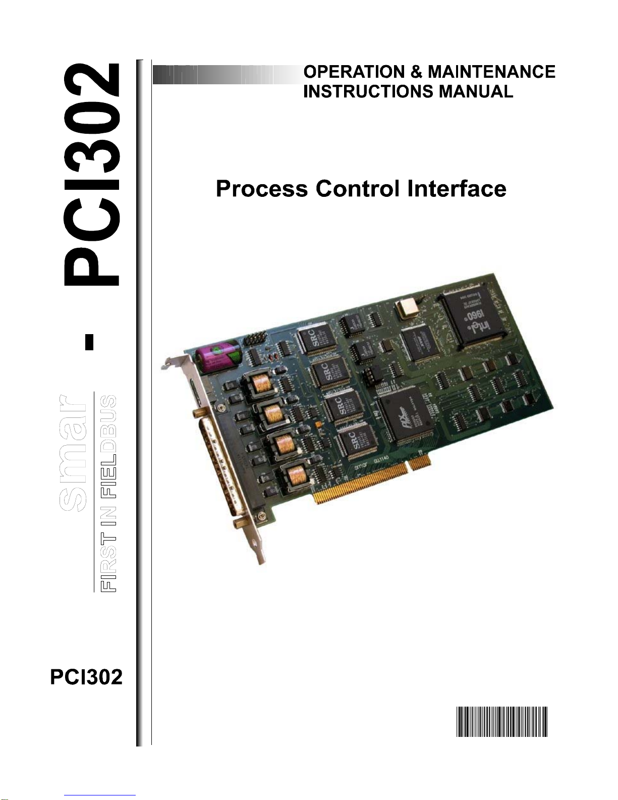
Figure 1 - Perspective View of a PCI302 card Version 1.1x.
Part Number
PCI302 Process Control Interface
INDUSTRIALRACK
COMPATIBLE
500VAC
FIELDBUSESISOLATION
SMARDEDICATED
FIELDBUSMODEMS
HIGHPERFORMANCE
32bitRISCCPU
FULL32bit
ARCHITECTUREHIGHSPEED
DUALPORTRAM16BitISABUS

PCI302 - Operation & Maintenance Instructions Manual
2
General Features
Powerful Hardware Architecture
The 32-bit super-scalar RISC CPU and dual port memory based architecture ensure high
processing power to PCI302. All communication and process control tasks are internally executed,
keeping the PC free to implement the best HMI and the Smar PCI OLE Server.
Open Software Architecture
The PCI OLE Server interconnects one or more simultaneous client applications with Fieldbus
interfaces. Clients can access the server located on the same PC or on a remote through
LAN/WAN. This enables the same distributed Fieldbus database to be widely shared among
workstations.
Easy Installation & Expansibility
The PCI302 PCI (Peripheral Component Interconnect) bus version can be easily installed. (PCI bus
specification v2.1) (*). Unique hardware design allows the installation of up to eight PCI302 cards
(depending on the number of free PCI bus slots) on one PC bus. No board configuration is
necessary for the installation. The PC’s plug and play system allocates the addressing resources for
the board operation.
The PCI302 ISA bus version can also be easily installed on the ISA or EISA bus of any AT-
compatible PC. Unique hardware design allows the installation of up to eight PCI302 cards
(depending on the number of free ISA slots) on one PC bus, sharing the same I/O port and interrupt.
Fieldbus Link Master
The PCI302 can manage each of its Fieldbus ports as a link master device.
Process Supervision
Exploring advanced communication features of the Fieldbus protocol, the PCI302 can be used as an
efficient supervision interface. The function block parameters of field devices can be monitored
(cyclic or acyclic reads) or actuated (acyclic writes) through the PCI302 supervision services. HMIs
like supervisory systems and configurators, running on the host PC, can interface to the PCI302s,
keeping complete hardware and Fieldbus protocol transparency.
Flexible Bridge
The PCI302 open software architecture enables data sharing between independent Fieldbus ports.
Upgradeable Firmware
PCI302's firmware (on-board executable program) remains in FLASH memory. As these memories
are in-circuit programmable, the user can change the PCI302 firmware (upgrade software release,
change protocol, etc.) without removing components - just run the FBTools utility and everything is
done by software.
Isolated Passive Fieldbus MAU
Its galvanically isolated Medium Attachment Unit is passive (not powered by the Fieldbus network).
This enables the user to plug any PCI302 port on a fully loaded Fieldbus.
Description
At both, hardware and software levels, the PCI302 card was designed to handle all necessary
communication and process control tasks, minimizing the PC overload.
Typical Applications
The PCI302 can be used in a wide range of Fieldbus-based applications. The next figure shows a
generic Field Control System from which many real applications can be derived.
*See note page 16.
PCI302 - Operation & Maintenance Instructions Manual
3
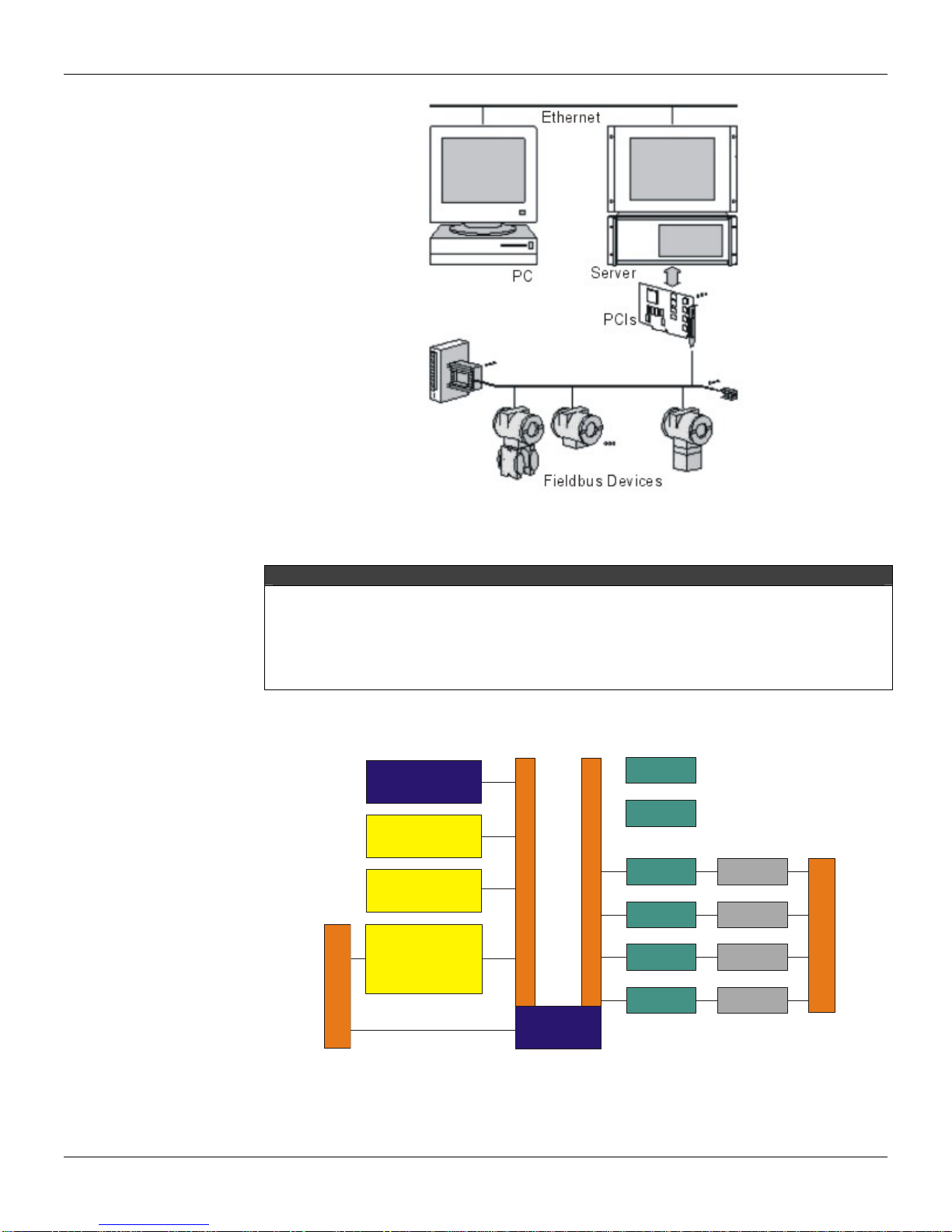
Figure 2 - Fieldbus Typical Application using PCI302 cards.
Remarks
•1 to 8 PCI302 cards can be installed in the same PC Server.
•Up to 4 ports in each PCI302 Fieldbus line connected.
•Redundant operation (1 to 4 PCI302s on each Fieldbus, distributed on different PCs).
•Fieldbus configuration, management and supervision.
•Network access via Ethernet (Client/Server architecture via DCOM).
Hardware Overview
Figure 3 – PCI302 Hardware Diagram.
P
C
B
U
S
F
I
E
L
D
B
U
S
CPU
CONTROL
LOGIC
TIMER
0.2
TIMER
3.5
MODEM
0
MODEM
2
MODEM
1
MODEM
3
MAU
0
MAU
2
MAU
1
MAU
3
FLASH
NVRAM
DP
L
O
C
A
L
B
U
S
P
E
R
I
P
H
E
R
A
L
B
U
S

PCI302 - Operation & Maintenance Instructions Manual
4
CPU (Central Processing Unit)
A 32-bit super-scalar RISC processor that handles all communication and control tasks performed
by the PCI302.
DP (Dual Port RAM)
16-bit data memory shared with the PC through the PC bus. Both PCI302 and PC CPUs have
simultaneous access to this memory, providing an efficient communication path between them.
Control Logic
Internal control logic to handle the CPU access to all devices (RAM, NVRAM, FLASH, TIMERs,
MODEMs), and the DP arbitration mechanism.
PC Bus (Computer Expansion Bus)
A PCI bus (specification v2.1) (*), 16-bit ISA or 32-bit EISA bus, on which the PCI302 cards are
plugged. It provides power and PC access to the card.
Local Bus (High Speed Wide Bus)
A 32-bit internal bus that interconnects the CPU to fast devices (RAM, NVRAM, FLASH and DP).
Peripheral Bus
8-bit peripheral bus used by the CPU to connect to slow devices (TIMERs and MODEMs).
Timer0 - 5
8/16-bit 3-channel universal timers, used by the PSM-Real Time Kernel as a time base for task
switching and the Fieldbus communication timing.
Modem0 - 3 (Fieldbus Communications Controller)
The Smar Fieldbus chips that serialize the data communication at a 31.25Kbps baud rate. It is ISA-
SP50 Fieldbus Physical Layer Specification compliant.
MAU0 - 3 (Fieldbus Medium Attachment Unit)
A signal conditioning and isolation circuit that adapts the digital signal (0/5V) from the modem to the
Fieldbus lines, according to the ISA-SP50.02-1992 Fieldbus Physical Layer Specification. The
PCI302 MAU is passive, that is, not powered by the bus.
NVRAM (Non-Volatile Random Access Memory)
The 32-bit data memory is where the PCI302 data structures and objects are stored.
FLASH (Flash Memory)
32-bit code memory, where the PCI302 program is stored.

PCI302 - Operation & Maintenance Instructions Manual
5
Software Overview
Application
Clients SYSCON
OLE DCOM
PCI OLE Server
0
PCIs
FIELDBUS
PC
Server
00
11 1
22 2
333
PCI NT Device Driver
PCI
1
PCI
7
PCI
0
FBTOOLS
Figure 4 – PCI302 Hierarchy Layers.
HMI (Human-Machine Interface)
User application program (configurator, supervisory, analyzer, etc.) running on PC(s) and interfacing
with the PCI302 card through a specific server for the services.
PCI OLE Server
Server for PCI302s based on Client/Server architecture, providing a consistent set of functions for
Supervision and Configuration. It standardizes and simplifies the HMI access to the hardware.
PCI302 Device Driver
Specific hardware driver for Windows NT and 2000 Operating System, implementing effectively the
access to local PCI302s.
DP (Dual Port RAM)
Memory shared by the PCI302 and PC, at hardware and software levels, which contains all
structures required for data and command transfer between them.
CH0 - 63 (PCI302 Fieldbus ports 0 - 63)
The card independent ports, running inside the PCI302. Each one includes the Physical layer and
part of the Data Link layer.
PCI3021/8 (Process Control Interface 1 to 8)
A maximum of 8 PCI302 cards may coexist in a PC bus, totaling 32 ports.
Interfacing with HMI (Human-Machine Interface)
A generic HMI (Human-Machine Interface), like supervisory systems, configurators, etc., interfaces
with Smar Fieldbus devices through the PCI302 card, using the PCI OLE Server specification. The
generic HMI may work under Windows 95, NT and 2000.
The PCI OLE Server is a 32-bit version server for Windows NT (in compliance with OPC - OLE for
Process Control specification). This enables OPC clients to supervise the Fieldbus system through
Smar interfaces, in a standardized way (without specific drivers).
For other platforms (OS/2, QNX, etc.), system integrators may also write drivers that access the
PCI302 directly, since Smar provides no drivers for them.

PCI302 - Operation & Maintenance Instructions Manual
6
PCI302 Technical Specifications
PC Bus
PCI302 Version 1.xx PCI302 Version 2.0
Type ISA (16-bit slot) or EISA PCI (specification v2.1) (*)
Hardware Interrupt IRQ 5, 10, 11, 12 or 15 none
I/O Port Base 240H, 280H, 300H or 340H Plug and Play allocation
I/O Port Area 48 contiguous bytes 48 contiguous bytes (interface)
80 contiguous bytes (configuration)
I/O Access 16-bit 16-bit
Dual Port RAM (I/O accessed) 256KB, 16-bit 256KB, 16-bit
CPU
PCI302
Type 32-bit RISC
Sustainable Performance 50 MIPS
Peak Performance 75 MIPS
Memory
PCI302 Version 1.1x PCI302 Versions 1.2x and 2.0
Code Area 1MB, 32-bit Flash Memory
(Upgradeable firmware) 1MB, 32-bit Flash Memory
(Upgradeable firmware)
Data Area 512KB, 32-bit NVRAM
(Data and configuration retention) 2MB, 32-bit NVRAM
(Data and configuration retention)
Fieldbus Interface
PCI302
Number of ports 4, independents with DMA
Physical Layer Standard ISA-S50.02-1992
Baud Rate 31.25Kbps (H1)
MAU Type Passive (not bus powered)
Intrinsic Safety NOT compliant
Isolation 500 VAC (each port)
Connector 37-pin D-SUB, male
General
!!!!!!!!!!!!!!!!!!!!! PCI302 VERSIONS 1.XX PCI302 Version 2.0
Operating Conditions 0ºC to +50 ºC @ 5% to 90% RH 0 ºC to +50 ºC @ 5% to 90% RH
Non-operating Conditions -30 ºC to +70 ºC @ 5% to 90% RH -30ºC to +70ºC @ 5% to 90% RH
Operating Voltage +5V ±5% +5V ±5% and +3.3V ± 10%
Operating Current 1.2A (typ) 1.19A (typ) / +5V Power Supply
0.085A (typ) / +3.3V Power Supply
Physical Dimensions
PCI302 Version 1.1x PCI302 Version 1.2x PCI302 Versions 2.0
Standard ISA 16-bit ISA 16-bit PCI bus
External Dimensions 173.0 x 21.6 x 141.6mm (max)
6.85 x 0.85 x 5.57" 194.5 x 21.6 x 141.6 mm (max)
7.65 x 0.85 x 5.57" 234.9 x 21.6 x 125.0 mm (max)
9.25 x 0.85 x 5"

Appendix A
7
DIP Switches and LEDs
PCI302 Version 1.xx
W1 W2 W3 Card W4 W5 I/O PORT
0 0 0 0*0 0 240 - 26FH
0 0 1 1 0 1 280 - 2AFH*
0 1 0 2 1 0 300 - 32FH
0 1 1 3 1 1 340 - 36FH
1 0 0 4
1 0 1 5 W6 NVRAM BATTERY
1 1 0 6 0 ON (data retention)
1 1 1 7
1 OFF (data loss)*
0 = ON = LOWER POSITION
1 = OFF = UPPER POSITION
* = Factory default setting
Table 1 – PCI302 1.xx Dip Switches.
NOTES
The interrupt (IRQ5, IRQ10, IRQ11, IRQ12 or IRQ15) is software configured with the FBtools or
ItfSetup programs.
WARNING!
The switch W6 (NVRAM BATTERY) is factory set to the OFF position in order to avoid energy loss
while the card is at Smar`s stock or on the Customer’s shelf. BEFORE USING THE PCI302 V1.xx,
THE DIP6 SHOULD BE TURNED ON.
PCI302 Version 2.0
LED Color Name Description
1 Red FAIL When ON, it indicates reset condition or CPU failure.
2 Green Dual Port
When blinking, it indicates communication through the
Dual Port.
3 Green FF H1-1 Indicates transmission through the first H1 port.
4 Green FF H1-2 Indicates transmission through the second H1 port.
5 Green FF H1-3 Indicates transmission through the third H1 port.
6 Green FF H1-4 Indicates transmission through the fourth H1 port.
Table 2 – PCI302 2.00 LEDs.
Appendix B
8
Physical Dimensions
PCI302 Version 1.1x
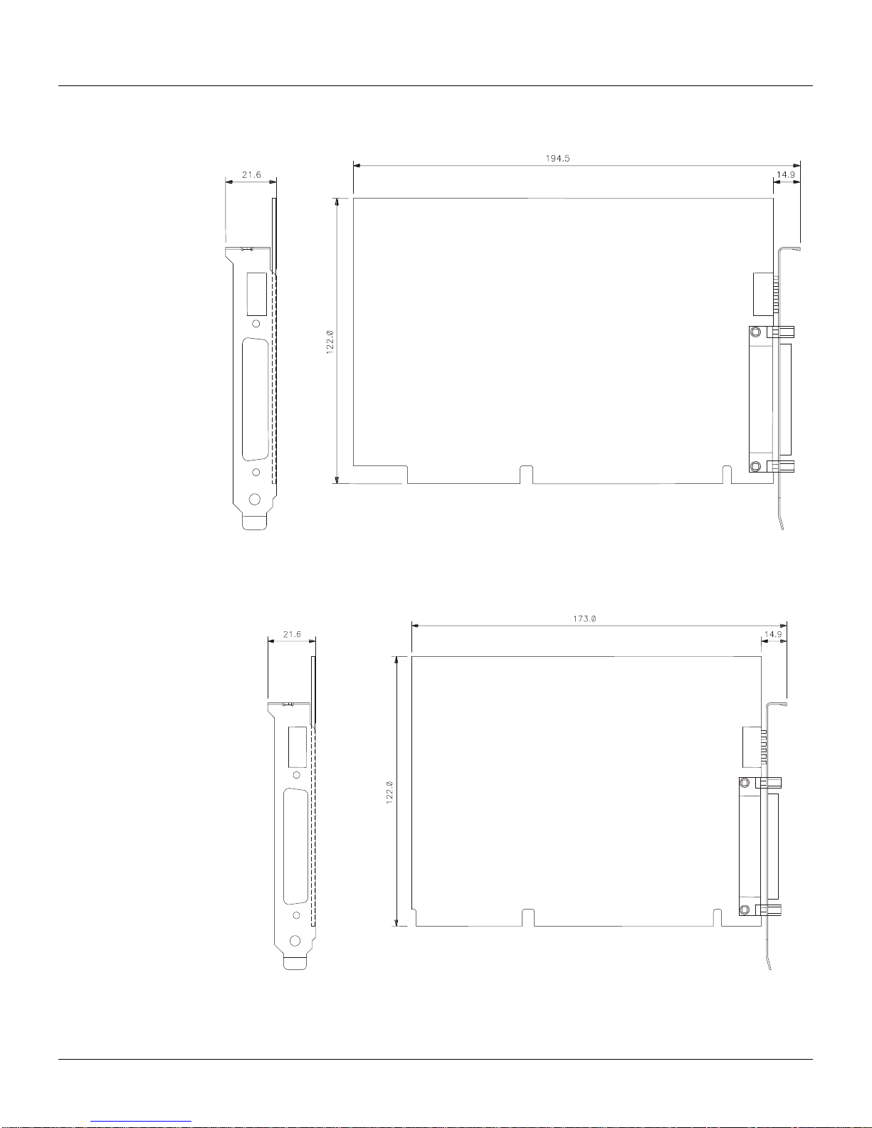
Figure 5 - PCI302 card V1.1x Physical dimensions (mm).
PCI302 Version 1.2x
Figure 6 - PCI302 card V1.2x Physical dimensions (mm).

PCI302 - Operation & Maintenance Instructions Manual
9
PCI302 Version 2.0
Figure 7 - PCI302 card V2.0 Physical dimensions (mm)

Appendix C
10
SC71 Cable Specification
PIN Description
1 Signal 2
18 0DATA+ 0D+
36 0DATA- 0D-
16 1DATA+ 1D+
34 1DATA- 1D-
14 2DATA+ 2D+
32 2DATA- 2D-
12 3DATA+ 3D+
30 3DATA- 3D-
NC GND (shield) GND
Table 1 - SC71 Pin Description
Figure 8 - SC71 Pin view.
Appendix D
11
Installation
Any user can do the PCI302 hardware and software installation quite easily, with a reasonable
knowledge in Fieldbus and PCs.
Hardware Configuration
PCI302 V2.0
No hardware configuration is necessary for PCI302 V2.0.
PCI302 V1.xx
The first step is to verify the PC settings and identify the I/O address and the available interruptions
for the PCI302 v1.xx card.
IMPORTANT
All of the PCI302 cards installed in the PC bus must be set with the same I/O port and same IRQ,
but each one of them with a different card number. The I/O and IRQ of the PCI302 must not
conflict with all the other cards (besides PCI302s) already installed in the PC.
Select a card number (usually starting from 0) to each PCI302 card to be installed in the PC. Take
note of each card and its respective serial number.
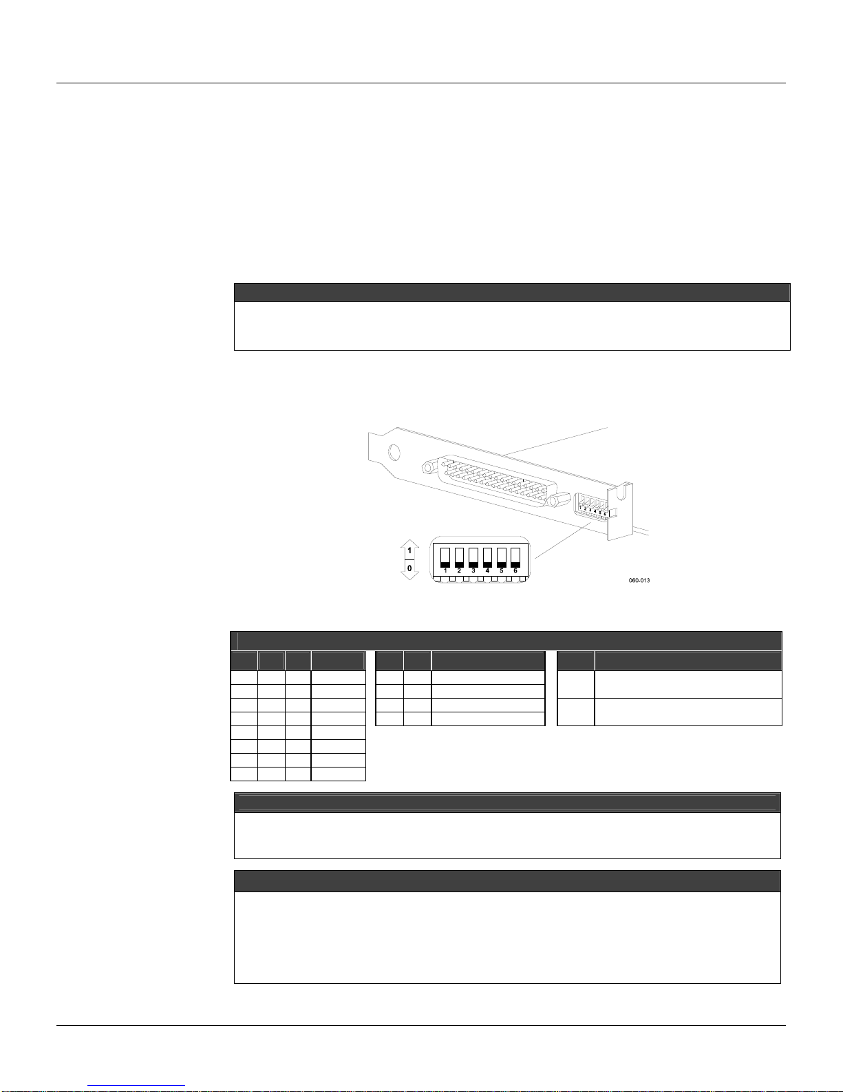
The PCI302 hardware is set through the dip switches located in the back of the card (see figure 9).
FY1PM105.CDR
Figure 9- Dip Switches of PCI302 v1.xx card
PCI302 DIP SWITCHES
W1 W2 W3 CARD W4 W5 I/O W6 NVRAM BATTERY
0 0 0 0* 0 0 240- 26FH 0 ON
0 0 1 1 0 1 280- 2AFH* DATA RETENTION
0 1 0 2 1 0 300- 32FH 1 OFF*
0 1 1 3 1 1 340- 36FH DATA LOSS
1 0 0 4
1 0 1 5
1 1 0 6
1 1 1 7 *FACTORY SETTINGS
ATTENTION
The Dip switches have external access even after the card have been installed in the PC. The
user can change its positions while the PC is on, but NEVER when an application in the PC that
accesses the PCI302 is running.
NOTES
1- In some PCs, IRQ15 is reserved for the secondary HDD control. In case it is necessary to
free the IRQ15 to use in the PCI302s, disable this controller (when not in use), running the PC
setup.
2- The IRQ 12 is usually saved for the mouse PS/2.
3- The PCI302 v1.2 interruption (IRQ5, IRQ10, IRQ11, IRQ12 or IRQ15) is set via tool software
FBtools or ItfSetup.

PCI302 - Operation & Maintenance Instructions Manual
12
IMPORTANT
The W6 Dip_Switch (NVRAM battery) is set in factory to OFF, in order to avoid energy loss while
the card is kept in stock in the Smar’s installations or Customer’s installations. The W6
DIP_Switch must be turned ON before using the PCI302 V1.2
Hardware Installation
PCI302 V2.0
First, install the SYSTEM302 with the PCI302 V2.0 option, then, connect the PCI302 V2.0 to the
computer. Thus, all of the Windows installation procedures will be performed automatically.
If the SYSTEM302 is not installed and a PCI302 V2.0 is connected to the PC, the Windows program
will request a device driver for the PCI302 V2.0. In this case, insert the SYSTEM302 installation CD
and instruct the Windows’ Hardware installation program to install the device driver through the
CD_ROM.
PCI302 V2.0 can be easily installed in the PCI bus (specification v2.1) (*) of every commercial or
industrial PC. Refer to the computer manual for instructions on how to install and remove PCI cards.
Turn off the PC before inserting or removing the PCI302s from the bus. There is a limit of up to 8
PCI302 cards in the PC bus.
NOTES
For appropriate refrigeration to the PCI302 cards keep the PC cabinet closed while it is ON.
The PCI302 V2.0 is not compatible with PCI302 V1.xx. The two types of cards can be physically
installed on the same computer but just one will work with the SYSTEM 302.
PCI302 V1.xx
After the hardware configuration, turn on your PC again and check the functionality of all the
hardwares installed in your PC to detect possible conflicts after the installation of the PCI302. If
there is any abnormal operation, start again with the installation procedures.
After the hardware configuration have been done, the PCI302 v1.xx can be installed in the ISA bus
(16 bits slots) or EISA of every commercial or industrial PC. Refer to the computer manual for
instructions on how to install and remove ISA cards. Turn off the PC before inserting or removing
the PCI302s from the bus. There is a limit of up to 8 PCI302 cards in the PC bus.
NOTES
For appropriate refrigeration to the PCI302 cards. Keep the PC cabinet closed while it is ON.
The PCI302 V1.0 is not compatible with PCI302 V1.2. In case it is necessary to install the PCI302
V1.0 and V1.2 in the same PC, please contact Smar Technical Support and make a request to
exchange the PCI302 V1.0 for PCI302 V1.2.
PCI302 V1.1 is fully compatible with PCI302 V1.2.
Software Installation
During the SYSTEM302 installation process, a dialog box will appear requesting the type of PCI302
to be used (versions between 1.x and 2.0) or not to use a PCI302.
The option chosen by the user can be changed later by using the Interface Setup (ItfSetup) program
of the SYSTEM302.
Please refer to the System 302 documentation for more details.
PCI302 - Operation & Maintenance Instructions Manual
13
Updating the firmware
ATTENTION
While downloading a PCI302 firmware, all fieldbus activities in the PCI302 will stop. After the
firmware download is done, it will be necessary to download the PCI302 configuration via Syscon.
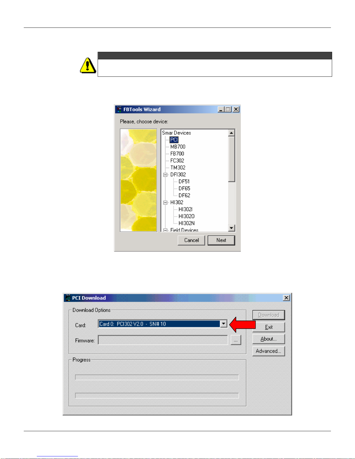
1. Launch the FBTools Wizard, located in the Start menu
Æ
Programs
Æ
System302
Æ
FBTools
Wizard.
2. Select PCI and click Next.
3. Select the desired PCI card.
PCI302 - Operation & Maintenance Instructions Manual
14
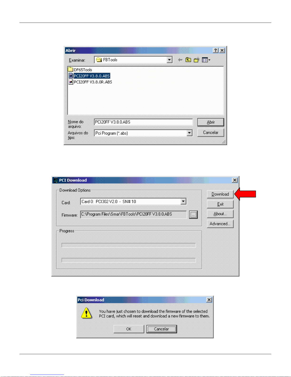
4. Click the Browse... button to select the firmware file to be downloaded (PCI*.abs file).
5. After selecting the firmware file, the Download button will be enabled. Click on it to initiate the
firmware download.
6. A message box will come up requesting a confirmation. Click Ok to continue.
PCI302 - Operation & Maintenance Instructions Manual
15
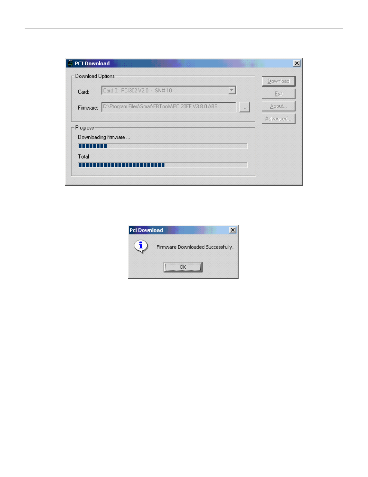
7. The progress bar at the bottom of the dialog box will show the progress of the operation.
8. When the download is complete, a dialog box will appear confirming that the program was
downloaded successfully. Click OK and wait a few minutes while the information is updated.
9. Click Close to exit the PCI Download dialog box.

PCI302 - Operation & Maintenance Instructions Manual
16
NOTE (*)
PCI302 v2.0 card follows PCI bus specification version 2.1. However it is recommended to be
used on PCI bus specification version 2.2 systems.
To operate on a PCI v2.1 specification system, the 5 volts keyed PCI connectors must provide 3.3
volts power. This characteristic is optional in PCI 2.1 specification but many of such systems
provide 3.3 volts on all connectors. In PCI 2.2 specification this 3.3 volts supply is a requirement.
Therefore PCI302v2.0 operates normally on PCI 2.2 specification systems.
To identify the PCI bus specification version, it is necessary to check the PC´s manufacturer
documentation. The PCI specification version 2.2 was released in December of 1998. Since then,
many PC systems have been built PCI bus specification 2.2 compliant.
Table of contents
Other SMAR Recording Equipment manuals


