smart acoustic SMK61 User manual
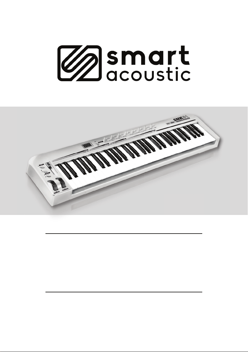
SMK61
CONTROLLER KEYBOARD
USER MANUAL

PAGE
1
CONTENTS
INTRODUCTION .................................2
SMK61 SPECIFICATIONS ..........................2
FRONT PANEL DESCRIPTION .......................3
BACK PANEL DESCRIPTION ........................4
INSTALLATION ..................................4
ASSIGNING THE KEYBOARD USING THE BUILT-IN MULTI
FUNCTIONS: ....................................2
USING THE IN-BUILT FUNCTIONS .............................. 5
CONTROL MENU ........................................... 5
CHANNEL ................................................ 5
PROGRAM ................................................ 6
BANK MSB/BANK LSB....................................... 6
RPN ..................................................... 6
NRPN.................................................... 7
KEYBOARD CURVE ......................................... 7
PEDAL CURVE............................................. 7
RPN/NRPN ................................................ 8
DUAL.................................................... 8
SPLIT.................................................... 8
MUTE ................................................... 8
SNAP SHOT............................................... 9
UPLOAD/DOWNLOAD ....................................... 9
PEDAL POLARITY .......................................... 9
ALL NOTES OFF ........................................... 9
ALL SOUNDS OFF ......................................... 10
RESET ALL CONTROLLERS .................................. 10
GM ON/GM2 ON/GS ON/XG ON............................... 10
APPENDIX OF CONTROLS .................... 11 - 15

PAGE
2
SMK61 SPECIFICATIONS
Multi-functional 61 Key Controller Keyboard
Assignable Components (Slider, Pedal, Pitch Bend, Modulation Wheel, /
Buttons, Knobs)
Driver Free, Plug and Play Support
Compatible with Windows and MAC OS X | OS
Compatible with Major Sequencer Software
USB and MIDI Connection Options
Adjustable Keyboard Velocity, Keyboard curve and external pedal curve.
Any physical controlled (ie. pitch bend, modulation, slider, rotary knobs) can be
assigned to any MIDI function easily.
2 selectable banks of four endless rotary knobs, each assignable to any MIDI
function for use with external MIDI equipment or soft-synths.

PAGE
3
FRONT PANEL DESCRIPTION
1. EDIT: Enables/Disables the keyboard's multi-function. The LED indicates whether it is
on/off.
2.
/KEYBOARD TRANSPOSE BUTTONS: Pressing these buttons transposes the
keyboard up/or down 1 octave at a time. The maximum the keyboard can be transposed
to is +/- 3 octaves. To transpose the keyboard +/- one semitone hold down the edit
button and then press / buttons to the desired setting.
3. BANK: Switches between rotary encoders A1-A8 and B1-B8
4. A1-A8 AND B1-B8 KNOBS: Assignable knobs with an independent channel and
controller distributed to each knob.
5. SLIDER: Assignable fader (works on global MIDI channel).
6. PITCH BEND: Assignable pitch bend wheel (works on global MIDI channel).
7. MODULATION WHEEL: Assignable modulation wheel (works on global MIDI channel).
8. KEYBOARD MULTI-FUNCTION: When in EDIT mode, use keys to program keyboard
and assign controllers.
A1
B1
A2
B2
A3
B3
A4
B4
A5
B5
A6
B6
A7
B7
A8
B8
ASSIGN CHANNEL PROGRAM BANKMSB BANKLSB RPNMSB RPNLSB NRPN MSB NRPNLSB DATAMSB DATALSB KEYBOARD
CURVE
PEDAL
CURVE MUTE SNAPSHOT UPLOAD DUAL SPLIT
DOWNLOAD SPLITPOINT PEDAL
POLARITY
ALLSOUND
OFF
ALLNOTE
OFF
RESETALL
CONTROLLER
GMON GM2 ON GS ON XGON 0 1 2 3 4 5 6 7 8 9 CLEAN ENTER
A
B
1
2
6 7 8
5
3 4

PAGE
4
BACK PANEL DESCRIPTION
1. MIDI OUT: MIDI output interface
(Use this to connect the keyboard to other midi hardware).
2. USB: USB interface
(This will send midi data to computer for use with external sequencer)
3. PEDAL: Assignable pedal interface, for switching or continuous pedal controls
(Works on global midi channel).
4. DC12V: 12V power input jack. Use positive tip 12V DC 500MA adapter.
5. OFF/ON: Power ON/OFF.
INSTALLATION
You can connect the keyboard to a PC or MAC via the USB cable. The system will install
the keyboard driver automatically (the device will register as 'USB Audio Device')
You can connect the keyboard to other devices such as a sound module to transport MIDI
data via the MIDI output port.
It can also be powered by an optional 12V DC power supply (when USB power is not
available).

PAGE
5
ASSIGNING THE KEYBOARD AND
USING THE IN-BUILT FUNCTIONS
The majority of the functions of the keyboard can be easily executed by pressing the grey
EDIT button, followed by a command key under the CONTROL / FUNCTION / RESET
menus, then by entering the desired numerical value using the NUMBER keys, followed
nally by the ENTER key. Once the sequence is completed you should get a “don” (done)
message on the LED display. Please see the ASSIGN example below for a more detailed
explanation.
CONTROL MENU
To assign one of the rotary encoders to CC 7 (Control Change 7 – Volume), proceed as
follows:
Press the EDIT button once
Press the ASSIGN key (under CONTROL menu on keyboard)
Physically move one of the four rotary controls with your hand
Press the key marked “7” under the NUMBER menu on the keyboard
Press the key marked ENTER at the end of the keyboard
CHANNEL
This function is used to set the GLOBAL MIDI channel or a unique MIDI channel for each of
the rotary encoders. The GLOBAL MIDI channel is the default channel that the pitch bend
wheel, modulation wheel, slider fader, expression pedal and rotary knobs are all set to
when the keyboard is sent from the factory. This GLOBAL MIDI channel can be changed
by using the following sequence: EDIT, CHANNEL, NUMBER (enter the MIDI channel you
desire), ENTER. The CHANNEL function can also be used to set a different and unique
MIDI channel for each of the banks of four rotary encoders.
To assign one of the rotary encoders to MIDI channel 3, proceed as follows:
Press the EDIT button once
Press the CHANNEL key (under CONTROL menu on keyboard)
Physically move one of the four rotary controls with your hand\ Press the key marked “3”
under the NUMBER menu on the keyboard.
Press the key marked “ENTER” at the end of the keyboard
* Note – To set any rotary encoder to the GLOBAL midi channel, set it to Channel “0”

PAGE
6
PROGRAM
This function is used to send a program change to an external midi device. To send a
program change enter the following sequence.. EDIT, PROGRAM, NUMBER (enter the patch
/ preset number you desire), ENTER.
* Note – The rst rotary encoder (A1) is already set up to do this function when the
keyboard is sent from the factory.
BANK MSB / BANK LSB
Use this function to send Bank MSB and Bank LSB midi commands to an external
synthesizer for recalling patches. Typically, cc#32 (Bank Select LSB) is used to select a
family (i.e. 1 - SC-55, 100 - MT-32 etc) then cc#0 (Bank Select MSB) is used to set a particular
variation bank.
RPN
GM denes several Registered Parameters, which act like Controllers but are addressed
in a different way. In MIDI, every Registered Parameter is assigned a Registered Parameter
Number or RPN. Registered Parameters are usually called RPNs for short.
Setting Registered Parameters requires sending (numbers are decimal):
1. Two Control Change messages using Control Numbers 101 and 100 to select the
parameter, followed by
2. Any number of Data Entry messages of one or two bytes (MSB = Controller #6, LSB =
Controller #38), and nally
3. An "End of RPN" message
The following global Registered Parameter Numbers (RPNs) are standardised [1] (the
parameter is specied by RPN LSB/MSB pair and the value is set by Data Entry LSB/MSB pair):
0,0 Pitch bend range
1,0 Channel Fine tuning
2,0 Channel Coarse tuning
3,0 Tuning Program Change
4,0 Tuning Bank Select
5,0 Modulation Depth Range
127,127 RPN Null
For example: RPN control sequence to set coarse tuning to A440 (parm 2, value 64):101:0,
100:2, 6:64, 101:127, 100:127

PAGE
7
NRPN
NRPN stands for "Non-Registered Parameter Number" and is part of the MIDI specication
for control of electronic musical instruments. NRPNs allow for manufacturer-specic or
instrument-specic MIDI controllers that are not part of the basic MIDI standard.
Unlike other MIDI controllers (such as velocity, modulation, volume, etc), NRPNs require
more than one piece of controller data to be sent. First, controller 99 - NRPN Most
Signicant Bit (MSB) - followed by 98 - NRPN Least Signicant Bit (LSB) sent as a pair
specify the parameter to be changed. Controller 6 then sets the value of the parameter in
question. Controller 38
may optionally then be sent as a ne adjustment to the value set by controller 6.
This ne adjustment is part of the conventional MIDI controller specication, where any
of the rst 32 controls can be optionally paired with a control offset 32 higher. This is the
rare 14-bit Continuous Controller feature of the MIDI specication, and NRPNs simply take
advantage of that existing option in the same way to offer 16,384 possible values instead of
only 128.
NRPNs allow for MIDI control of a vastly greater number of parameters than the basic 121
set out in the basic MIDI standard.
KEYBOARD CURVE
To change the velocity response curve of all the keys on the keyboard use the following
sequence.. Press the EDIT button, then KEYBOARD CURVE, then a NUMBER value between
1 and 5 (1 being the softest velocity curve and 5 being the hardest), then ENTER.
PEDAL CURVE
You can adjust the PEDAL CURVE to work better with pedals of different specications and
resistance values. If the pedal's range is short, you should turn the PEDAL CURVE up. If the
pedal cannot reach the max or the min, you should turn the PEDAL CURVE down.
You can estimate the pedal curve value by the expressions: PEDAL CURVE = (128* pedal
resistance value) / (10K+pedal resistance value). For instance, if the pedal resistance value
is 10K, then the PEDAL CURVE = 128* 10K/ (10K+10K) = 64. As explained in Section 4.2, any
controller can be used to adjust it if previously assigned to the preset. Adjust it by refering
to ASSIGNING THE KEYBOARD & USING THE IN-BUILT FUNCTIONS (page 5).

PAGE
8
DUAL
When DUAL function is ON, the KEYBOARD/WHEEL/PEDAL/SLIDER sends MIDI messages
to two channels.
Activate/deactivate the DUAL function by refering to ASSIGNING THE KEYBOARD &
USING THE IN-BUILT FUNCTIONS (page 5). DUAL and SPLIT functions cannot be used
simultaneously. Activating the DUAL function will deactivate the SPLIT function.
SPLIT
When the SPLIT function is ON, the keyboard is split into right and left sections by the
SPLIT POINT, with a channel assigned to each section.
Activate/deactivare the SPLIT function by refering to ASSIGNING THE KEYBOARD &
USING THE IN-BUILT FUNCTIONS (page 5). SPLIT and DUAL functions cannot be used
simultaneously. Activating the SPLIT function will deactivate the DUAL function.
SPLIT POINT
You can reset the SPLIT POINT by following these steps:
Press the EDIT button.
Press SPLIT POINT. LED displays "CHO". Key in the desired SPLIT POINTnote.
MUTE
No messages will be transmitted when the MUTE mode is activated. Activate/deactivate
the MUTE function by refering to ASSIGNING THE KEYBOARD & USING THE IN-BUILT
FUNCTIONS (page 5).
RPN/NRPN
Use RPN MSB, RPN LSB, DATA MSB and DATA LSB to send RPN message.
Use NRPN MSB, NRPN LSB, DATA MSB and DATA LSB to send NRPN message.
As explained -(in section---------) any controller can be used to adjust these controllers if
previously assigned to the preset. Adjust it by referring to ASSIGNING THE KEYBOARD &
USING THE IN-BUILT FUNCTIONS (page 5).

PAGE
9
SNAP SHOT
The SLIDER, PEDAL, WHEELS, /BUTTONS and KNOBS will send the data at once when
SNAP SHOT function is activated. Refer to ASSIGNING THE KEYBOARD & USING THE IN-
BUILT FUNCTIONS (page 5) to activate it.
UPLOAD/DOWNLOAD
The SMK61 can send and receive all conguration data in form of SysEx strings. To make
use of that, a SysEx-compatible sequencing software that can receive and transmit SysEx
data is needed. Make sure in MIDI lter settings in your software that Sys Ex data is not
ltered out. To transfer the data from the keyboard to your computer, start recording in your
software. Then press the EDIT button then press UPLOAD to transmit the data at one time.
To transfer the data back from the computer to keyboard, make sure that the data is ready
for transfer in your software. Press the EDIT button and then press DOWNLOAD to start
receiving of the data. Now start the transfer / playback of the data from your software.
PEDAL POLARITY
The SMK61 can recognize or change the pedal polarity while switching on the unit. If you
want to change the pedal polarity, you can press down the pedal while switching on the unit
and release the pedal after the unit is turned on. Adjust it by refering to ASSIGNING THE
KEYBOARD & USING THE IN-BUILT FUNCTIONS (page 5).
ALL NOTES OFF
This is to transmit 'all notes off' message, in case of abnormal constant sound from system
or external sound module. Adjust it by refering to ASSIGNING THE KEYBOARD & USING
THE IN-BUILT FUNCTIONS (page 5).

PAGE
10
RESET ALL CONTROLLERS
Refer to ASSIGNING THE KEYBOARD & USING THE IN-BUILT FUNCTIONS (page 5).
GM ON
GM initialization message. Refer to ASSIGNING THE KEYBOARD & USING THE IN-BUILT
FUNCTIONS (page 5).
GM2 ON
GM2 initialization message. Refer to ASSIGNING THE KEYBOARD & USING THE IN-BUILT
FUNCTIONS (page 5).
GS ON
GS initialization message. Refer to ASSIGNING THE KEYBOARD & USING THE IN-BUILT
FUNCTIONS (page 5).
XG ON
XG initialization message. Refer to ASSIGNING THE KEYBOARD & USING THE IN-BUILT
FUNCTIONS (page 5).
ALL SOUNDS OFF
In case of abnormal constant sound from the system or external sound module, perform
the all sounds off function. Refer to ASSIGNING THE KEYBOARD & USING THE IN-BUILT
FUNCTIONS (page 5).

PAGE
11
ITEM CHANNEL
RANGE
INITIAL
CHANNEL
CONTROLLER
RANGE
INITIAL
CONTROLLER
116 GLOBAL 10 159 (OCTAVE) 156
SLIDER CHANNEL 0 153 (VOLUME) 7
PITCH 0 153 (PITCH) 142
MODULATION 0 153 (MODULATION) 1
PEDAL 0 153 (SUSTAIN) 64
A1 00 159 (PROGRAM) 154
A2 00 159 (PAN) 10
A3 00 159 (REVERB) 91
A4 00 159 (CHORUS) 93
B1 00 159 (CUTOFF) 74
B2 00 159 (RESONANCE) 71
B3 00 159 (ATTACK) 73
B4 00 159 (RELEASE) 72
APPENDIX 1 ASSIGNABLE CONTROLLER LIST
APPENDIX

PAGE
12
APPENDIX 2 CONTROLLER LIST
CONTROLLER NO. DEFINITION VALUE RANGE
0(MSB) BANK SELECT 0 127
1(MSB) MODULATION 0 127
2(MSB) BREATH MSB 0 127
3(MSB) UNDEFINED 0 127
4(MSB) FOOT CONTROLLER 0 127
5(MSB) PORTAMENTO TIME 0 127
6(MSB) DATA ENTRY 0 127
7(MSB) CHANNEL VOLUME 0 127
8(MSB) BALANCE 0 127
9(MSB) UNDEFINED 0 127
10 (MSB) PAN 0 127
11 (MSB) EXPRESSION 0 127
12 (MSB) EFFECT CONTROL 1 0 127
13 (MSB) EFFECT CONTROL 2 0 127
14-15 (MSB) UNDEFINED 0 127
16 (MSB) GENERAL PURPOSE CONTROLLER 1 0 127
17 (MSB) GENERAL PURPOSE CONTROLLER 2 0 127
18 (MSB) GENERAL PURPOSE CONTROLLER 3 0 127
19 (MSB) GENERAL PURPOSE CONTROLLER 4 0 127
20-31 (MSB) UNDEFINED 0 127
32 (LSB) BANK SELECT 0 127
33 (LSB) MODULATION 0 127
34 (LSB) BREATH 0 127
35 (LSB) UNDEFINED 0 127
36 (LSB) FOOT CONTROLLER 0 127
37 (LSB) PORTAMENTO TIME 0 127
38 (LSB) DATA ENTRY 0 127
39 (LSB) CHANNEL VOLUME 0 127
40 (LSB) BALANCE 0 127
41 (LSB) UNDEFINED 0 127
42 (LSB) PAN 0 127
43 (LSB) EXPRESSION 0 127
44 (LSB) EFFECT CONTROL 1 0 127
45 (LSB) EFFECT CONTROL 2 0 127
46-47 (LSB) UNDEFINED 0 127
APPENDIX

PAGE
13
APPENDIX
CONTROLLER NO. DEFINITION VALUE RANGE
48 (LSB) GENERAL PURPOSE CONTROLLER 1 0 127
49 (LSB) GENERAL PURPOSE CONTROLLER 2 0 127
50 (LSB) GENERAL PURPOSE CONTROLLER 3 0 127
51 (LSB) GENERAL PURPOSE CONTROLLER 4 0 127
52-63 (LSB) UNDEFINED 0 127
64 SUSTAIN PEDAL <63 OFF, >64 ON
65 PORTAMENTO <63 OFF, >64 ON
66 SOSTENUTO <63 OFF, >64 ON
67 SOFT PEDAL <63 OFF, >64 ON
68 LEGATO FOOTSWITCH <63 NORMAL, >64
LEGATO
69 HOLD 2 <63 NORMAL, >64 ON
70 VARIATION 0 127
71 RESONANCE 0 127
72 RELEASE TIME 0 127
73 ATTACK TIME 0 127
74 CUTOFF 0 127
75 DECAY TIME 0 127
76 VIBRATO RATE 0 127
77 VIBRATO DEPTH 0 127
78 VIBRATO DELAY 0 127
79 UNDEFINED 0 127
80 GENERAL PURPOSE CONTROLLER 5 0 127
81 GENERAL PURPOSE CONTROLLER 6 0 127
82 GENERAL PURPOSE CONTROLLER 7 0 127
84 GENERAL PURPOSE CONTROLLER 8 0 127
85-90 PORTAMENTO CONTROL 0 127
91 UNDEFINED 0 127
92 REVERB DEPTH 0 127
93 TREMOLO DEPTH 0 127
94 CHORUS DEPTH 0 127
95 CELESTE/DETUME DEPTH 0 127
96 PHATSER DEPTH 0 127
97 DATA INCREMENT 0 127
98 DATA DECREMENT 0 127
99 (LSB) NRPN 0 127
100 (MSB) RPN 0 127
APPENDIX 2 CONTROLLER LIST CONTD.

PAGE
14
CONTROLLER NO. DEFINITION DEFINITION
101 (MSB) RPN 0 127
102-119 UNDEFINED 0 127
120 ALL SOUND OFF 0
121 RESET ALL CONTROLLERS 0
122 LOCAL CONTROL 0 FF, 127 ON
123 ALL NOTES OFF 0
124 OMNI OFF 0
125 OMNI ON 0
126 MONO 0
127 POLY 0
128 (RPN) PITCH BEND SENSITIVITY 0 127
129 (RPN) CHANNEL FINE TUNING 0 127
130 (RPN) CHANNEL COARSE TUNING 0 127
131 (RPN) MODULATION DEPTH RANGE 0 127
132 (NRPN) VIBRATO RATE 0 127
133 (NRPN) VIBRATO DEPTH 0 127
134 (NRPN) VIBRATO DELAY 0 127
135 (NRPN) FILTER CUTOFF FREQUENCY 0 127
136 (NRPN) FILTER RESONANCE 0 127
137 (NRPN) EG ATTACK TIME 0 127
138 (NRPN) EG DECAY TIME 0 127
139 (NRPN) EG RELEASE TIME 0 127
140 POLYPHONIC KEY PRESSURE 0 127
141 AFTER TOUCH 0 127
142 PITCH BEND 0 127
143 (GM) MASTER VOLUME 0 127
144 (GM) MASTER BALANCE 0 127
146 (GM) MASTER FINE TUNING 0 127
147 (GM2) REVERB TYPE 0 127
148 (GM2) REVERB TIME 0 127
149 (GM2) CHORUS TYPE 0 127
150 (GM2) MOD RATE 0 127
151 (GM2) MOD DEPTH 0 127
152 (GM2) FEEDBACK 0 127
153 (GM2) SEND TO REVERB 0 127
154 PROGRAM 0 127
APPENDIX 2 CONTROLLER LIST CONTD.
APPENDIX

PAGE
15
APPENDIX
CONTROLLER
NO.
DEFINITION VALUE RANGE
155 GLOBAL CHANNEL 1-16
156 OCTAVE -3 3
157 TRANSPOSE -12 12
158 KEYBOARD CURVE 1-5
159 PEDAL CURVE 1-127
NO. S TAT U S DEFINITION
1xxx 3 Digit Display
2xx Upper Transpose Value
3-xx Lower Transpose Value
4 x Upper Octave Value
5-x Lower Octave Value
6CHO Reminding the user to
choose
7ON/OFF Certain function On/Off
8don Certain function done
9Err Operation error
10 SEu Data upload
11 SEd Data download
APPENDIX 2 CONTROLLER LIST CONTD.
APPENDIX 3 LED STATUS LIST

PAGE
16
SAFETY INFORMATION

USER MANUAL
Table of contents
Popular Keyboard manuals by other brands


R-Go
R-Go Compact Setup guide

E-Tech
E-Tech MA1073 user manual

Accessory Power
Accessory Power ENHANCE INFILTRATE ENINKNL100BKUS user guide

Cooler Master
Cooler Master CMStorm Quick FIre PRO quick start guide

Thermaltake
Thermaltake Tt eSPORTS Challenger Elite RGB Combo Software user's guide

Microsoft
Microsoft Wired Keyboard 600 Getting started


