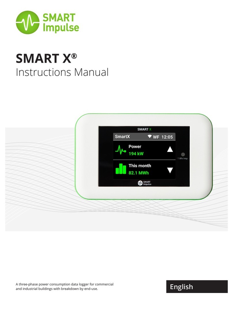
Smart Impulse Smart Analyzer User manual

INSTALLATION MANUAL
Model: Smart Analyzer®
Manufacturer: Smart Impulse
Power meter with consumption breakdown by use
03/12/13

Smart Analyzer® PAGE 2 of 16
Table of contents
Table of contents ........................................................................................................................ 2
1. Introduction ........................................................................................................................ 3
2. Installation precautions ...................................................................................................... 3
2.1. Symbols used on the device and in this manual................................................................. 3
2.2. General installation precautions......................................................................................... 3
2.3. Measurement category....................................................................................................... 3
3. Presentation........................................................................................................................ 4
3.1. Box....................................................................................................................................... 4
4. Installation .......................................................................................................................... 5
4.1. Box set-up ........................................................................................................................... 5
4.2. Sensors set-up ..................................................................................................................... 6
4.3. Connection to the telecommunication network ................................................................ 7
4.4. Connection diagram............................................................................................................ 8
5. Commissioning.................................................................................................................. 10
5.1. Switching on...................................................................................................................... 10
5.2. Configuration .................................................................................................................... 10
6. General features................................................................................................................ 12
6.1. Sizes and weight................................................................................................................ 12
6.2. Power supply..................................................................................................................... 12
6.3. Climatic conditions............................................................................................................ 12
6.4. Compliance with standards............................................................................................... 12
7. Functional features ........................................................................................................... 13
7.1. Reference conditions ........................................................................................................ 13
7.2. Electrical features.............................................................................................................. 13
8. Maintenance ..................................................................................................................... 14

www.smart-impulse.com Smarter Metering
1. Introduction
The Smart Analyzer is a power consumption analyser allowing to breakdown the
consumption by use, with one and only metering device.
In addition to the usual information on quality of the energy, it also provides a percentage
breakdown of the electrical consumption by type of component, equipment or use.
In order to be available, these data will need to be retrieved from the Smart Impulse server,
either in real time thanks to an Internet connection, either at the end of the installation
period, when returning the device to Smart Impulse.
2. Installation precautions
2.1. Symbols used on the device and in this manual
Protective conductor, section 2.5 mm² minimum
WARNING! Danger! Read carefully all the notes designated by this symbol.
2.2. General installation precautions
Read carefully this manual.
The facilities safety in which the Smart Analyzer® is installed remains the
responsibility of these systems’ assemblers.
Improper installation of the device non compliant with this document’s specifications
may compromise the safety of the device as well as other equipments or people
located in its environment.
For your safety, only use the accessories provided with the Smart Analyzer® or
approved by Smart Impulse.
This device can be installed in category III facilities, for voltages not exceeding 300 VAC
isolated from ground (according to the standard EN 60664-1).
2.3. Measurement category
The Smart Analyzer® installation is designed for a Category III 300 V environment.
The measurement category III corresponds to measurements made in the building’s
installation.
Example: measurements on the switchboards, the wiring …

Smart Analyzer® PAGE 4 of 16
3. Presentation
3.1. Box
1) BNC connector to plug the current sensors. From l. to r.: Neutral, phase 1, phase 2,
phase 3.
2) Connector to plug the output Customer Information Port of the electricity network
meters. From l. to r.: drain conductor, I1, I2.
3) Retaining clips on DIN rail.
4) Ground connector, screw M4.
5) Smart Analyzer® power connector. From l. to r.: N.C., Ground, 24 V.
6) Voltage measure connector. From l. to r.: Neutral, Phase 1, Phase 2, Phase 3.
7) USB device and USB Host connectors (x2). For direct connection of USB Storage
devices or remote access keys (Wi-Fi, 3G, …).
8) Ethernet RJ45 connector. For direct connection to wired data processing networks.
9) Light-emitting diodes (LED) indicating the status of the Smart Analyzer®.
1
2
3
4
5
6
8
7
3
9

www.smart-impulse.com Smarter Metering
4. Installation
The Smart Analyzer® installation is made under the responsibility of the electric technician
(Smart Impulse or certified installer).
The latter will need to ensure he has the appropriate training and certifications to deal with
material installations in the Smart Analyser® installation environment, without compromising
its safety, the safety of any person accompanying him or the facilities’ safety on which or next
to which he must work.
The selection of the protection and cut-off devices will be done in accordance with
electrical standards, more specifically regarding the cascading and the selection of the
sizes and breaking capacities.
4.1. Box set-up
The Smart Analyzer® has a DIN rail standardized fastening system.
Please respect the following indications:
1) Set-up a tetrapolar differential circuit breaker with the appropriate breaking
capacities.
2) Implement, downstream from the differential circuit breaker a power supply 230 VAC
towards 24 VDC (500 mA) and its protective circuit breaker with the appropriate
breaking capacities.
3) First connect the ground cable (section 2.5 mm²) to the pin located at the top of the
box to ensure its electric protection (tightening 1.2 N.m).
4) Put the Smart Analyzer® on the DIN rail by engaging first the inferior dogs then turn
the box by retaining the locking tabs.
5) Then, connect the two power wires (ground and 24 V, shielded twisted pair)
Power supply connector

Smart Analyzer® PAGE 6 of 16
4.2. Sensors set-up
Voltage measurement
The voltage measurement is done directly by connecting the Smart Analyzer® to neutral and
to each of the phases with wires of minimum 0.75 mm² section. The phases order is not
important, the Smart Analyzer® will restore it automatically in case of defect.
Down below, you will find the different possible situations.
In order to install the voltage probes, it is recommended to complete the
following steps in this order:
1) Implement the cables routing.
2) Connect the metering wires on the differential circuit breaker.
3) Connect the metering wires on the dedicated terminal block (4
pins).
The neutral must be positioned on the far left. The phase order
may not be respected.
4) Connect the terminal block to the Smart Analyzer®
The voltage metering inputs must be protected in upstream by a differential circuit
breaker 2A 3P+N.
The Smart Analyzer® is not suitable for facilities with IT neutral point connection,
except protection by a control relay of the voltage phase –ground or neutral- ground.
Never manipulate the terminal block (much less the metering wires) when they are in
contact with the potential to measure, in order to prevent any electrocution. In
particular, during the installation, install without fail the terminal block before
switching the metering wires on. On the contrary, when uninstalling, activate the cut-
off system before manipulating the box.

www.smart-impulse.com Smarter Metering
Current measurement
The Smart Analyzer® supports several types of probes such as the “Rogowski coils” type.
The order of phases and sensors direction are not important, the Smart Analyzer® will
restore them automatically in case of defect. Nevertheless, if used, the neutral current
sensor must absolutely be linked to the neutral wire.
To ensure a good installation of the sensors, it is
recommended to complete the following steps:
1) Install the coils around the conductors of the
different phases to measure: open the coil, pass it
around the conductor, and close it making sure it is
well locked.
2) Route the connection cables
3) Connect the BNC plugs and ensure they are well
locked by quarter turn and clockwise.
Note 1: No need to short-circuit the secondary of the
Rogowski coils.
Note 2: if several wires ensure the current’s transit for a
given phase, the current sensor must link all these wires.
Note 3: For a single-phased installation, do not connect
phases 2 and 3.
4.3. Connection to the telecommunication network
The Smart Analyzer® must be connected to the Internet in order to have a continued access
to the processing server.
Local Area Network connection (LAN)
Connect an Ethernet cable of minimum category 5e S/FTP (shielded cable) on the RJ45 plug
located at the bottom of the box. The configuration is automatic in order to allocate an IP
address (by DHCP) and open a virtual private network (VPN) on the port 80.
The Ethernet communication speed of the Smart Analyzer® is 10/100 Mbps.
For any specific configuration or for the Wifi option, check page 10 of this manual.
3G modem connection
If the connection to the company’s LAN isn’t possible, install an Ethernet/3G router. In order
to do that, connect the Smart Analyzer® to the router with an Ethernet cable of minimum
category 5e S/FTP.
The 3G coverage in electrical rooms can be random. A study can be made to position
the radiocommunication antenna correctly.

Smart Analyzer® PAGE 8 of 16
4.4. Connection diagram
Note: this diagram is not valid for IT neutral point connections.

www.smart-impulse.com Smarter Metering

Smart Analyzer® PAGE 10 of 16
5. Commissioning
5.1. Switching on
The device starts automatically as soon as it is supplied with power.
After a start-up time, its proper functioning is indicated by a green light (LED).
The green light-emitting diode is continuous if the Smart Analyzer® has access to the network
and communicates with the Smart Impulse server. The light flashes if the Smart Analyzer®
can’t reach the server. The data are then stored in the local memory, within the limit of the
available space (48 hours approx.).
5.2. Configuration
The device has a web administration interface that enables to set up certain parameters
according to the installation.
Connection:
1) Connect a computer (Windows XP / 7 / 8 or Linux) to the Smart Analyzer via an
Ethernet switch to maintain the Smart Analyzer’s connectivity to the Internet. If the
Smart Analyzer is connected to the client’s LAN which does not allow any other
device to be plugged, do not use a switch.
2) Open a web browser and go on http://<Smart Analyzer’s IP>/index.html. The
following page is displayed :
3) Log in with the password “smartinstall”.

www.smart-impulse.com Smarter Metering
Network configuration
If you have a DHCP network, choose « DHCP » and click on “Confirm”.
If you have fixed IP parameters, choose “Fixed IP”, then click on “Confirm” and fill in the new
proposed fields.
Note: The DNS addresses are optional.
Connectivity test
Test the IP configuration by clicking on the corresponding button. This will send
« ping » requests to google.com to check the Internet network access.
Test the connectivity to Smart Impulse by testing the VPN (Virtual Private Network)
Warning: the message can show “failed” because the VPN is already launched, this is a
normal functioning. The indicated status will then be: “ VPN … : Already running”.
Contact Smart Impulse when these tests are validated in order to check the correct
functioning.
Current sensors association
This configuration is carried out in the factory. Do not modify it except for maintenance
operations.
For each current coil, enter the model and serial number (last line on the RT 2000, code with
bars on the i430 Flex). Click on “Confirm” once these eight information are entered.
Current sensors connection order check
Make sure you connect the blue coil on the neutral (if it is provided). In contrast, the order of
the other coils is detected automatically. This button enables to check the result of this
detection.
Whatever the result, the necessary adjustments are made by the software, no need to
modify the installation.
Learning mode
The learning mode enables to save the parameters of an electrical outlet for a variable
duration (1, 2, 5, 10 or 30 minutes).
In order to do this, enter a name that enables to recognise later the completed measure
(name of the equipment, outlet description…).
Then click on the button to launch the analysis, which will launch a metering process. It is
then possible to uninstall the Smart Analyzer® to go to the next measure or to the
permanent installation.

Smart Analyzer® PAGE 12 of 16
6. General features
6.1. Sizes and weight
212 x 142 x 46 mm
1,0 kg
6.2. Power supply
By external supply module
Operating voltage: 24 V DC
Maximum consumed current: 500 mA
6.3. Climatic conditions
Altitude
Use: 0 … 2000m
Storage: 0 … 10 000m
6.4. Compliance with standards
Electrical safety (according to NF EN 61010-1: 2001)
-Measurement category: III
-Pollution category: 2
-Rated voltage: 300 VRMS
-Indoor use
Electromagnetic compatibility (cat A, non-industrial environment)
-Conducted and radiated emissions according to EN 55011: 2009 / A1: 2010
-Near-field radiated emissions according to EN 62311: 2008
-Immunity to radiated electromagnetic fields according to EN 61000-4-3 / A1: 2008 /
A2: 2011
-Immunity to induced or conducted disturbances according to EN 61000-4-6: 2009
-Immunity to fast transients and bursts according to EN 61000-4-4: 2004 / A1: 2010
-Immunity to electrostatic discharges according to EN 61000-4-2: 2009

www.smart-impulse.com Smarter Metering
7. Functional features
7.1. Reference conditions
Influence quantity
Reference conditions
Room temperature
40°C
Humidity rate
Relative humidity of 45 % to 75 %
Atmospheric pressure
860 to 1060 hPa
Neutral voltage value
230 VRMS ±2 % dc-free
Input voltage of the current circuit
0 VRMS < I < 1 VRMS dc-free
Electrical network frequency
50 ± 0,5 Hz
Phase shifting V / I
0 degree or 90 degrees
Harmonics
< 0,1 %
7.2. Electrical features
Voltage inputs
-Operating range:
Phases - neutral: ≤253 VRMS
-Input impedance: 52 kΩbetween phase and neutral
-Tolerable overload: 275 VRMS in continuous by varistor
Current inputs
-Operating range: 0 –1 V
-Input impedance: 100 Ω
-Tolerable overload: ± 15 V
Features of the device alone (without current sensors)
Influence quantity
Measuring range
Theoretical/ practical
Resolution
Error in the
reference range
Minimum
Maximum
Voltage
0 V
715 Vdc
10 mV / 100 mV
0.1 %
Density
Values depending on
the used current
sensors
Typ. 16 kARMS
and 3.7 MVA max.
Typ. 1 A or less
0.1 % + sensor
Active powers
Typ. 200 W or less
0.1 % + sensor
Reactive powers
Typ. 200 VAR or less
0.1 % + sensor
Apparent powers
Typ. 200 VA or less
0,1 % + sensor
Power factors
0
1
0.01 / 0.01
0.1 %

Smart Analyzer® PAGE 14 of 16
Nominal operating range
Frequency: 40 to 70 Hz
Harmonics: THD(I): 0 to 40 %
THD(U): 0 to 20 %
Magnetic field: 0 to 400 A/m
Electrical field: 0 to 3 V/m
Relative humidity: 10 to 90 %, without condensation.
8. Maintenance
No cleaning is required for the proper operation of the device. If necessary, use a dry cloth.
For any maintenance operation, contact Smart Impulse. The company will deal with the
necessary operations:
Smart Impulse
48 rue René Clair
75018 PARIS
FRANCE
+33(0)1 84 17 31 25
technique@smart-impulse.com

www.smart-impulse.com Smarter Metering
Notes

Smart Analyzer® PAGE 16 of 16
SMART IMPULSE
48 rue René Clair
75018 PARIS
+33(0)1 84 17 31 20 –contact@smart-impulse.com
Table of contents
Other Smart Impulse Measuring Instrument manuals
Popular Measuring Instrument manuals by other brands
Dranetz
Dranetz Energy Platform user guide
Verathon
Verathon BladderScan BVI 3000 Operator's manual

Agilent Technologies
Agilent Technologies 86140B Series user guide
Oval
Oval FLOWPET-EG LS5277-4 0B Series instructions

Somogyi Elektronic
Somogyi Elektronic home VC 830L instruction manual
Bender
Bender ISOMETER isoRW425 quick start guide
