SMART MATERIAL EEL1500-1 User manual

VERSION 1.0 JULY 2021
EEL1500-1
User Manual
Version 1.0
Electrical Engineering Ltd.

Page2 https://www.smart-material.com
EEL1500-1 User Manual V1.0
Contents
1. Safety Instructions AND Symbols
READ First ................................................................. Page3
2. Overview................................................................... Page5
2.1 FRONT PANEL. . . . . . . . . . . . . . . . . . . . . Page6
2.2 Rear panel . . . . . . . . . . . . . . . . . . . . . Page8
3. Inspection AND PARTS................................................. Page9
3.1 What comes with the EEL1500-1 . . . . . . . . . . Page9
3.2 Inspection and Verification of the EEL1500-1 . . Page9
4. SPecifications......................................................... Page10
4.1 General Specifications . . . . . . . . . . . . . Page10
4.2 Output voltage, current, power. . . . . . . . . Page10
4.3 Monitor outputs . . . . . . . . . . . . . . . . . Page11
5. Operations .............................................................. Page12
6. TroublEshooting ..................................................... Page13
7. Further Resources .................................................. Page14
© Electrical Energy Limited, LLC and Smart Material Corp.
All rights reserved. No part of this manual may be reproduced without the prior permission of Smart Material Corporation.
This document is for the instructional use of the EEL1500-1. Please read carefully before using the equipment.

Page3 https://www.smart-material.com
EEL1500-1 User Manual V1.0
To ensure safe operation and to keep the operator and the product safe,
THE INFORMATION, CAUTIONS, AND WARNINGS IN THIS
MANUAL MUST BE HEEDED.
WARNING – WARNING STATEMENTS AND SYMBOLS IDENTIFY
CONDITIONS OR PRACTICES THAT COULD RESULT IN INJURY OR
LOSS OF LIFE.
CAUTION – CAUTION STATEMENTS AND SYMBOLS IDENTIFY
CONDITIONS OR PRACTICES THAT COULD RESULT IN DAMAGE TO
THIS PRODUCT OR OTHER PROPERTY.
REVIEW THE FOLLOWING SAFETY PRECAUTIONS TO AVOID INJURY AND
PREVENT DAMAGE TO THIS PRODUCT OR ANY PRODUCTS CONNECTED
TO IT. TO AVOID POTENTIAL HAZARD, USE THIS PRODUCT ONLY AS
SPECIFIED.
• Only qualied personnel should operate and make connections to this
unit.
• All connections including removal of any connections from the High
Voltage Output Connector must be done with the unit OFF and discon-
nected from the AC line source.
• To avoid shock hazard, electrocution, or re, observe all ratings and
markings on the product. Consult the User’s Manual for further safety
information before making connections to the product.
Make sure that attached cables are electrically and mechanically NOT
defective. Replace cables only with the high voltage amplier switched o.
Before removing the cables from the load, switch o the amplier and wait
at least 5 minutes until the load capacitors are discharged.
1. Safety Instructions AND Symbols
READ First

Page4 https://www.smart-material.com
EEL1500-1 User Manual V1.0
Warning!
HAZARDOUS VOLTAGES UP TO 2000V ARE
PRESENT AT THE OUTPUT OF THE HIGH VOLTAGE
AMPLIFIER.
TAKE APPROPRIATE PRECAUTIONS DURING
MEASUREMENT PROCEDURES.
BEFORE TURNING ON THE AMPLIFIER, REMOVE
HANDS AND ALL TEST EQUIPMENT FROM THE
LOAD AND CONNECTED CABLES!!

Page5 https://www.smart-material.com
EEL1500-1 User Manual V1.0
The High Voltage Amplier (HVA) model EEL1500-1 is specically designed
for the MacroFiberComposite™ (MFC).
The EEL1500-1 is a compact, high speed, 55 Watt High Voltage Amplier
capable of generating a -500 to +1500Vpp output @ +/-50mA with a large
signal bandwidth greater than 150kHz at -3db no load.
There are three LED indicators on the front panel signaling the following
conditions:
1. When the unit is powered on, the LED POWER ON illuminates,
2. When the high voltage is on (enabled), the LED HIGH VOLTAGE
illuminates,
3. If high voltage output goes into an Out-Of-Regulation condition (high
voltage output doesn’t match the input), the LED OUT OF REGULATION
illuminates.
The high voltage is turned ON by providing a TTL LOW to the HIGH
VOLTAGE ENABLE BNC on the rear panel, or by plugging the shorting cap to
the HIGH VOLTAGE ENABLE BNC.
A DYNAMIC ADJUSTMENT1 turn potentiometer is provided on the front
panel to adjust for optimum square wave shape with varying capacitive
loads.
Two monitors are provided. The VOLTAGE MONITOR BNC represents
a 1:200 representation of the HIGH VOLTAGE OUTPUT. The CURRENT
MONITOR BNC represents a 1V to 5mA representation of the CURRENT
being drawn from the amplier.
2. Overview
Page6 https://www.smart-material.com
EEL1500-1 User Manual V1.0
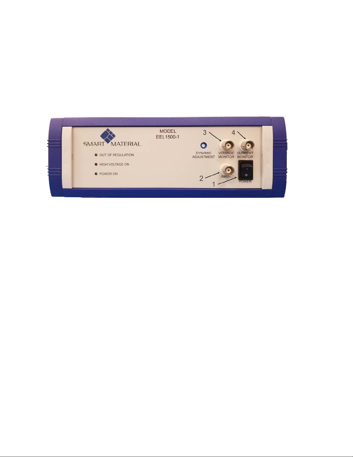
2.1 FRONT PANEL
The Front Panel of the Model EEL1100.50.1 is shown in Figure 2-1 and 2.2.
The information provides important details on features provided, which will
be useful for operating the product to its fullest capability.
Fig. 2-1 EEL1500-1 Front Panel
1. POWER SWITCH
Rocker switch to turn ON and OFF the AC source to the unit.
2. INPUT
BNC used for connecting DC or AC sources to be amplied.
3. VOLTAGE MONITOR
BNC used for monitoring a 200:1 replica of the HV OUTPUT.
4. CURRENT MONITOR
BNC used for monitoring the value of current being drawn from the
unit at a 1V/5mA ratio.

Page7 https://www.smart-material.com
EEL1500-1 User Manual V1.0
Fig. 2-2 EEL1500-1 Front Panel
5. DYNAMIC ADJUSTMENT
A one Turn Potentiometer used to adjust for best square wave
performance with various capacitive load.
6. OUT OF REGULATION
Amber LED illuminated indicates when the HIGH VOLTAGE OUTPUT
doesn’t conform to the proper value as dictated by the INPUT
signal.
7. HIGH VOLTAGE ON
Red LED Illuminated indicates the HIGH VOLTAGE OUTPUT is ON
(Enabled)
8. POWER ON
Green LED illuminated indicates the unit is powered ON

Page8 https://www.smart-material.com
EEL1500-1 User Manual V1.0
2.2 Rear panel
The Rear Panel of the Model EEL1500-1 is shown in Figure 2-3. The
information provides important details on the features provided, which will
be useful for operating the product to its fullest capability.
Fig. 2-3 EEL1500-1 Rear Panel
1. AC POWER PLUG
Standard AC plug with internal fuse holder.
2. HIGH VOLTAGE OUTPUT
SHV connector used to connect the unit to the high side of load.
3. GROUND LUG
8 – 32 Threaded Lug used for a ground return from the load.
4. HIGH VOLTAGE ENABLE
BNC connector to accept a TTL Low signal to Enable High Voltage or
a TTL High signal (or open) will Disable High Voltage.
5. SHORTING CAP
Used to Enable High Voltage if external TTL Signals are not used.

Page9 https://www.smart-material.com
EEL1500-1 User Manual V1.0
3.1 What comes with the EEL1500-1
The EEL1500-1 package contains the following items:
1. The EEL1500-1
2. Power cord.
3. User’s Manual.
4. High Voltage Output SHV plug and cable, unterminated.
3.2 Inspection and Verification of the EEL1500-1
Remove the unit from the packaging and verify that no damage occurred to
the product during shipping.
1. If any damage is observed, contact customer service before proceeding
any further.
2. Make sure the front panel POWER switch is in the OFF position (O).
3. Remove the shorting cap from the HIGH VOLTAGE ENABLE BNC on
the rear panel.
4. Connect a DMM to VOLTAGE MONITOR BNC set for DCV.
5. Connect a 1VDC source to INPUT BNC.
6. Plug the unit into a 85 - 264VAC line source.
7. Turn the POWER switch on the front panel to ON (I). The fan should
be ON and the DMM should read 0V.
8. Plug the shorting cap into the HIGH VOLTAGE ENABLE BNC on the
rear panel and the DMM should read 1.0VDC.
9. Change the 1.0VDC source to -1.0VDC and verify the DMM reads
-1.0VDC.
10. Remove the shorting cap from the HIGH VOLTAGE ENABLE BNC and
verify the DMM reads 0VDC.
11. Turn the POWER switch OFF(O). This completes the unit verication
testing.
3. Inspection AND PARTS
Page10 https://www.smart-material.com
EEL1500-1 User Manual V1.0
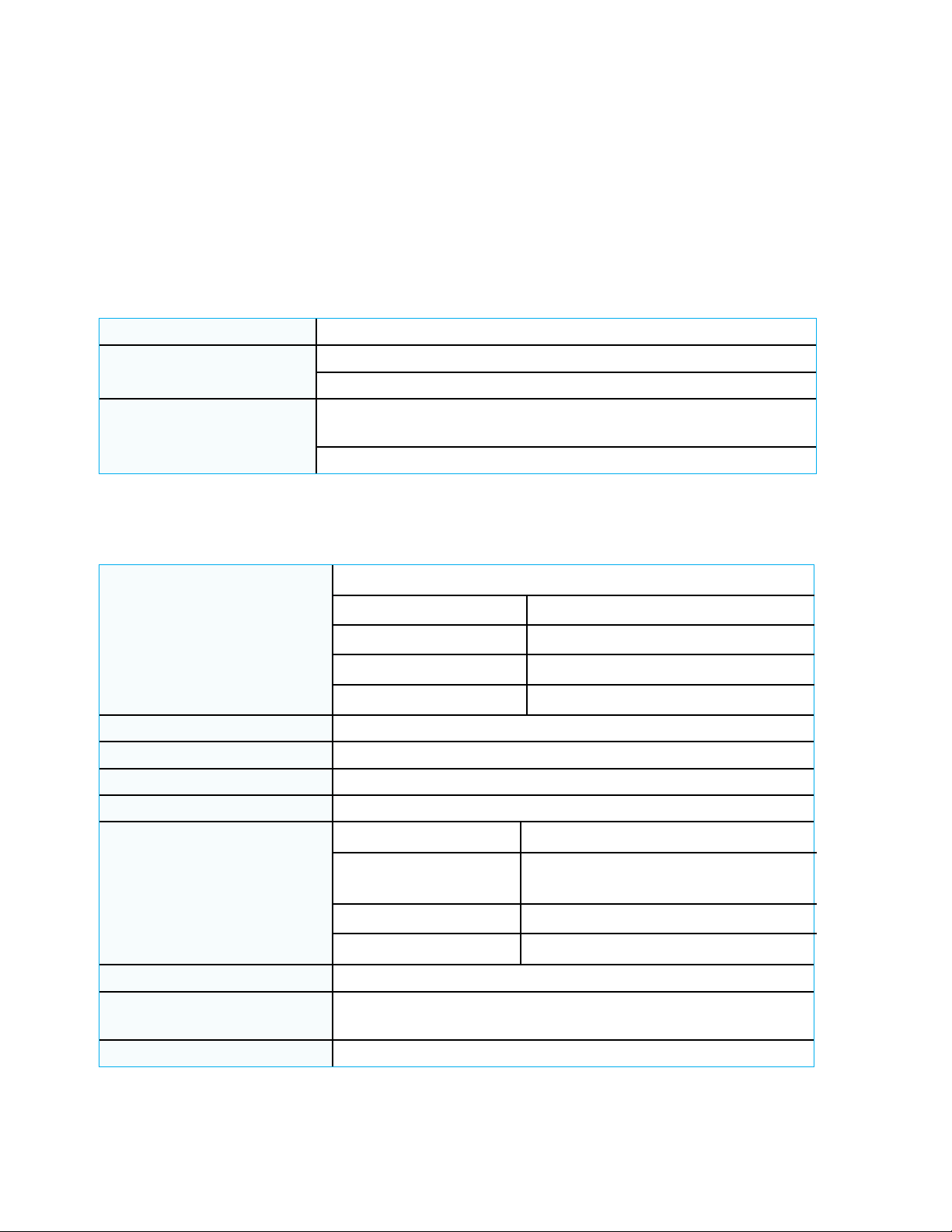
4.1 General Specifications
The EEL1500-1 is designed to be operated as a high voltage power supply
for the MacroFiberComposite™, MFC P1 type products.
Main Power supply 100 - 240VAC, 50 - 60Hz
Operating Conditions Ambient Temperature 5°C to 40°C
Relative Humidity up to 75%, noncondensing
Mechanical
85mm (3.34”) H X 250mm (9.84”) W X 260mm
(10.23”) D
Weight approx. 2kg (4.5lbs)
4.2 Output voltage, current, power
High Voltage Output
-500V DC to +1500V DC or peak AC
Accuracy: 0.5% of F.S.
Noise: <600mVrms
Oset: <1V DC
Output Connector: SHV coax
Current ±50mA
Power Rating 55W
Large Signal Bandwidth >150kHz No load -3db
Small Signal Bandwidth >165kHz No load -3db
Input HV Control
Input Gain: 200
Input Voltage
Range:
-2.5V to +7.5V
(for output -500V to +1500V)
Input Impedance 50kOhm
Input Connector: BNC
High Voltage Enable TTL, Open Collector
High Voltage Enable
Connector BNC with shorting plug
Dynamic Adjustment One turn potentiometer
4. SPecifications

Page11 https://www.smart-material.com
EEL1500-1 User Manual V1.0
4.3 Monitor outputs
Voltage Monitor
Output Voltage: 200:1 (1V = 200V)
Accuracy: 0.1% of Full Scale
Bandwidth: 200kHz
Min. Output Impedance: > 1kOhm
Output Connector: BNC
Current Monitor
Output Voltage: 1V = 5mA
Accuracy: 1% of Full Scale
Bandwidth: 10kHz
Min. Output Impedance: > 1kOhm
Output Connector: BNC

Page12 https://www.smart-material.com
EEL1500-1 User Manual V1.0
The Model EEL1500-1 amplies a signal that is applied to the INPUT BNC
with a gain ratio of 200:1.
WARNING – HIGH VOLTAGE CAN BE PRESENT AT THE
HIGH VOLTAGE OUTPUT WHEN THE UNIT IS TURNED ON.
DO NOT MAKE ANY CONNECTIONS TO THE HIGH VOLTAGE
OUTPUT WHILE THE UNIT IS ON OR PLUGGED INTO AN AC
SOURCE. ALL CONNECTIONS TO THE LOAD MUST BE DONE
WITH THE UNIT OFF AND UNPLUGGED.
1. Make sure the front panel POWER switch is in the OFF position (O)
and the unit is not plugged into an AC source.
2. Remove the shorting cap from the HIGH VOLTAGE ENABLE BNC on
the rear panel.
3. Connect a DMM or an Oscilloscope to VOLTAGE MONITOR BNC set for
DCV.
4. Connect a -2.5V to +7.5VDC source (set to 0VDC) to the INPUT BNC.
5. Plug the unit into an 85 - 264VAC line source.
6. Turn the POWER switch on the front panel to ON (I). The fan should
be ON and the DMM/Oscilloscope should read 0V.
7. Plug the shorting cap into the HIGH VOLTAGE ENABLE BNC on the rear
panel, the DMM/Oscilloscope should still read 0VDC at the VOLTAGE
MONITOR BNC.
8. Change the INPUT source to -2.5VDC and verify the DMM/Oscilloscope
reads -2.5VDC.
9. Change the INPUT source to +7.5VDC and verify the DMM/Oscilloscope
reads +7.5VDC
10. Remove the shorting cap from the HIGH VOLTAGE ENABLE BNC on
the rear panel and verify the DMM/Oscilloscope at the VOLTAGE
MONITOR reads 0V.
11. Turn the POWER switch o (O). This completes the unit verication
testing.
5. Operations

Page13 https://www.smart-material.com
EEL1500-1 User Manual V1.0
Symptom Check Action
Does not power up
Verify unit is plugged
into an active AC source
(85 – 264VAC)
Plug the unit into an
active AC source (85 –
264VAC)
Verify fuse is installed
in the AC Plug module
on the Rear Panel
Install 2.5A Slow Blow
Fuse (5mm x 20mm)
Verify fuse is not open
(tripped)
Contact customer
support @ Smart
Material
No HIGH VOLTAGE
output
Verify High Voltage
cable is plugged into
the HIGH VOLTAGE
OUTPUT CONNECTOR
on the Rear Panel
Plug High Voltage Cable
into the HIGH VOLTAGE
OUTPUT CONNECTOR
on the Rear Panel
Verify the EEL1500-1
is switched ON and the
Power LED on the front
panel illuminates
Switch the unit on
Verify the shorting cap
on the Rear Panel is
plugged in and the High
Voltage LED on the
front panel illuminates
Plug the shorting cap
into the HIGH VOLTAGE
ENABLE plug on the
rear panel
Unit is ON, but the fan
is not running
Contact customer
support @ Smart
Material
6. TroublEshooting

Page14 https://www.smart-material.com
EEL1500-1 User Manual V1.0
7. Further Resources
Follow our popular in-depth tutorials on on our YouTube
channel SmartMaterialCorp.
Contacts:
e-mail: support@smart-material.com
Smart Material Corp.
2170 Main Street, Suite 302
Sarasota, FL 34237
U.S.A.
Toll Free: 888 385 8955
Tel: +1 941 870 3337
Fax: +1 941 296 7015
Smart Material GmbH
Löbtauer Str. 69
01159 Dresden
Germany
Tel: +49 351 4977 145
Fax: +49 351 4977 146

Page15 https://www.smart-material.com
EEL1500-1 User Manual V1.0
1. Limited Warranty
(a) Seller warrants to the Buyer that, for a period of eighteen (18) months from the date of delivery of
the Product(s) by Seller to a commercial carrier, the Product(s) will conform to Seller’s stated specications and be
free from defects in workmanship and materials.
(b) Seller’s limited warranty set forth in Section 1(a) shall not apply to any Product components that
experience normal wear and tear.
(c) In order to maintain the limited warranty set forth in Section 1(a), Buyer must have the Product(s)
calibrated on an annual basis.
(d) IN THE EVENT OF ANY BREACH OF THE LIMITED WARRANTY SET FORTH IN SECTION 1(a), SELLER’S
SOLE OBLIGATION SHALL BE EXCLUSIVELY LIMITED TO, AT THE SOLE OPTION OF SELLER: (i) REPAIR OR
REPLACEMENT, FCA SELLER’S DELIVERY POINT, OF ANY PRODUCT THAT SELLER DETERMINES TO BE DEFECTIVE;
OR (ii) A FULL REFUND OF THE PURCHASE PRICE UPON RETURN OF THE PRODUCT(S) TO SELLER, WITH BUYER
RESPONSIBLE FOR PACKAGING AND SHIPPING THE PRODUCT(S) TO SELLER.
(e) SELLER’S MAXIMUM LIABILITY TO BUYER WITH RESPECT TO THE PRODUCT(S) SHALL IN NO EVENT
EXCEED THE PURCHASE PRICE PAID BY BUYER FOR THE PRODUCT(S) THAT ARE THE SUBJECT OF THE
APPLICABLE CLAIM.
(f) EXCEPT FOR THE LIMITED WARRANTY SET FORTH IN THIS SECTION, SELLER MAKES NO OTHER
WARRANTIES WITH RESPECT TO ANY PRODUCT(S), WHETHER EXPRESSED OR IMPLIED, INCLUDING ANY
WARRANTIES OF MERCHANTABILITY, FITNESS FOR A PARTICULAR PURPOSE, QUALITY AND/OR THOSE ARISING
BY STATUTE OR OTHERWISE BY LAW OR FROM ANY COURSE OF DEALING OR USE OF TRADE, ALL OF WHICH ARE
HEREBY EXPRESSLY DISCLAIMED. SELLER DOES NOT WARRANT OR GUARANTY THAT BUYER WILL REALIZE ANY
RESULTS BY VIRTUE OF THE USE OF THE PRODUCT(S).
(g) ANY ORAL OR WRITTEN STATEMENT, INFORMATION OR ADVICE GIVEN OR MADE BY SELLER OR
ANY OF ITS EMPLOYEES, AGENTS, REPRESENTATIVES OR DISTRIBUTORS ABOUT THE PRODUCT(S) OR THE
PERFORMANCE OF THE PRODUCT(S): (i) SHALL NOT CONSTITUTE A SELLER REPRESENTATION OR WARRANTY
OR IN ANY WAY INCREASE THE SCOPE OF THE LIMITED WARRANTY SET FORTH IN SECTION(a); (ii) SHALL
NOT BE RELIED UPON BY BUYER OR ANY OTHER PERSON AND BUYER ACKNOWLEDGES THAT SUCH WAS NOT
RELIED UPON BY BUYER IN DECIDING TO PURCHASE THE PRODUCT; AND (iii) IS NOT A PART OF THE LIMITED
WARRANTY SET FORTH IN SECTION(a).
(h) Seller shall not be liable for a breach of the limited warranty set forth in Section(a) unless: (i) Buyer
delivers written notice of the defective Product(s) to Seller within eighteen (18) months from the date of delivery
of the Product(s) by Seller to the commercial carrier; (ii) Seller is allowed a reasonable opportunity after receiving
the written notice to examine such Products; and (iii) Seller reasonably veries Buyer’s claim that the Products
are defective. Seller shall not be liable for a breach of the limited warranty set forth in Section(a) if: (i) Buyer
makes any further use of such Products after delivering written notice; (ii) the defect arose because Buyer
improperly used and/or inadequately maintained the Product(s); or (iii) Buyer alters or repairs such Product(s)
without the prior written consent of Seller.
(j) THE REMEDIES SET FORTH IN THIS SECTION SHALL BE THE BUYER’S SOLE AND EXCLUSIVE REMEDY AND
THE SELLER’S ENTIRE LIABILITY FOR ANY BREACH OF THE LIMITED WARRANTY SET FORTH IN SECTION 1(a).
2. Indemnication.
Buyer agrees to defend, indemnify and hold harmless Seller and each of its aliates and each of their respective
directors, ocers, managers, members, employees, agents, successors and assigns (collectively, “Indemnied
Parties”) against any damage, loss, liability, cost or expense (including reasonable attorneys’ fees) incurred by any
Indemnied Party arising out of or resulting from any third party claim arising out of or relating to any products
sold by Buyer that incorporate the Product(s).

Page16 https://www.smart-material.com
EEL1500-1 User Manual V1.0
3. Limitation of Liability.
(a) IN NO EVENT SHALL SELLER BE LIABLE TO BUYER OR TO ANY THIRD PARTY, WHETHER IN CONTRACT,
NEGLIGENCE, TORT OR UNDER ANY OTHER THEORY OF LAW, FOR LOSS OF PROFITS, LOSS OF BUSINESS OR
LOSS OF BUSINESS OPPORTUNITY, OR FOR ANY INCIDENTAL, CONSEQUENTIAL, SPECIAL, EXEMPLARY, PUNITIVE
OR INDIRECT DAMAGES, HOWSOEVER CAUSED AND WHETHER FORESEEABLE OR NOT.
(b) The limitation of liability set forth in this Section 6 shall apply to the maximum extent permitted by law.
4. Miscellaneous.
Governing Law; Jurisdiction/Venue. These Terms shall be governed by, and construed in accordance with, the
laws of the State of Florida, U.S.A. if the unit is sold by Smart Material Corp., the laws of Germany if the unit is
sold by Smart Material GmbH without reference to conicts of law principles. For purposes of litigating any claim
or dispute arising from or related to this Agreement, the parties irrevocably submit and consent to the exclusive
jurisdiction and venue of the State of Florida courts located in Sarasota County, Florida, or exclusive jurisdiction
and venue of the courts located at Dresden, Germany.
© Electrical Energy Limited, LLC and Smart Material Corp.
All rights reserved. No part of this manual may be reproduced without the prior permission of Smart Material Corporation.
This document is for the instructional use of the EEL1500-1. Please read carefully before using the equipment.
Table of contents
Other SMART MATERIAL Amplifier manuals


