Smart Storm USM UV254 User manual


UNIVERSAL SMART METER COD METER USER MANUAL v2.0.docx page 2 of 50
Contents
1. Specification. .......................................................................................................5
2. General Information.............................................................................................6
2.1. Safety information.........................................................................................6
2.2. Use of hazard information.............................................................................7
2.3. Precautionary labels......................................................................................7
2.4. Wiring and Handling Precautions..................................................................8
3. Turning ON the Environmental USM. ..................................................................9
3.1. UV254 Probes...............................................................................................9
3.1.1. Digital Probes.........................................................................................9
3.2. USM Connections.........................................................................................9
3.3. Turn On.......................................................................................................12
4. Configuring the USM. ........................................................................................13
4.1. Configuration menu access.........................................................................14
4.2. Configuration Menu.....................................................................................15
4.3. Digital Probe SET UP for UV254.................................................................16
4.3.1. Detect Probe.........................................................................................16
4.3.2. Display Parameters. .............................................................................17
4.3.1. What is COD?.......................................................................................18
4.3.2. COD Calibration. ..................................................................................19
4.3.3. Digital Probe Calibration.......................................................................22
4.3.3.1. TSS................................................................................................22
4.3.3.2. Gain factor correction.....................................................................22
...........................................................................................................................23
4.4. Message SET UP........................................................................................24
4.5. Modbus BMS SET UP.................................................................................25
4.6. 4-20mA SET UP..........................................................................................26
4.6.1. Typical 4-20mA SET UP for UV254 Balancing.....................................28
4.7. 4-20mA Test................................................................................................29
4.8. Relay Set up................................................................................................31
4.9. Relay Cleaning Cycle:.................................................................................33
4.10. Relay Test................................................................................................33
4.11. New User Password. ...............................................................................34

UNIVERSAL SMART METER COD METER USER MANUAL v2.0.docx page 3 of 50
4.12. Set Date and Time...................................................................................34
4.13. Screen Save Mode. .................................................................................34
4.14. Logger Interval.........................................................................................35
4.15. Engineer Menu.........................................................................................36
4.16. WHAT IS UVA AND UVT?.......................................................................37
5. Pathlength and UVA/UVT..................................................................................37
5.1. UVA CALIBRATION....................................................................................38
5.1.1. UVA CALIBRATION SET UP. ..............................................................38
6. USM Display Screens........................................................................................39
6.1. HOME SCREEN. ........................................................................................40
6.2. Digital Probe Screen 1................................................................................42
6.3. Digital Probe Screen 2................................................................................42
6.4. Relay Status Screens..................................................................................44
6.5. 4-20mA Screens. ........................................................................................45
6.6. Slope Configuration Screen. .......................................................................45
6.7. Date and Time Screen................................................................................46
6.8. Modbus Set Up Screen...............................................................................46
6.9. About USM..................................................................................................46
6.10. UV254 Range ..........................................................................................46
7. Fault Finding......................................................................................................47
8. Appendices........................................................................................................48
8.1. APPENDIX A. ISE PROBES.......................................................................48
8.2. APPENDIX B. Modbus Registers...............................................................49
9. Declaration of Conformity ..................................................................................50
List of Tables
Table 1-1 Device Specification..............................................................................................5
Table 4-1 Key Functionality.................................................................................................13
Table 4-2 Digital Probe Parameters....................................................................................17
Table 6-1 UV254 Probe Range........................................................................................47
Table 6-2 Accurancy Reading Range..................................................................................47
Table 6-3 Fault Finding.......................................................................................................47
Table 7-1ModBus Registers................................................................................................49

UNIVERSAL SMART METER COD METER USER MANUAL v2.0.docx page 4 of 50
List of Figures
Figure 3-1 Relay Board Connections .......................................................................11
Figure 3-2 Smart Storm Screen ...............................................................................12
Figure 3-3 Home Screen..........................................................................................12
Figure 4-1 USM........................................................................................................13
Figure 4-2 Password Screen....................................................................................14
Figure 4-3 Configuration Menu Screen ....................................................................14
Figure 4-22 Digital Probe Detect..............................................................................16
Figure 4-23 Digital Probe Scan Result.....................................................................16
Figure 4-24 Display Digital Probe Parameters.........................................................17
Figure 4-25 Temperature Mode ...............................................................................25
Figure 4-26 MODBUS Setup....................................................................................25
Figure 4-27 MODBUS Parameter Select..................................................................26
Figure 4-28 4-20mA Status Screen..........................................................................27
Figure 4-29 4-20mA Set UP Screen.........................................................................27
Figure 4-30 4-20mA Parameter Selection................................................................28
Figure 4-31 4-20mA for UV balancing......................................................................28
Figure 4-32 4-20mA Testing.....................................................................................29
Figure 4-33 Change the mA Output.........................................................................30
Figure 4-34 Relay Status Screen. ............................................................................31
Figure 4-35 Relay Set Up Screen. ...........................................................................31
Figure 4-36 Relay Set Up Parameter Change..........................................................32
Figure 4-37 Relay Testing........................................................................................33
Figure 4-38 Time and Date Setting..........................................................................34
Figure 4-39 Screen Saver Setting............................................................................34
Figure 4-40 Logger Interval Setting..........................................................................35
Figure 4-41 Password……………..………………….…………………..…….…………35
Figure 4-42 Engineering MENU.………………………….……..…………………….…35
Figure 4-43 Logger Interval Setting………………………………………………………40
Figure 4-44 Calibrate UVA ……….………………………………………………………40
Figure 4-45 Sampling Screen…….………………………………………………………41
Figure 5-1 Home Screen UV ...................................................................................40
Figure 5-2 Home Screen UV254 with Temperature.................................................40
Figure 5-3 Digital Probe Only...................................................................................40
Figure 5-4 Digital Probe Screen 1............................................................................42
Figure 5-5 Digital Probe Screen 2............................................................................42
Figure 5-6 Digital Probe Screen 3............................................................................42
Figure 5-6 Relay Page 1. .........................................................................................44
Figure 5-7 Relay Page 2. .........................................................................................44
Figure 5-8 4-20mA Screen.......................................................................................45
Figure 5-9 Slope Configuration. ...............................................................................45
Figure 5-10 Modbus Set Up Screen.........................................................................46

UNIVERSAL SMART METER COD METER USER MANUAL v2.0.docx page 5 of 50
1. Specification.
Specifications
Universal Smart Meter –level Meter
Inputs
Temperature Range
Display
Relays
Current Output
Mains Supply
DC Supply
Power Consumption
Weight
Enclosure Dimensions
Mounting Dimensions (including cable
glands, etc.)
UV254 probe.
-5 - 50 °C
Graphic LCD 124x64 dots Negative
Blue
3 SPDT, 5A
4 –20 mA galvanic isolated
100 –240 VAC 50/60Hz. Switched-
mode power supply
12V or 24V
5VA
450 grams, Wall Mount Version
160 mm x 130 mm x 60 mm
185 mm x 155 mm x 60 mm
Table 1-1 Device Specification

UNIVERSAL SMART METER COD METER USER MANUAL v2.0.docx page 6 of 50
2. General Information.
The information contained in this manual has been carefully checked and is believed
to be accurate. However, Smart Storm assumes no responsibility for any inaccuracies
that may be contained in this manual. In no event will the Smart Storm be liable for
direct, indirect, special, incidental, or consequential damages resulting fromanydefect
or omission in this manual, even if advised of the possibility of such damages. In the
interest of continued product development, Smart Storm reserves the right to make
improvements in this manual and the products it describes at any time, without notice
or obligation. Revised editions may be found on the Smart Storm’s web site
www.smartstormgroup.com.
2.1. Safety information
Please read this entire manual before unpacking, setting up or operating this
equipment. Pay attention to all danger, warning and caution statements. Failure
to do so could result in serious injury to the operator or damage to the
equipment. Make sure that the protection provided by this equipment is not
impaired, do not use or install this equipment in any manner other than that
specified in this manual.
DANGER
Smart Storm products are designed for outdoor use are provided with a high level of ingress
protection against liquids and dust (see specification for rating). If these products are connected to
a mains electricity socket by means of a cable and plug rather than by fixed wiring, the level of
ingress protection of the plug and socket connection against liquids and dust is considerably lower.
It is the responsibility of the operator to protect the plug and socket connection in such a manner
that the connection has an adequate level of ingress protection against liquids and dust and
complies with the local safety regulations. When the instrument is used outdoors, it should be
connected only to a suitable socket with at least IP44 rating (protection against water sprayed from
all directions).

UNIVERSAL SMART METER COD METER USER MANUAL v2.0.docx page 7 of 50
2.2. Use of hazard information
DANGER
Indicates a potentially or imminently hazardous situation which, if not avoided, could result in
death or serious injury.
WARNING
Indicates a potentially or imminently hazardous situation which, if not avoided, could result in
death or serious injury.
CAUTION
Indicates a potentially hazardous situation that may result in minor or moderate injury.
NOTICE
Indicates a situation that, if not avoided, could result in damage to the instrument. It also indicates
information that requires special notice.
2.3. Precautionary labels
Read all labels and tags attached to the instrument. Personal injury or damage
to the instrument could occur if not fully observed.
This symbol, if noted on the instrument, references the
instruction manual for operation and/or safety information.
This symbol, when noted on a product enclosure or barrier,
indicates that a risk of electrical shock and/or electrocution
exists.
This symbol, if noted on the product, indicates the need for
protective eye wear.
This symbol, when noted on the product, identifies the location
of the connection for Protective Earth (ground).
This symbol, when noted on the product, identifies the location
of a fuse or current limiting device.

UNIVERSAL SMART METER COD METER USER MANUAL v2.0.docx page 8 of 50
2.4. Wiring and Handling Precautions
DANGER
Electrocution Hazard. Always disconnect mains supply before removing covers and
connecting any external wiring.
Only qualified Electricians should install this product. IET BS7671:2008 wiring regulations
must be adhered to when installing the product.
NOTICE
Delicate internal electronic components can be damaged by static electricity, resulting in
indeterminate instrument performance or eventual failure. Smart Storm recommends
taking the following steps to prevent ESD damage to your instrument:
•Before touching any instrument electronic components (such as printed circuit
cards and the components on them) discharge static electricity from your body.
The user can accomplish this by touching an earth - grounded metal surface for 3
seconds such as the chassis of an instrument, or a metal conduit or pipe.
•To reduce static build-up, avoid excessive movement. Transport static-sensitive
components in anti-static containers or packaging.
•To discharge static electricity from your body and keep it discharged, wear a wrist
strap connected by a wire to earth ground, especially when handling circuit
boards.
•Handle all static - sensitive components in a static - safe area. If possible, use anti-
static floor pads and work bench pads.
DANGER
Electrocution hazard. Always install a ground fault interrupt circuit (GFIC)/ residual
current circuit breaker (RCCB) with a maximum trigger current of 30 mA. If installed
outside, provide overvoltage protection through an MCB rated not greater than 5 Amps.
DANGER
With fixed wiring, a disconnecting device (local interruption) must be integrated into the
power supply line. The disconnecting device must meet BS7671:2008 standards and
regulations. It must be installed near the device, be able to be reached easily by the
operator and labelled as a disconnecting device.
If the connection is established using a mains connection cable that is permanently
connected to the power supply, the plug of the mains connection cable can serve as local
interruption.
DANGER
Ensure the relays are not subjected to loads great than 5 Amps as this will cause internal
damage and possible product destruction.

UNIVERSAL SMART METER COD METER USER MANUAL v2.0.docx page 9 of 50
3. Turning ON the Environmental USM.
The instrument is designed to read a range of environmental measurements
associated with the wastewater industry with an optional on-board data logger for
recording and downloading to the Smart Storm Inquisitor data viewing platform.
Three relays (with LED indication) and two 4-20mA outputs are provided to control
ancillary equipment and the meter can be interrogated remotely using Modbus RTU
(RS485) communication.
3.1. UV254 Probes.
The USM can be used with one ISE probe AND one digital probe from the
following lists.
3.1.1.Digital Probes.
The following Digital probes can be used with the USM:
•UV254
•TSS
3.2. USM Connections.
The connection terminals are accessible by removing the cover of the USM. All
connections should be made through appropriate cable glands to maintain the
IP rating of the unit as shown on figure 3-1.
➢The unit is factory built to either 100 –240 Vac input (CONN2) or DC
input (CONN3).
➢CONN4 provides access to three configurable relays with Common
(COM), Normally Open (NO) and Normally Closed (NC) connections
available.
➢CONN5 provides two isolated 4-20mA outputs.
➢CONN6 - top row provides the RS485 connections for remote access to
the USM measurements (Building Management System BMS).

UNIVERSAL SMART METER COD METER USER MANUAL v2.0.docx page 10 of 50
➢CONN6 - bottom row provides the RS485 connections for the connection
of a digital probe. The power connections for the probes are also
available.
➢CONN7 –provides the connection for the ISE probe including a PT100
temperature input and a connection for grounded probes.

UNIVERSAL SMART METER COD METER USER MANUAL v2.0.docx page 11 of 50
Figure 3-1 PCB Board Connections
UNIVERSAL SMART METER COD METER USER MANUAL v2.0.docx page 12 of 50
3.3. Turn On.
When the unit is turned on a splash screen (Figure 1) will be shown detailing
the contact details of Smart Storm.
Figure 3-2 Smart Storm Screen
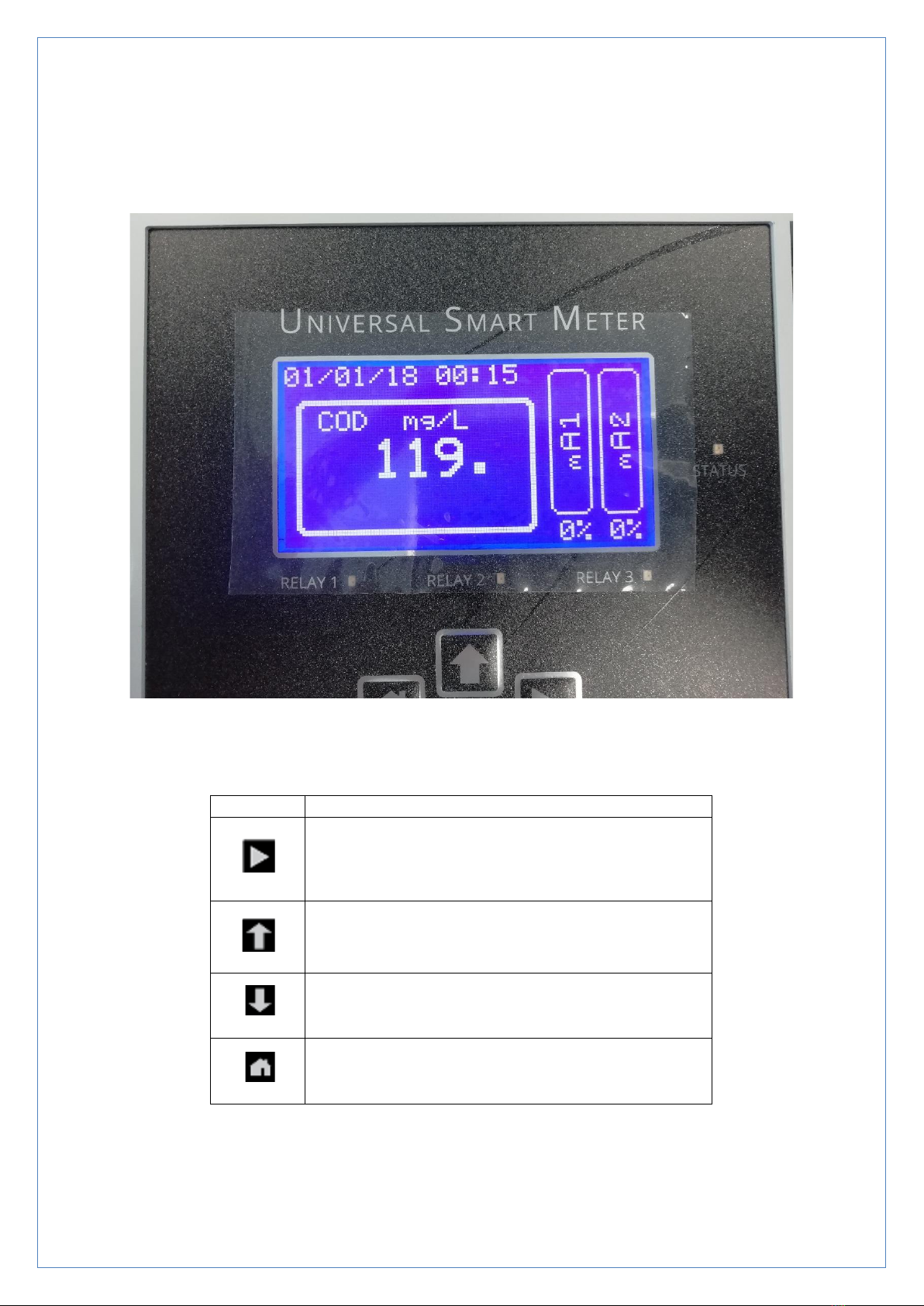
This will be followed automatically by the Home Screen (Figure 2).
Figure 3-3 Home Screen
The Home Screen shows the selected Main Display Parameter (in the selected
units) with a bar graph and percentage indicating either the Level or Distance.
When the unit is first turned on the display will be inaccurate as flow device
parameters will not have been set. Further display options are outlined in
Section 5. The red LED at the side of the display will flash at a rate of 2Hz. This
indicates data is being received.
Pressing the Home Button will return the Display to the Home Screen from
all other display screens.
UNIVERSAL SMART METER COD METER USER MANUAL v2.0.docx page 13 of 50
4. Configuring the USM.
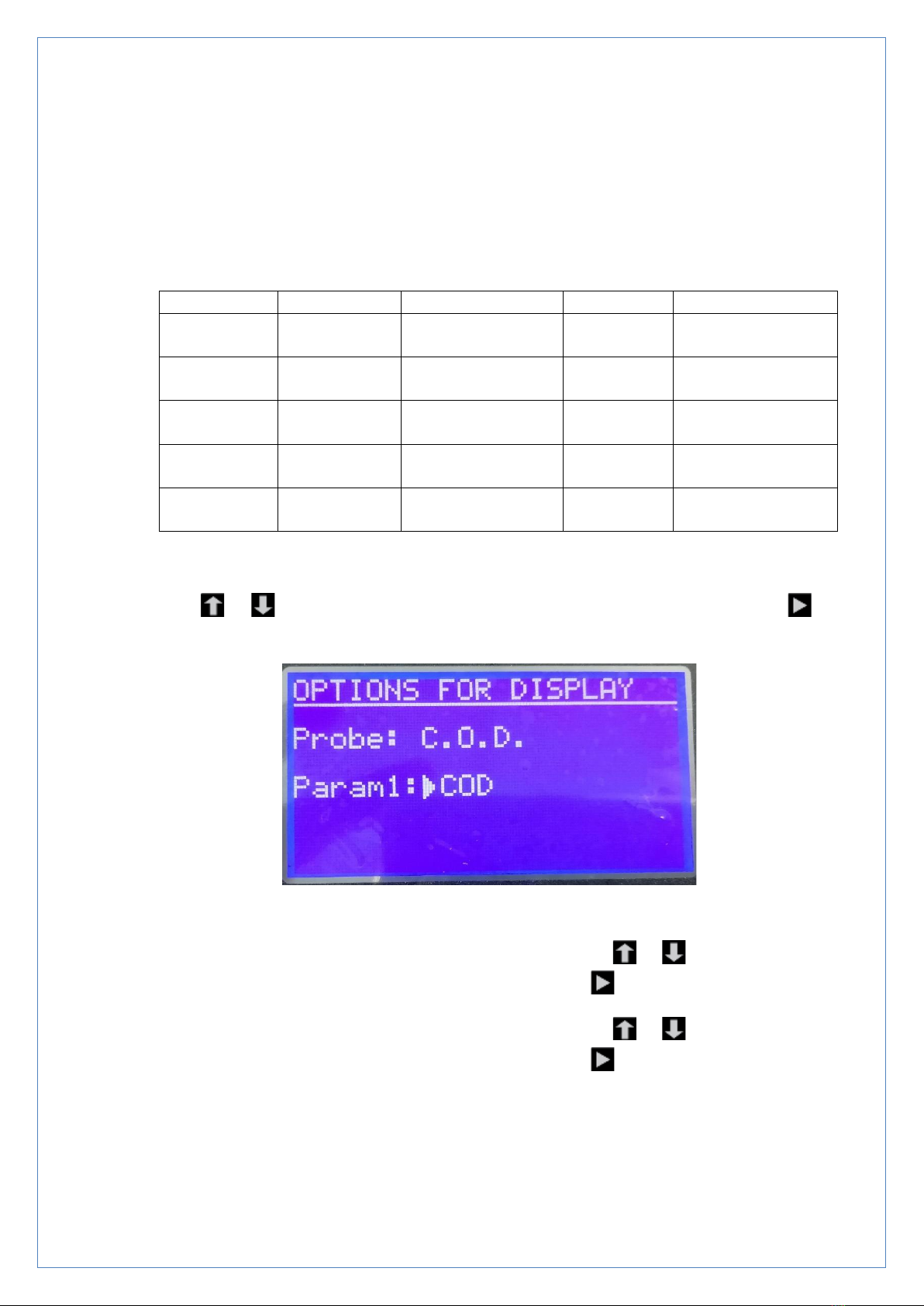
Figure 4-1 USM
The USM is configured using the four push buttons.
Button
Action
Scroll Right or Enter
Scroll up, Increment Numbers
Scroll down, Decrement Numbers
Return to previous menu level or to Home
Screen and Abort
Table 4-1 Key Functionality

UNIVERSAL SMART METER COD METER USER MANUAL v2.0.docx page 14 of 50
4.1. Configuration menu access.
The unit is configured through the MENU page which is password protected.
From the Home Screen, press button to access the PASSWORD page.
Figure 4-2 Password Screen.
Use and buttons to select the desired digit at each location and press
button to select the next digit. If a digit is entered incorrectly press to
return to the Home Screen.
The factory set password to access the configuration menu is '0000'. This
can be changed.
If an incorrect password is entered 3 times the USM will lock the menu for
5 minutes.
If PASSWORD is correct, access to The Configuration MENU page is granted.
Figure 4-3 Configuration Menu Screen

UNIVERSAL SMART METER COD METER USER MANUAL v2.0.docx page 15 of 50
4.2. Configuration Menu.
There are 13 sub menus to the Configuration menu:
1. DIGITAL PROBE SET UP
2. ANALOGUE PROBE SET UP
3. CLEANING CYLCLE SET UP
4. MBUS BMS SET UP
5. 420mA SET UP
6. 420mA TEST
7. RELAY SET UP
8. RELAY TEST
9. NEW USER PASSWORD
10. SET DATE AND TIME
11. SCREEN SAVE MODE
12. LOGGER INTERVAL
13. ENGINEERING MENU
14. MESSAGE SETUP
Use and buttons to align the cursor with required sub menu and press
button to select. The key will return the USM to the Home Screen.
The ENGINEERING menu contains settings which should only be changed by
Smart Storm and requires an additional password.
N.B. When the Configuration Menu is entered, the status of the relays and
the 4-20mA output are not updated.
if no key is pressed for 2 minutes the USM will exit the Configuration Menu
and return to the Home Screen without saving any changes.

UNIVERSAL SMART METER COD METER USER MANUAL v2.0.docx page 16 of 50
4.3. Digital Probe SET UP for UV254.
Use the and buttons to select the DIGITAL PROBE and press to
confirm the selection.
4.3.1.Detect Probe.
Before the probe can be configuredor calibrated it must first be detected.
Use the and buttons to select the DETECT PROBE and press
to confirm the selection.
Figure 4-4 Digital Probe Detect.
Use the or buttons to toggle the selection to ENABLE and press
to confirm the selection (this screen can be used to DISABLE a digital
probe).
The USM will scan the range of Modbus addresses to try to detect the
probe. After a few seconds the result of the scan will appear.
Figure 4-5 Digital Probe Scan Result.
If no probe is detected check the wiring is correct and re-scan for the
probe. If the probe is detected the serial number and address of the
probe will be displayed. The displayed Parameters will be set to first two
measurements returned from the probe –these can be changed in
DISPLAY PARAMS.
Press to return to the Digital Probe menu.
UNIVERSAL SMART METER COD METER USER MANUAL v2.0.docx page 17 of 50
4.3.2.Display Parameters.
The main Digital Probe Display Screen shows two of up to four
parameters measured by the probe in large font.
The default settings after a probe is detected are the first two registers
of the probe.
Probe
Param 1
Param 2
Param 3
Param 4
COD
Temperature
(ºC)
COD
mg/l
BOD
Temperature
(ºC)
BOD
mgl
mg/L
TOC
Temperature
(ºC)
TOC
(mg/L)
Mg/L
DOC
Temperature
(ºC)
DOC
mg/l
UVA
Temperature
(ºC)
UV
%
TSS
mg/l
Table 4-2 Digital Probe Parameters.
To change the displayed parameters. from the Digital Probe Menu, use the
or buttons to move the cursor to DISPLAY PARAMS and press
to confirm the selection.
Figure 4-6 Display Digital Probe Parameters.
The cursor will point at the Param1 value. Use the or buttons to step
through the available measurements and press to confirm the selection.
The cursor will point at the Param2 value. Use the or buttons to step
through the available measurements and press to confirm the selection.
Confirm the settings are to be saved before returning to the Digital Probe
Menu.
UNIVERSAL SMART METER COD METER USER MANUAL v2.0.docx page 18 of 50
4.3.1.What is COD?
COD –Chemical Oxygen Demand
Chemical oxygen demand is the amount of oxygen consumed over a given volume
given in mg/L. Where they differ is that COD is the organic compounds that can be
chemically oxidised.
The measurement of COD is important for the aeration of water during the treatment
process. This is to optimise the levels of oxygen needed to treat and reduce negative
effects on effluent. If the COD is too high, then the receiving waters can be stripped
of their oxygen levels and damage aquatic life.
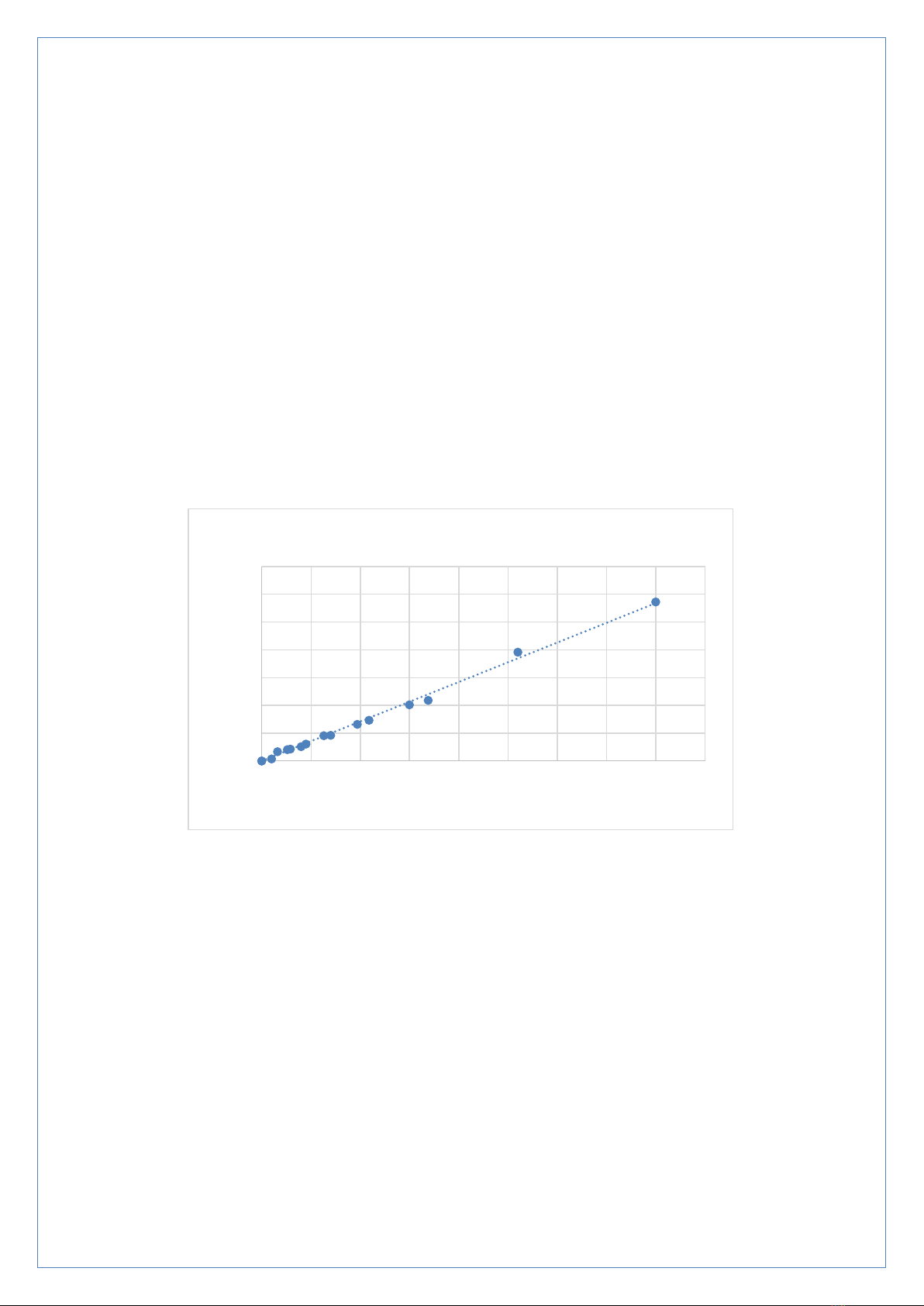
The figure below shows the correlation of UV254 absorption and COD as measured
with the smart storm UV254 probe.
Figure 4-7 COD diagram measurements.
Other than UV254, the measurement of COD for online applications is performed by
combustion process and measuring the oxygen using an IR sensor. This type of
measure can take several minutes
For laboratory measurements there are a number of reagent-based measurements
that in general require a slow incubation period for the detection chemistry to
complete.
0
0.5
1
1.5
2
2.5
3
3.5
050 100 150 200 250 300 350 400 450
Absorbance
COD mg/L
COD Measurements
UNIVERSAL SMART METER COD METER USER MANUAL v2.0.docx page 19 of 50
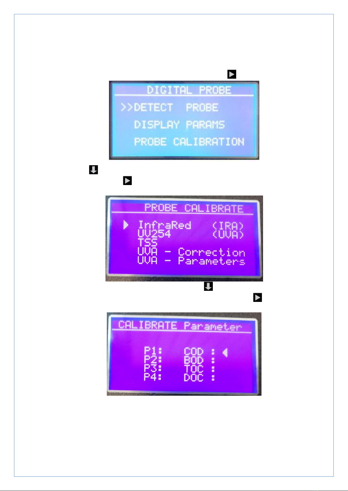
4.3.2.COD Calibration.
•Been in the DIGITAL PROBE settings as below, scroll down to “PROBE
CALIBRATION” and validate with the follow key icon .
Use the key to scroll down to the probe calibration option and validate your
selection using the button. Scroll down to UVA –Parameters to calibrate
COD/BOD/TOC/DOC.
While in the Probe Calibration menu, use the key to scroll down to the
UVA parameters option and validate your selection using the button. The
following screen will allow you to calibrate any chosen parameter.
When you select and validate your parameter such as COD is this case, a
HIGH POINT and LOW POINT calibration option will be display as follow.

UNIVERSAL SMART METER COD METER USER MANUAL v2.0.docx page 20 of 50
First select the high point by using the button.
Now enter you value by using the and buttons and validate your input
to start the high point calibration process with your probe into the COD
solution. This is where the maximum concentration is stored.
After the completion of the high point calibration, restart the above step again
but with the low point calibration option to enable two points calibration. The
low point value can be distilled water which is 0mg/L.
When the calibration is done, SAVE your result and use the home button
to see your main screen display.
BOD –Biochemical Oxygen Demand:
Biochemical oxygen demand is a measurement of the amount of dissolved oxygen
that is need for aerobic biological organisms in a volume of water to break down an
amount of organic material at a given temperature over a certain time period. The
measurement is commonly expressed at mg/L of oxygen consumed in a 5-day
period at 20oC.
The measurement of BOD is not a precise measurement but is widely used for the
indication of the quality of water.
Table of contents
Other Smart Storm Measuring Instrument manuals


