SmarTap e-Valve User manual

INSTALLATION GUIDE

Welcome,
Thank you for using SmarTap –an advanced digital shower system.
Careful adherence to the installation procedures and maintenance
practices set out in this manual will ensure many years of outstanding
performance from your new shower.
Please note,
No part of this publication may be reproduced, stored in a retrieval
system or transmitted in any form by any means, electronic,
mechanical, photo reproductive, recording or otherwise without the
prior written permission of SmarTap Ltd.
This guide is subject to periodic review, update, and revision.
Customers are cautioned to make sure that the guide’s information
applies to the system they are using.
This product performs as described in this guide when assembled,
operated, maintained, and repaired in accordance with the instructions
provided. Do not repair this product or any of its parts other than in
accordance with written instructions provided by SmarTap Ltd.

1 of 51
Table Of Contents
Table Of Contents................................................................................ 1
Introduction.......................................................................................... 2
Important Safeguards .......................................................................... 3
Labels and Symbols ............................................................................ 6
Technical Specifications....................................................................... 7
Package Contents ............................................................................... 8
System Dimensions & Mechanical Specifications ...............................10
Tools...................................................................................................13
Hydraulic Characteristics ....................................................................14
Installation Options.............................................................................15
Plan System Layout............................................................................19
Prepare for Installaiton........................................................................19
Prepare Infrastructure.........................................................................22
Connect e-Valve and Connect Pipes ..................................................30
Connect Controllers............................................................................35
Install Power Supply ...........................................................................37
Connect Cables to e-Valve .................................................................38
Software Outlets Configuration ...........................................................41
Final Inspection ..................................................................................42
Maintenace.........................................................................................43
Troubleshooting..................................................................................46
Notices ...............................................................................................48
2 of 51
Introduction
This guide provides the information necessary to install and operate
the SmarTap digital shower system in a safe and efficient manner.
Please read and understand this guide before operating the
system. It is mandatory to follow the instructions in the guide and the
technical description in order to avoid damage to the system.
If any part of this guide is not clear, please contact SmarTap Technical
Support at support@smartap-tech.com for clarification.
Warnings / Cautions / Notes
The manual includes several kinds of comments, marked with specific
statements and aimed to attract user attention to a specific type of
information.
The definitions of Warnings, Cautions and Notes used in this document
are as follows:
WARNING
A WARNING HIGHLIGHTS AN ESSENTIAL OPERATING OR
MAINTENANCE PROCEDURE, PRACTICE, CONDITION,
STATEMENT, ETC., WHICH, IF NOT STRICTLY
OBSERVED, COULD RESULT IN INJURY OR DEATH OF
PERSONNEL, OR LONG TERM HEALTH HAZARDS.
CAUTION
A CAUTION HIGHLIGHTS AN ESSENTIAL OPERATING OR
MAINTENANCE PROCEDURE, PRACTICE, CONDITION,
STATEMENT ETC., WHICH, IF NOT STRICTLY OBSERVED,
COULD RESULT IN DAMAGE TO, OR DESTRUCTION OF,
EQUIPMENT OR LOSS OF EFFECTIVENESS.
NOTE
A NOTE HIGHLIGHTS OR CLARIFIES AN ESSENTIAL
SYSTEM DESCRIPTION, OPERATING OR MAINTENANCE
PROCEDURE, CONDITION OR STATEMENT.
3 of 51
Important Safeguards
Please read these instructions carefully before installation.
Read Instructions
All the safety and operating instructions should be read before system
is unpacked and installed.
Retain Instructions
The safety and operating instructions should be retained for future
reference.
Follow Instructions
All installation and configuration instructions should be followed.
WARNING
THE WARRANTY WILL BE VOID IF THE PRODUCT IS
NOT INSTALLED ACCORDING TO THESE
INSTRUCTIONS. SMARTAP WILL NOT BE LIABLE FOR
LOSS OR DAMAGES RESULTING FROM IMPROPER
INSTALLATION OR USE OF THE PRODUCT THAT IS
NOT IN ACCORDANCE WITH THE INSTRUCTIONS
SPECIFIED BELOW.
NOTE
THE CONTENTS OF THIS GUIDE ARE SUBJECT TO
CHANGE WITHOUT PRIOR NOTICE.
Safety Instructions
WARNING
DO NOT USE THE E-VALVE SYSTEM BEFORE
READING AND UNDERSTANDING THIS GUIDE
4 of 51
WARNING
UNAUTHORIZED MODIFICATION MAY CAUSE POOR
PERFORMANCE OF THE E-VALVE. DO NOT MAKE
MODIFICATIONS TO THE VALVE AS THIS COULD
ADVERSELY AFFECT THE PERFORMANCE OF THE
VALVE AND VOID THE WARRANTY. SMARTAP WILL
NOT BE LIABLE UNDER ITS WARRANTY OR
OTHERWISE FOR PERSONAL INJURY OR DAMAGE
CAUSED BY AN UNAUTHORIZED MODIFICATION.
WARNING
PRODUCT MUST BE INSTALLED BY QUALIFIED AND
CERTIFIED PERSONNEL, IN ACCORDANCE WITH ALL
CURRENT RELEVANT STATUTES AND REGULATIONS
IN YOUR COUNTRY.
WARNING
ALL SHOWERS REQUIRING AN ELECTRICAL
CONNECTION MUST BE INSTALLED BY QUALIFIED
PERSONEL FOLLOWING THE RELEVANT
REGULATIONS IN YOUR COUNTRY AND CERTIFIED TO
CURRENT BUILDING REGULATIONS.
WARNING
BEFORE ANY ELECTRICAL CONNECTIONS ARE MADE,
THE ELECTRICITY SUPPLY MUST BE TURNED OFF AT
THE MAINS SWITCH. ALL ELECTRICAL INSTALLATION
MUST BE CARRIED OUT ONLY BY QUALIFIED
PERSONNEL.
CAUTION
BE CAREFUL WHILE UNPACKING; THE SYSTEM IS
FRAGILE.
5 of 51
Installation Guidelines
CAUTION
THE E-VALVE SHOULD BE INSTALLED IN AN
ACCESSIBLE LOCATION FOR MAINTENANCE (AND NO
WARRANTY CLAIM CAN BE CONSIDERED OR
LIABILITY ACCEPTED BY SMARTAP IF LACK OF
ACCESSIBILITY HAS PREVENTED MAINTENANCE).
CAUTION
THE E-VALVE MUST NOT BE INSTALLED IN PLACES
WHERE EITHER THE AMBIENT TEMPERATURE IS
LIKELY TO EXCEED 40°C OR WHERE FREEZING MAY
OCCUR.
THE DIAL CONTROLS MUST NOT BE INSTALLED IN
PLACES WHERE THE AMBIENT TEMPERATURE IS
LIKELY TO FALL BELOW 5°C OR RISE ABOVE 60°C.
CAUTION
TO PREVENT DAMAGE IN THE EXISTING
INFRASTRUCTURE IT IS MOST RECOMMENDED TO
CHECK FOR HIDDEN PIPES OR CABLES BEFORE
DRILLING ANY HOLES.
PIPES ON BOTH INLET AND OUTLETS SHOULD BE AS
SHORT AS POSSIBLE IN ORDER TO AVOID
REDUCTION OF FLOW RATE AT THE CONNECTED
OUTLETS.
6 of 51
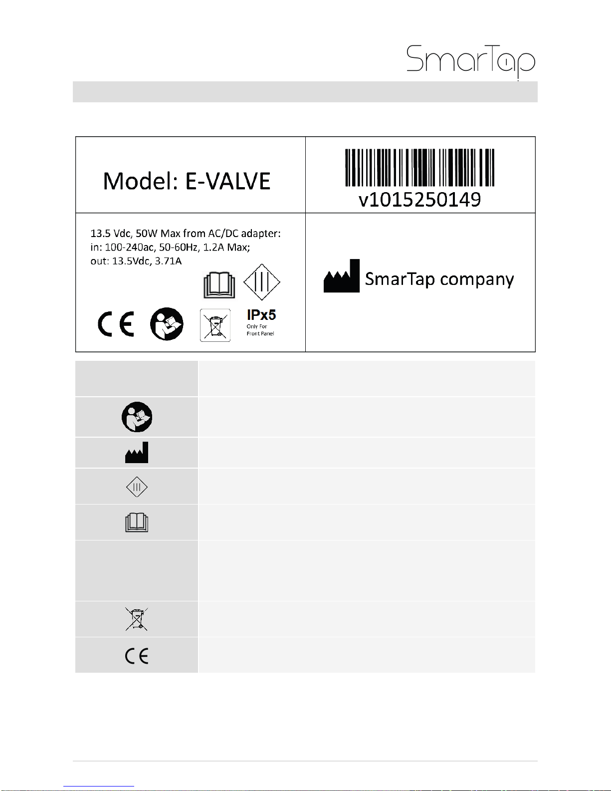
Labels and Symbols
The e-Valve system has the following labels and symbols.
Symbol
Description
Read the Installation manual
Manufacturer
Class III Appliance
Read all documents including the User’s Guide
IPx6
IPx6 Water projected by a nozzle (6.3 mm)
against enclosure from any direction shall have
no harmful effects.
Not for general waste
CE conformity marking

7 of 51
Technical Specifications
Absolute Maximum Ratings
Working pressure
1 –9 bar
Overpressure
16 bar
Burst pressure
35 bar
Hot water temperature
70 Co
Ambient temperature
5 –60 Co
Relative humidity
90% non-condensing
Recommended Conditions
Working pressure
2 –5 bar
Hot water temperature
50 –65 oC
Cold water temperature
10 –25 oC
Set point temperature
Cold water or 35 –45oC
Performance at Recommended Conditions
Temperature accuracy
±0.5°C
Flow accuracy
±5% of Full Scale
Hydraulic performance
Complies with EN1111 standard
Miscellaneous
Supplied user interface
cable length
9m
Operational voltage
100 –240V ~ 50 –60Hz
Standards
Safety: EN 60335-1 :2012,
EN60335-2-105:2005
EMC: EN 55014-1, EN 55014-2
CE, RoHS, WRAS
WARNING
DO NOT USE THE SYSTEM IF THESE CONDITIONS
ARE NOT MET.

8 of 51
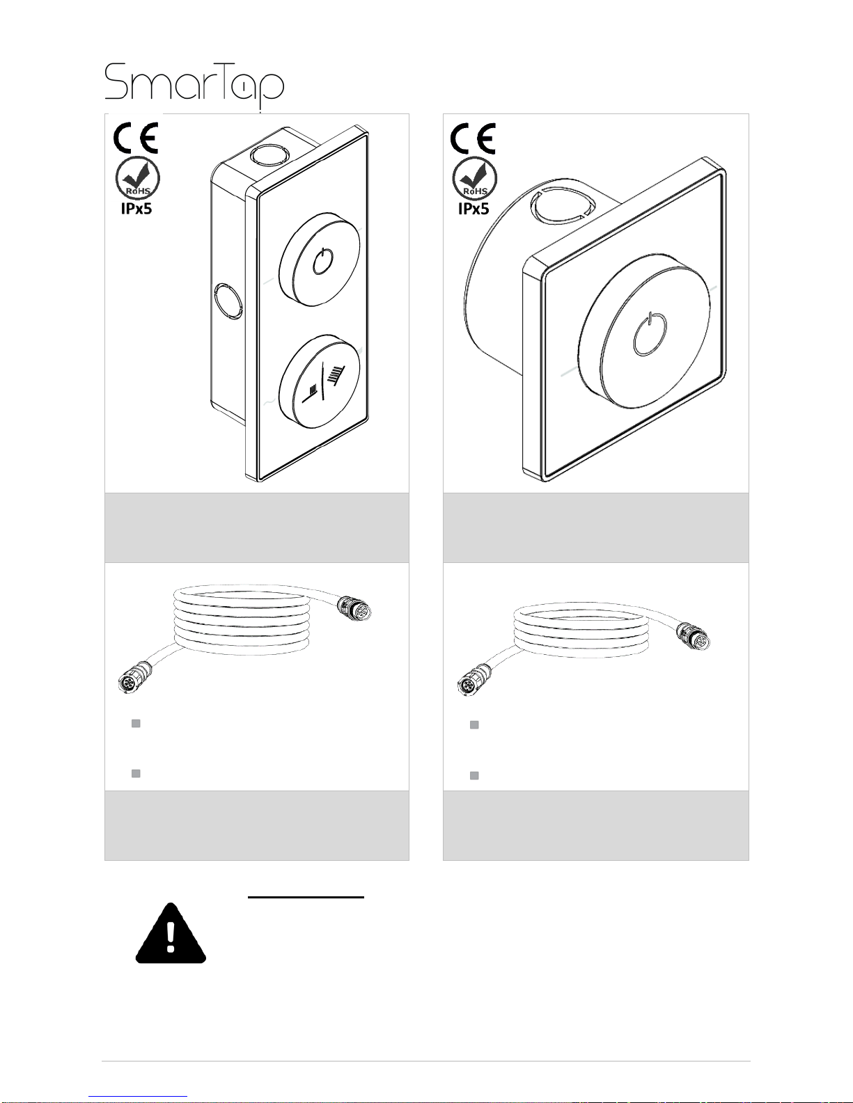
Package Contents
The SmarTap Digital Shower system package includes the following
components:
AC cord length: 1.5m
DC cord length: 1.5m
e-Valve
AC/DC Adaptor
9 of 51
WARNING
IF THE SYSTEM PARTS SHOW ANY KIND OF
MECHANICAL DAMAGE, DO NOT USE THE SYSTEM
AND CONTACT A SMARTAP REPRESENTATIVE FOR
SERVICE.
Two Dial controller
(If applicable) One Dial
controller
6 pin interface cable 9 m
length
IP67 compatible
6 pin interface cable 7m
length
IP67 compatible
Two Dial controller cable
(If applicable) One Dial
controller cable

10 of 51
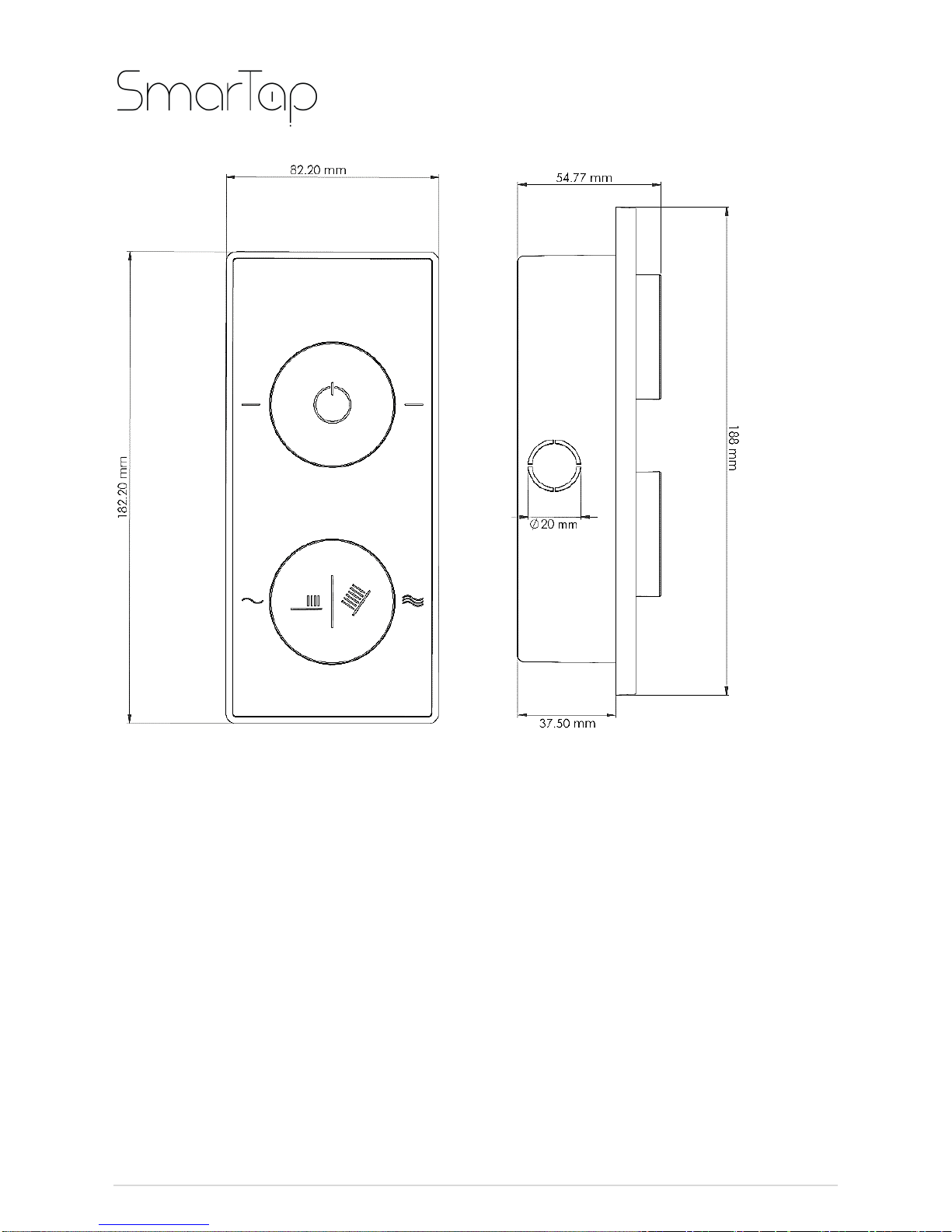
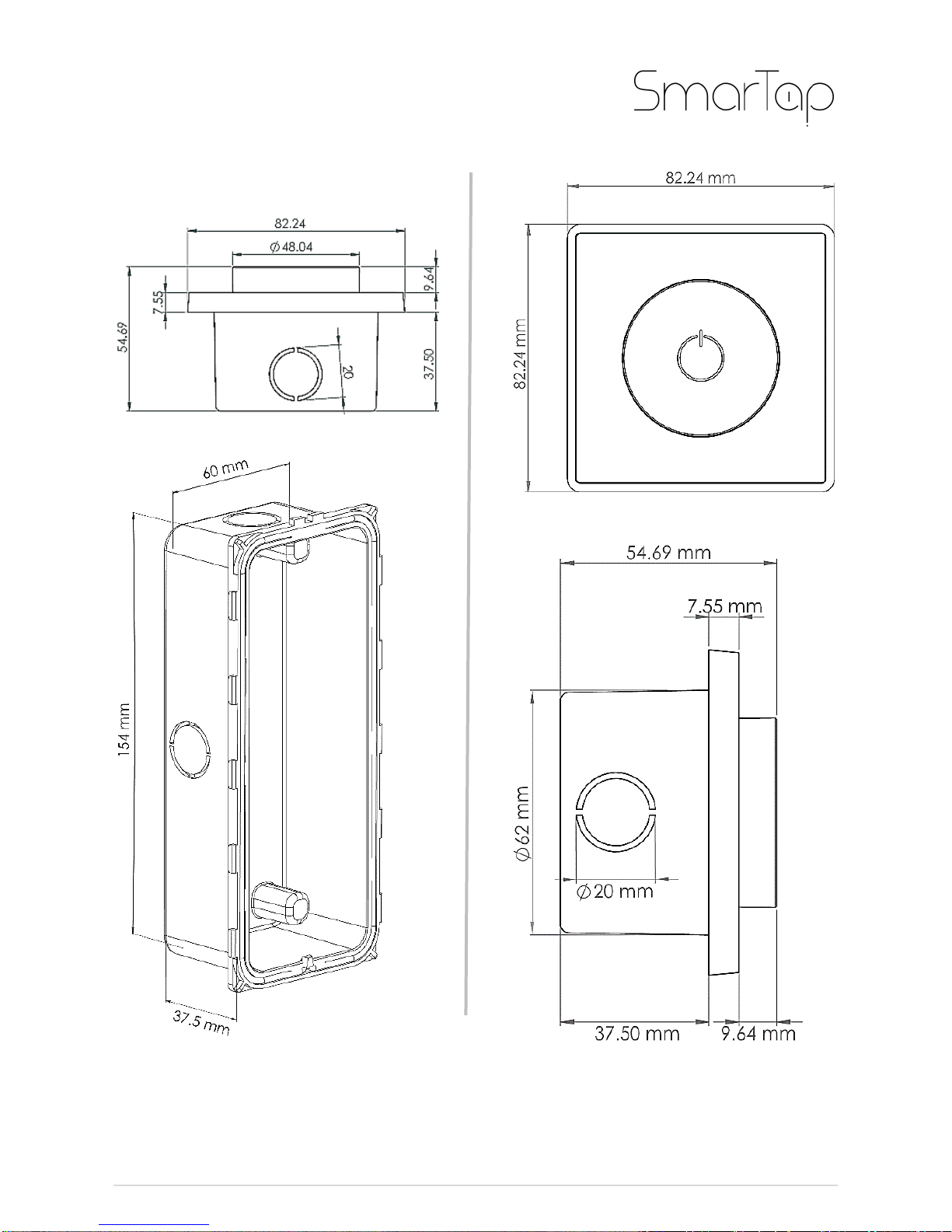
System Dimensions & Mechanical Specifications
e-Valve
11 of 51
Two Dial Controller
12 of 51
One Dial Controller
13 of 51
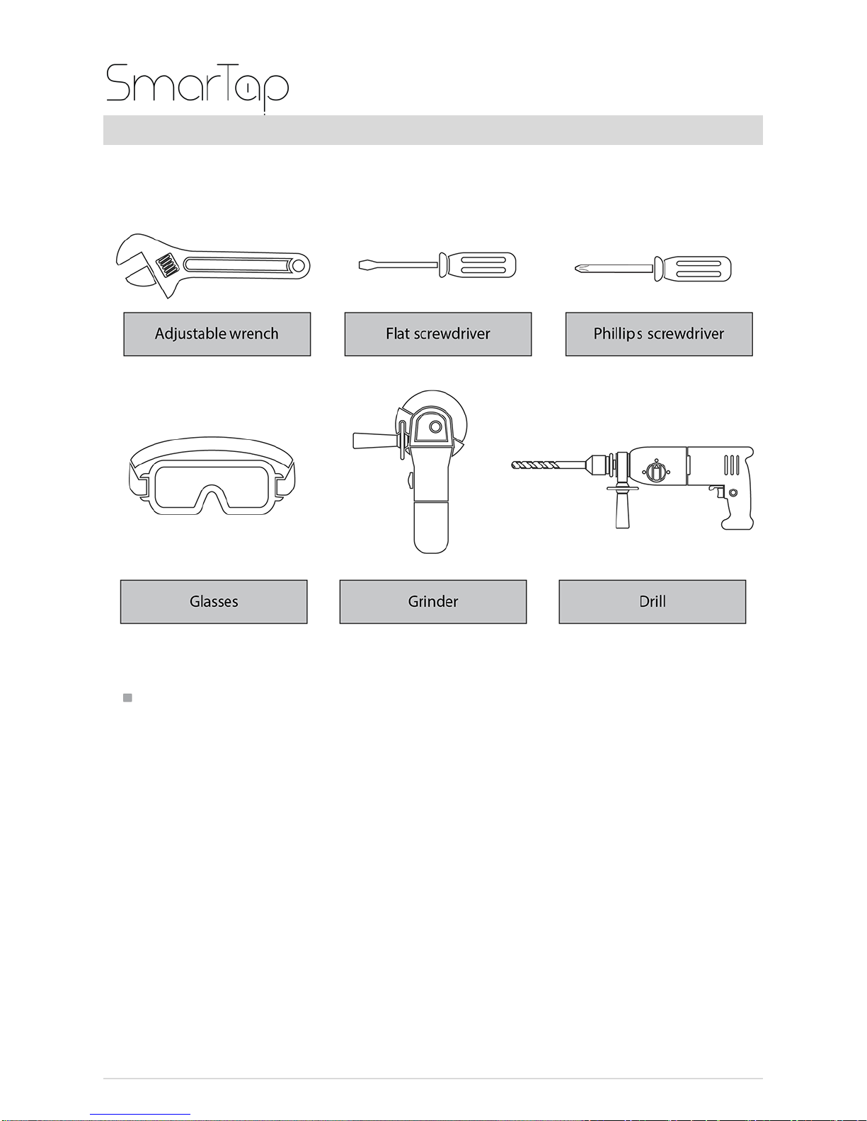
Tools
For installation of the SmarTap digital shower product, you will need
the following tools:
(If Applicable) For the One Dial controller, use a 62mm hole saw.

14 of 51
Hydraulic Characteristics
Typical flow rate performance of e-Valve at various inlet and outlet
conditions
0
5
10
15
20
25
30
35
40
0.5 1 1.5 2 2.5 3 3.5 4 4.5
Flow rate, mixed stream [L/min]
Dynamic pressure [bar]
Single outlet, open Single outlet, resistance class C
Two or three outlets, open
15 of 51
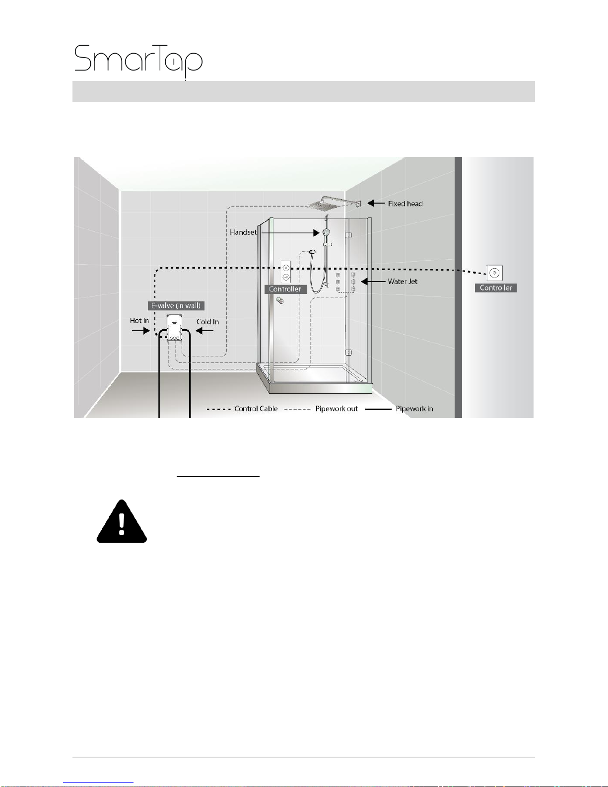
Installation Options
Shower - Concealed Installation (In wall): Fixed head,
Handset, Water Jets
WARNING
THE POWER CABLE MUST BE SECURED AND CHASED
INTO THE WALL. IT MUST NOT BE LEFT EXPOSED TO
KEEP IT PROTECTED IN THE EVENT OF A POSSIBLE
LEAK.
PLEASE MAKE SURE THAT THE CABLE IS INSTALLED
BY A QUALIFIED ELECTRICIAN.

16 of 51
Bath - Concealed Installation (Under bath): Fixed head,
Handset, Bath overflow filler
WARNING
THE POWER CABLE MUST BE SECURED AND CHASED
INTO THE WALL. IT MUST NOT BE LEFT EXPOSED TO
KEEP IT PROTECTED IN THE EVENT OF A POSSIBLE
LEAK.
PLEASE MAKE SURE THAT THE CABLE IS INSTALLED
BY A QUALIFIED ELECTRICIAN.

17 of 51
Shower –Loft Mounted: Fixed head, Handset, Water
Jets
WARNING
THE POWER CABLE MUST BE SECURED AND CHASED
INTO THE WALL. IT MUST NOT BE LEFT EXPOSED TO
KEEP IT PROTECTED IN THE EVENT OF A POSSIBLE
LEAK.
PLEASE MAKE SURE THAT THE CABLE IS INSTALLED
BY A QUALIFIED ELECTRICIAN.

18 of 51
Bath –Loft Mounted (Under bath): Fixed head, Handset,
Bath overflow filler
WARNING
THE POWER CABLE MUST BE SECURED AND CHASED
INTO THE WALL. IT MUST NOT BE LEFT EXPOSED TO
KEEP IT PROTECTED IN THE EVENT OF A POSSIBLE
LEAK.
PLEASE MAKE SURE THAT THE CABLE IS INSTALLED
BY A QUALIFIED ELECTRICIAN.
Table of contents
Popular Control Unit manuals by other brands

BriskHeat
BriskHeat ACR 3 MiniPRO Hot Bonder instruction manual

Oeffler-Baustoffe
Oeffler-Baustoffe RD 4 203 Series manual

Pratissoli
Pratissoli S723 operating instructions

Allmatic
Allmatic BIOS1 24V manual

Vag
Vag GA INDUSTRIES 983-D Installation, operation and maintenance manual

DeZurik
DeZurik KSL-SD instructions


Texas Instruments
Texas Instruments TCAN1046V user guide

Allen-Bradley
Allen-Bradley DH485/RS-232C installation instructions

Emerson
Emerson Anderson Greenwood 9300 Series Installation and maintenance instructions

Honeywell
Honeywell ScanDome ll HTX-3000 instruction manual

Laird
Laird BTM410 user manual

Siemens
Siemens ZIC-4A Installation instructions manual