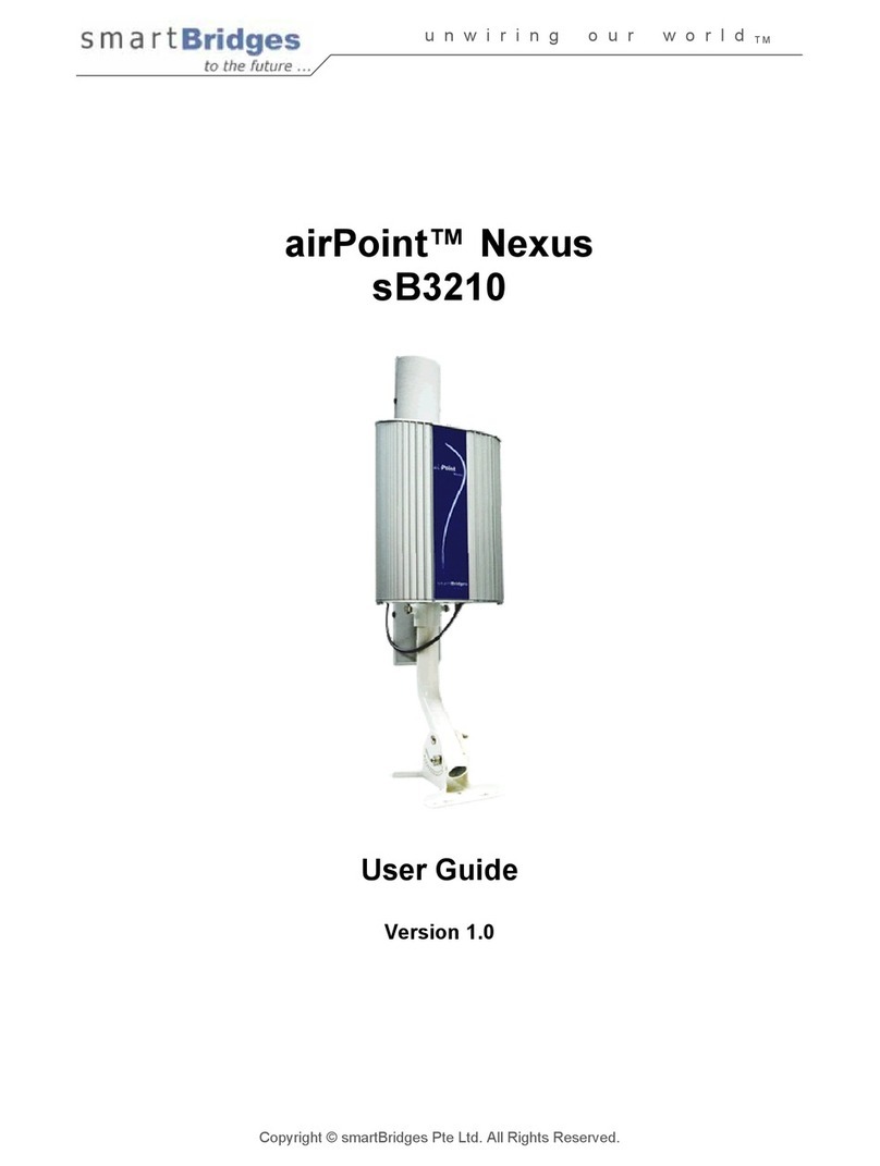
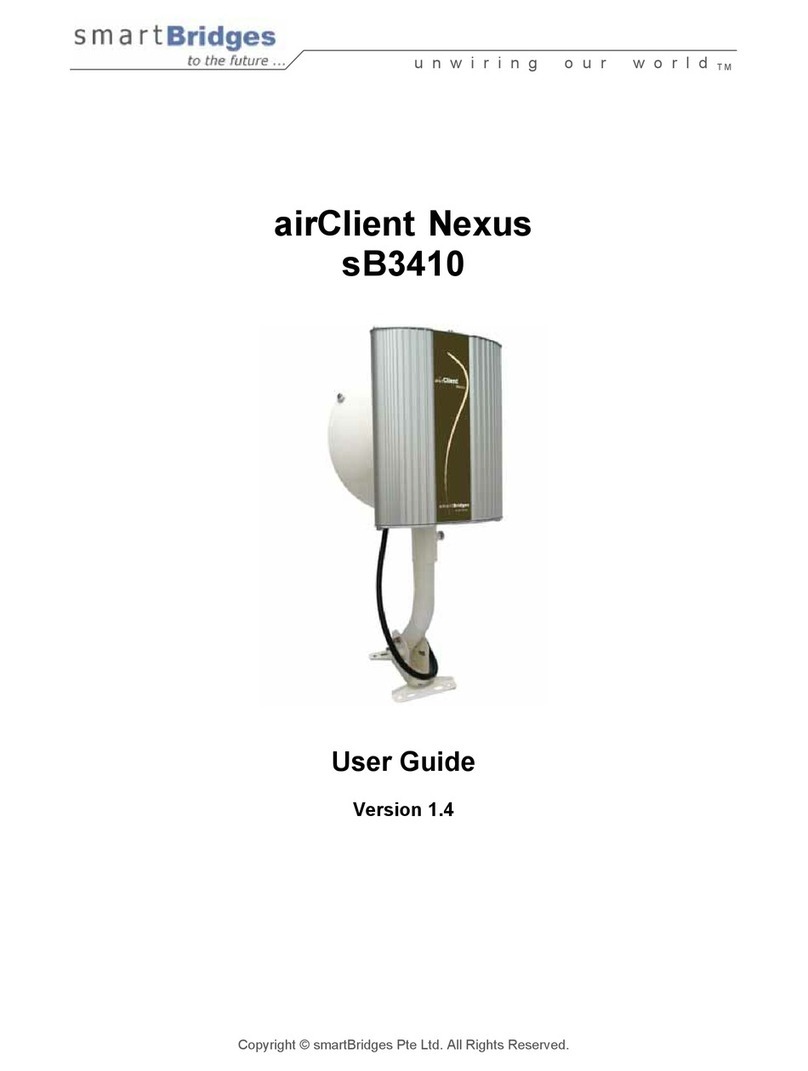
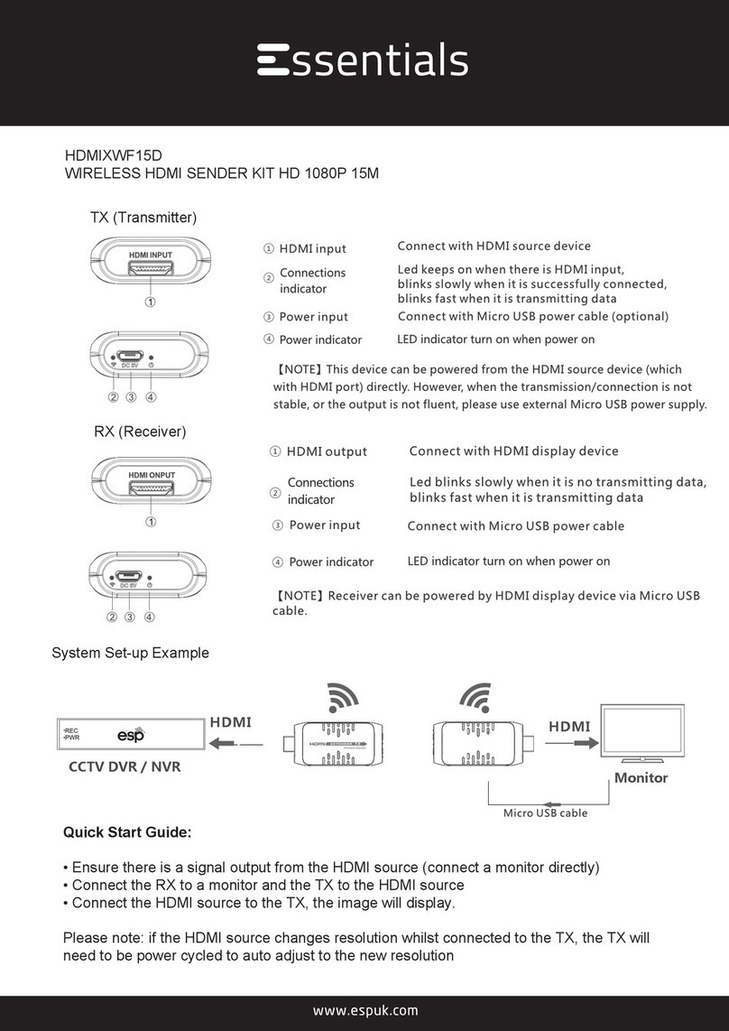
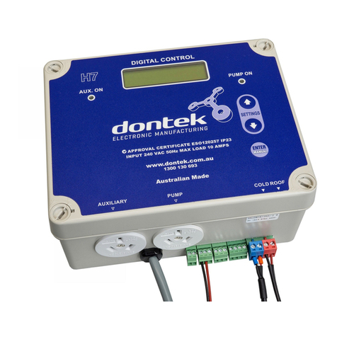
SmartBridges airHaul Nexus PRO TOTAL User manual


unwiring our world™
i
Intelligent Wireless Platform
Contents
Chapter 1 Preface 1
Chapter 2 Before you Begin 3
Safety Precautions and Pre-installation Information
• Safety Precautions
• Required Tools and Cables
• Package Contents
Chapter 3 Installation 7
Overview of the Installation Process
• Typical Radio System Installation
• Connections
• Powering and Resetting the Unit
Chapter 4 Mounting 15
Important Considerations when Choosing
the Mounting Location
• Link Distance
• Signal Path Clearance (Fresnel Zone)
Mounting the Nexus Radio Equipment.
• Tower or Pole Mounting
• Wall Mounting
Chapter 5 Antenna Alignment Overview 21
Instructions on Aligning the Antennas
Appendix A Declarations of Conformity 23
Appendix B Warranty Information 29


Intelligent Wireless Nexus Platform
unwiring our world™
1
Chapter 1 - Preface
This Installation Guide is for the networking professional who installs and manages the
smartBridges’ Intelligent Nexus Platform of Wireless Backhauls, Access Points and Client
devices. The smartBridges’ TOTAL series of products come with an integrated antenna
contained within the enclosure for simple out-of-the-box installation.
• airHaul Nexus PRO™ TOTAL (sB3012)
• airHaul™ Nexus TOTAL 241 (sB3013)
• airHaul™ Nexus TOTAL 551 (sB3014)
• airPoint Nexus PRO™ TOTAL (sB3212V or H)
• airPoint™ Nexus TOTAL 241 (sB3213V)
• airPoint™ Nexus TOTAL 551 (sB3214V)
• airClient Nexus PRO™ TOTAL (sB3412)
• airClient™ Nexus TOTAL 241 (sB3413)
• airClient™ Nexus TOTAL 551 (sB3414)
• airClient™ TOTAL 241 (sB3415)
The initial hardware installation, setup and mounting of the equipments are explained in this
guide. To install smartBridges’ products, you need to have a fundamental understanding of
Radio Frequency (RF) and networking.
In Chapter 2, you will nd safety precautions as well as a list of the box contents and tools
needed for installation. The installation process, which can be completed before mounting
the unit in the outdoor environment, is explained in Chapter 3.
Chapter 4 describes how to conduct a site survey to choose a suitable mounting location
and outlines the mounting process for various congurations. Instructions are also provided
on safely grounding the units.
Finally in Chapter 5, the antenna alignment process is explained.
Related Publications
These documents provide complete information about each product in the TOTAL series of
radio equipments.
• User Guide
• Release Notes
• Technical Specication
For the latest information on the products, please visit our website at
http://www.smartbridges.com/

2
unwiring our world™
Technical Support Center
Comprehensive technical support by dedicated smartBridges engineers is available to
all customers through the smartBridges support center website. The website provides
updated tools and documents to help troubleshoot and resolve technical issues related to
smartBridges products and technologies. To access the technical support resources, please
visit the support center website at http://www.smartbridges.com/support/
You will need to register for certain services and downloads on the smartBridges support
center website.
Chapter 1 - Preface

Intelligent Wireless Nexus Platform
unwiring our world™
3
Chapter 2 - Before you Begin
This chapter provides the safety precautions that you need to follow while installing and
operating the smartBridges units. It contains the following sections:
• Safety Precautions
• Required Tools and Cables
• Box Contents
Safety Precautions
For your safety and to achieve a proper working installation, please read and follow
these safety precautions:
1. Only trained and qualied personnel should install, replace, or service this
product.
2. Select your installation site with safety and performance in mind. Conduct a
proper site survey before deployment.
3. Discuss your plans for installation with your power company. Ask them to visit
your proposed installation site.
4. Plan your installation carefully and completely before you begin. Never perform
the installation alone.
5. Do not locate the product near overhead power lines, circuits or electrical light
sources or where it can come into contact with them. During installation, take
extreme care not to come into contact with such circuits, as they may cause
serious injury or death. For proper installation and grounding of the equipment,
please refer to national and local codes.
Note:
Electric power lines and telephone lines look alike.
6. This product must be grounded. Never operate the equipment in the absence of
a suitably installed ground conductor. Contact the appropriate electrical
inspection authority or an electrician if you are uncertain whether suitable
grounding is available.

4
unwiring our world™
7. When installing the products, remember:
a. Not to use a metal ladder.
b. Not to work on a wet or windy day or when there is lightning.
c. To dress properly: wear shoes with rubber soles and heels, rubber gloves and
long sleeved shirt or jacket.
8. If any part of the equipment should come into contact with a power line, do not
touch it or try to remove it yourself. Call your local power company to have it
removed safely. If an accident occurs involving power lines, please call for
qualied emergency help immediately.
9. Do not work on the equipment or connect or disconnect cables during periods of
lightning activity.
10. Do not operate this product near unshielded blasting caps or in an explosive
environment.
11. In order to comply with Radio Frequency (RF) exposure limits, the antennas for
this product should be positioned at not less than 6.6 ft (2 m) from the human
body.
Required Tools and Cables
You will require the following tools to mount the TOTAL unit:
• 6 mm wrench or socket
• #2 Phillips screwdriver
• Crimping tool
• You may also require tools for user-supplied hardware or fasteners
• CAT5 cable of required length. smartBridges recommends the use of a shielded
CAT5 cable rated for outdoor use.
Box Contents
Each TOTAL unit box contains the items listed below. Ensure that all items are included in
the shipment. Notify your vendor if any item is damaged or missing.
1. TOTAL unit
2. Power over Ethernet (PoE) Injector (with mounting screws placed inside the
enclosure)
3. Power module and AC power cord
Chapter 2 - Before you Begin

Intelligent Wireless Nexus Platform
unwiring our world™
5
4. User Guide (Documentation CD)
5. Drilling Template
6. Mounting bracket
7. Quick Installation Guide (this document)
Figure 2-1 Photos of Accessories packed with TOTAL unit.
Note:
The smartBridges equipment shipping box is designed to be eco-friendly.
99.9% of packaging material by weight is bio-degradable.
123
4
7
6
5

6
unwiring our world™
8. An accessories pouch that contains the following items:
a. M8 mm Anchor Hex nuts (4 pieces)
b. M8 mm Anchor washers (4 pieces)
c. M8X60 mm Anchor bolts (4 pieces)
d. M8 mm SS nuts (4 pieces)
e. M8 mm SS plain washers (4 pieces)
f. M8 mm SS spring washers (4 pieces)
g. M8X75 mm SS bolts (4 pieces)
Chapter 2 - Before you Begin
a
b
cd
e
f
g

Intelligent Wireless Nexus Platform
unwiring our world™
7
Chapter 3 – Installation
This chapter provides the hardware installation information for smartBridges’ TOTAL series
of products which come with an integrated antenna. It shows the steps for installation and
connections of all the components before mounting in the outdoor location. This chapter
includes the following sections:
• Typical Radio System Installation
• Connections
• Powering and Resetting the Unit
Typical Radio System Installation
These units are designed to be mounted in an outdoor environment, typically on a tower
or building. The units are shipped with all the required accessories for an out-of-the-box
installation. For mounting information, please refer to Chapter 4.
Figure 3-1 below gives an overall view of how the conguration should look like once you
have completed the installation procedures outlined in this chapter and chapter 4.
Figure 3-1 Connections for smartBridges’ TOTAL unit

8
unwiring our world™
PoE Injector Connections
After grounding the PoE Injector, it can be mounted on a wall or secured otherwise in an
accessible location. Figure 3-3 illustrates the placement of the RJ11 and RJ45 cables.
Figure 3-3 PoE Injector Indicators and Connectors
Connecting the PoE Injector:
1. Connect the PoE Injector to the power module via the PWR IN RJ11 jack
(see Figure 3-3).
2. Connect the PoE Injector to the computer or network via the ETH IN RJ45 jack
(see Figure 3-3).
3. Connect the PoE Injector via the RJ45 jack running from the ETH OUT port on
the back to the Ethernet Port ETH A on the unit (as shown in Figures 3-4a and
3-4b).
Note:
The RJ45 cable connector pin needs to be removed and re-attached
in order to t the ETH port gland on the unit. This is to ensure that the
connections are fully weather-proofed. Please refer to the following
instructions on connecting the RJ45 cable.
Chapter 3 - Installation

Intelligent Wireless Nexus Platform
unwiring our world™
9
Figure 3-4a Connections on the PRO TOTAL unit
Figure 3-4b Connections on the airHaul and airPoint Nexus TOTAL 241 units (Low Band)

10
unwiring our world™
Figure 3-4c Connections on the airHaul and airPoint Nexus TOTAL 551 units (High Band)
Figure 3-4d Connections on the airClient Nexus TOTAL 241 (Low Band) and
airClient Nexus TOTAL 551 (High Band) units
Figure 3-4e Connections on the airClient TOTAL 241 (Low Band) unit
Chapter 3 - Installation

Intelligent Wireless Nexus Platform
unwiring our world™
11
RJ45 Cable Connection:
1. Remove the RJ45 connector pin from the cable using pliers or other tool and
pass the cable through the ETH gland outer and inner covers as shown in
gure 3-5.
2. Remove 5mm of the outer shield cover for each colored inner cable and trim
them.
3. Match the color of each cable sequentially to the other end with respect to the
connector pin number and place it in the connector slot.
4. Use the crimping tool to crimp the cables and re-attach the RJ45 connector pin.
5. Screw on the inner gland cover onto the unit and then screw on the outer gland
cover onto the inner gland cover. Ensure that the cable is covered completely by
the outer gland cover with no room for water to enter.
Figure 3-5 Crimping the RJ45 Cable
Note:
The second RJ45 port, ETH B, as shown in Figure 3-4a/b/c, is available for
daisy chaining to another device. To connect the second device, follow the
procedure as outlined above. This is not applicable for the airClient Nexus
TOTAL (sB3413 and sB3414) and airClient TOTAL (sB3415) which does not
have a second ethernet port.
Outer Gland Cover
Inner Gland Cover RJ45 Connector Pin

12
unwiring our world™
Antenna Connections
The TOTAL series of products provides the exibility of using an external antenna through
the N-Connector.
Note:
This is not applicable for the airClient Nexus TOTAL (sB3413 and sB3414)
which do not have an external antenna connector.
To connect the external antenna:
1. Connect the antenna RF cable to the correct N-Connector (please see
Figure 3-4a/b/c/e).
After completing all the connections, the radio system should look similar to the following
gure.
Figure 3-6 Typical TOTAL radio system
Powering and Resetting the Unit
After performing the installations and connections as shown in Figure 3-6, you may boot up
Chapter 3 - Installation

Intelligent Wireless Nexus Platform
unwiring our world™
13
and log in to the unit using the Web GUI. It is recommended that the unit be congured and
tested on the bench before mounting in the outdoor location to ensure that it is performing
satisfactorily. Please refer to the relevant product User Guide for conguration information.
You can access the User Guide from the support center website at
http://www.smartbridges.com/support/
In order to return the device to default factory settings, you may use the reset button on
the side of the PoE Injector to reset the unit. You will need to press and hold the reset
button using a small pointed object such as a paperclip for 15-20 seconds. Refer to Fig 3-3.
During boot up, reset or other operations, the LED display will ash according to the table
below.
Table 3-1 LED Display
Conditions ETH A ETH B Radio RF
Boot up Alternate ash Alternate ash Off
Reset Simultaneous
Flash
Simultaneous
Flash
Simultaneous
Flash
Restore defaults Simultaneous
Flash
Simultaneous
Flash
Simultaneous
Flash
Firmware Upgrade
Simultaneous
Flash during the
whole process
Simultaneous
Flash during
the whole
process
Simultaneous
Flash during the
whole process
Associated as
Remote/NAT/
Router
Continuous Glow
(if Ethernet Link is up)
Continuous Glow
Not associated
as Remote/NAT/
Router
Regular Blink
As Root Device Fast Burst Blink
Note:
For the airClient Nexus TOTAL (sB3413 and sB3414) and airClient TOTAL
(sB3415), please refer to the column for ETH A only as it does not have a
second ethernet port (ETH B).

14
unwiring our world™
Chapter 3 - Installation

Intelligent Wireless Nexus Platform
unwiring our world™
15
Chapter 4 - Mounting
This section describes how to physically mount the smartBridges’ TOTAL series of products
on the site. The chapter contains the following sections:
• Important Considerations when Choosing the Mounting Location
1. Link Distance
2. Signal Path Clearance (Fresnel Zone)
• Mounting the TOTAL Unit
1. Tower or Pole Mounting
2. Wall Mounting
• Changing Antenna Polarization
Important Considerations when Choosing the Mounting
Location
Each Radio Frequency (RF) application is a unique installation. A site survey is needed
to determine the optimum use of the TOTAL unit to optimize link distance, coverage, and
network performance. The most important considerations are link length and clearance from
obstacles.
The following operating and environmental conditions should be taken into account when
performing a site survey:
• Data rates - Sensitivity and range are inversely proportional to data bit rates. The
data rate increases with a decrease in link distance and/or decrease in receiver
sensitivity.
• Antenna placement - Proper antenna conguration is critical in maximizing radio
range in maximizing radio range. In general, greater heights allow for longer
distances and the avoidance of obstructions. However, do not install the TOTAL
unit at the extreme top of a tower, radio mast or high building to minimize risk of
being directly struck by lightning. It is advisable to install it at least 2 feet below
such heights. Extra height may also increase potential interference from other
unlicensed radio systems.
Note:
Do not install the unit in the proximity of a TV or Radio receiving mast.

16
unwiring our world™
• Physical environment - Clear, open areas provide better radio range than
enclosed, crowded areas. Physical obstructions such as buildings, trees, or hills
can hinder performance of wireless devices. Avoid locating the TOTAL unit
where there is an obstruction between the sending and receiving antennas.
1. Link Distance
If there is no obstacle in the signal path, the maximum link distance depends primarily on the
type of antenna and the free space path loss. Ensure that your proposed mounting site is
within range of the remote antenna. To help estimate the range, the TOTAL unit has a built-in
Link Budget Calculator under Tools in the Web GUI which is accessible upon logging into
the unit. Please refer to the product User Guide for more information on this tool.
2. Signal Path Clearance (Fresnel Zone)
A radio beam travels from one antenna to another in a straight line. Therefore, the path
between the antennas must be free of major obstacles. The effects of obstacles and terrain,
both along and near the path, have a signicant bearing on the propagation of radio signals
and can cause both interference and signal cancellation.
When choosing a site, consider the effects of the following common obstacles:
• Trees and large plants - A tree directly in the signal path can completely block the
signal. You can avoid this by leaving sufcient clearance above the treetops.
You may need to leave extra clearance above smaller tress to allow for future
growth into the signal path.
• Man-made obstacles - A large round building such as a gas storage
reservoir or water tower that is partially in the path may cause some blocking.
These obstacles may also reect RF, which can lead to multi path interference
with other receivers. Objects in or near the path that have rectangular surfaces
can block and diffract signals over and around them.
• Earth surface - The earth’s curvature may also interfere with the signal if the
antenna is mounted too low. Mount the antenna just high enough to allow
adequate clearance from the ground.
Note:
For tower installations, you may need to climb the tower to verify a
clear signal path to the other antenna.
Chapter 4 - Mounting
This manual suits for next models
20
Table of contents
Other SmartBridges Network Hardware manuals
Popular Network Hardware manuals by other brands
SMC Networks
SMC Networks ELITECONNECT SMC2502W user manual

Humanware
Humanware 0.3 BrailleNote Touch Plus manual
Nortel
Nortel BCM200 Installation and maintenance guide
tedee
tedee TBV1.0 Installation guide and user's manual
OSS
OSS EB4400 8-SLOT GEN4 installation guide
Panasonic
Panasonic Schottky Barrier Diodes MA27E02 Specification sheet
