Smarte Sds-2500 User manual

SDS-2500 USER MANUAL V1.0
© 2018 Smart-e (UK) Ltd
www.smart-e.co.uk
PAGE | 2
SYMBOLS
To ensure the safe and correct use of equipment, we use a range of symbols on the equipment and in the
manuals. These symbols demonstrate the risk of physical harm or possible damage to property for the user
or others and provide guidance on standards and disposal. Symbol indications and their meanings are as
follows. Please ensure that you correctly understand these instructions before reading the manual and
operating the equipment.
WARNING. This symbol is used to indicate where important instructions are provided to
ensure the correct operation of the equipment and user safety.
To prevent fire or shock hazards, do not expose this equipment to rain or moisture. Also,
do not use this equipment’s polarized plug with an extension cord receptacle or other
outlets unless the prongs can be fully inserted. Refrain from opening the cabinet as there
are high voltage components inside. Please refer all servicing to qualified service personnel.
This symbol warns user that uninsulated voltage within the unit may have sufficient
magnitude to cause an electric shock. Therefore, it is dangerous to make any kind of contact
with any part inside this unit.
This is a WiFi product, which may cause or be susceptible to radio interference. Users may
need to take additional measures to mitigate the interference.
This is a Bluetooth product, which may cause or be susceptible to radio interference. Users
may need to take additional measures to mitigate the interference.
This is an RF Radio product, which may cause or be susceptible to radio interference. Users
may need to take additional measures to mitigate the interference.
This is an Infrared product, which may cause or be susceptible to frequency interference.
Users may need to take additional measures to mitigate the interference.
This is a product which conforms to HDbaseT specification.
This product supports full High Definition 1080p resolution.
This product supports 4K Ultra High Definition resolution.
This product supports 3D definition display.
CE certification means that the product has reached the directive safety requirements
defined by the European Union.
SGS certification means that the product has reached the quality inspection standards
proposed by the world's largest quality standards body - SGS.
This product has passed the ISO9001:2000 international quality certification
EU-wide legislation, as implemented in each Member State, requires that waste electrical
and electronic products carrying the mark (left) must be disposed of separately from
normal household waste. This includes monitors and electrical accessories, such as signal
cables or power cords. When you need to dispose of your equipment, please follow the
guidance of your local authority, or ask the agent where you purchased the product. If you
wish to dispose of used electrical and electronic products outside the European Union,
please contact your local authority so as to comply with the correct disposal method.

SDS-2500 USER MANUAL V1.0
© 2018 Smart-e (UK) Ltd
www.smart-e.co.uk
PAGE | 3
WARNING
In order to ensure the reliable performance of the equipment and the safety of the user, please observe the following
matters during the process of installation, use and maintenance:
INSTALLATION
◆Please do not use this product in the following places: places with high levels of dust or soot; places with high electric
conductivity; places with corrosive or combustible gas; places exposed to high temperature, condensation, wind or
rain; places subject to the occasion of vibration or impact.
◆When installing screw or wiring, make sure that metal scraps and wire heads will not fall into the screw shaft of the
equipment, as it could cause a fire, fault, or incorrect operation.
◆When the installation work is completed, ensure there is nothing left on the ventilated vents of the equipment, including
packaging items. Blocked vents may cause a fire, fault, incorrect operation.
◆Avoid wiring and inserting cable plugs in a charged state, otherwise it is easy to cause shock, or electrical damage.
◆The installation wiring should be strong reliable and earthed.
◆For installations in areas of high interference, the installer should choose shielded cable as the high frequency signal
input or output cable, so as to improve the anti-interference ability of the system.
◆Switch off and disconnect the equipment from all power sources prior to handling, installation or wiring, otherwise it
may cause electric shock or equipment damage.
◆This product grounds to earth by the grounding wires. To avoid electric shocks, grounding wires and the earth must
be linked together. Before the connection of input or output terminals, please make sure this product is correctly
grounded.
◆All terminals and wiring should be fully sheathed or otherwise covered before connecting the equipment to a power
supply so as to avoid cause electric shock.
OPERATION AND MAINTENANCE
◆Be sure to read this manual, and fully comply with the safety recommendations, before undertaking maintenance or
operation.
◆Do not touch terminals whilst the equipment is in a powered state, or it may cause a shock, incorrect operation.
◆Switch off and disconnect the equipment from all power sources prior to cleaning or tightening terminals or
connections. These operations can lead to electric shock in a live current state.
◆Switch off and disconnect the equipment from all power sources prior to the connection or disconnection of
communication signal cables, expansion modules, or other adapters, or it may cause damage to the equipment,
incorrect operation, or lead to electric shock in a live current state.
◆Do not dismantle the equipment, and avoid damaging the internal electrical components. Please refer all servicing to
qualified service personnel.
DISPOSAL
◆Be sure to dispose of the equipment in accordance with local regulations.

SDS-2500 USER MANUAL V1.0
© 2018 Smart-e (UK) Ltd
www.smart-e.co.uk
PAGE | 4
CONTENTS
1FUNCTION..................................................................................................................................................5
2FEATURES..................................................................................................................................................5
3CHASSIS PANEL DESCRIPTION................................................................................................................6
4APPLICATION DIAGRAM ...........................................................................................................................8
4.1 4X4MATRIX APPLICATION ..................................................................................................................8
4.2 2X2VIDEO WALL APPLICATION...........................................................................................................9
4.3 QUAD-SPLIT POP/PIP APPLICATION .................................................................................................10
5REMOTE CONTROL INTERFACES ...........................................................................................................11
5.1 RS232 SERIAL CONTROL PORT INTERFACE......................................................................................11
5.2 TCP/IP CONTROL PORT INTERFACE .................................................................................................11
5.2.1
TCP/IP CONNECTION VIA SWITCH.......................................................................................................................11
5.2.2
TCP/IP CONNECTION DIRECT VIA CROSS-CONNECT...................................................................................11
6INITIAL SETUP ...........................................................................................................................................12
6.1 INSTALLATION ....................................................................................................................................12
6.2 SIGNAL CONNECTIONS........................................................................................................................13
7FRONT PANEL OPERATION........................................................................................................................14
7.1 SYSTEM CONTROLS.................................................................................................................................... 14
7.1.1
POWER...............................................................................................................................................................................14
7.1.2
SYSTEM LOCK.................................................................................................................................................................15
7.2 MODE SELECTION........................................................................................................................................ 16
7.3 VIDEO FORMAT SELECTION ........................................................................................................................ 17
7.4 CROSSPOINT SELECTION............................................................................................................................ 18
7.5 EDID SETTINGS........................................................................................................................................... 19
8INFRA-RED CONTROL ................................................................................................................................21
8.1 MODE SELECTION........................................................................................................................................ 21
8.2 VIDEO FORMAT SELECTION ........................................................................................................................ 22
8.3CROSSPOINT SELECTION –MATRIX MODE .............................................................................................. 23
8.4 QUAD-SPLIT LAYOUT SELECTION .............................................................................................................. 24
8.5 VIDEO WALL –INPUT SELECTION............................................................................................................ 26
9RS232 CONTROL ....................................................................................................................................27
10 TCP/IP CONTROL ................................................................................................................................28
11 INFRA-RED THROUGHPUT...................................................................................................................29
12 TECHNICAL SPECIFICATION................................................................................................................32

SDS-2500 USER MANUAL V1.0
© 2018 Smart-e (UK) Ltd
www.smart-e.co.uk
PAGE | 5
1FUNCTION
The Smart-e SDS-2500 is a highly integrated compact unit capable of multiple functions using its
internal Hydra processing engine. The SDS-2500 can be used as a 4x4 seamless switching and
scaling matrix, 2x2 video wall processor and the added ability to act as a quad-split PIP/POP
processor with multiple user selectable layout options.
Four multi-format video inputs are available, each able to accept HDMI, VGA or composite video
signals. Stereo audio can also be added separately or use the embedded audio within the HDMI
connection. All analogue video inputs are digitised and up-scaled where necessary to create a
seamless image.
The SDS-2500 provides four HDMI outputs designed to connect to four HDMI compliant monitors
accepting resolutions up to 1080p.
Multiple control options are provided including: front panel button control, infra-red control via the
provided handset or remote-control options of RS232 or TCP/IP for interfacing to an external
control system.
The SDS-2500 has comprehensive EDID management allowing users to assign a number of EDID
values from 480i to 1080p to any of the four inputs. EDID commands can be issued either by the
front panel controls or the RS232 serial commands. Using the serial communications user defined
EDID strings can be issued or EDID values can be read directly from screens connected to any of the
four HDMI outputs. Infra-red connectivity is provided on the rear of the unit to direct infra-red
commands from and to the displays back to the sources providing a convenient of control for users.
2FEATURES
▪19-inch Rack Mountable Form Factor.
▪Integrated 2x2 video wall processor.
▪Integrated Quad-split PIP/POP processor.
▪Supports multiple format input –
oHDMI
oRGBHV
oComposite
▪Single format HDMI outputs, all input formats converted for ease of connectivity.
▪Full seamless digital switching between inputs/outputs.
▪Digitising and up-scaling of analogue input sources.
▪Fast channel switching for DVI 1.0 and HDMI 1.3.
▪HDMI HDCP 1.3 compatible.
▪HDMI CEC compliant.
▪External control via RS232 serial.
▪External control via TCP/IP.
▪External control via infra-red (handset provided).
SDS-2500 USER MANUAL V1.0
© 2018 Smart-e (UK) Ltd
www.smart-e.co.uk
PAGE | 6
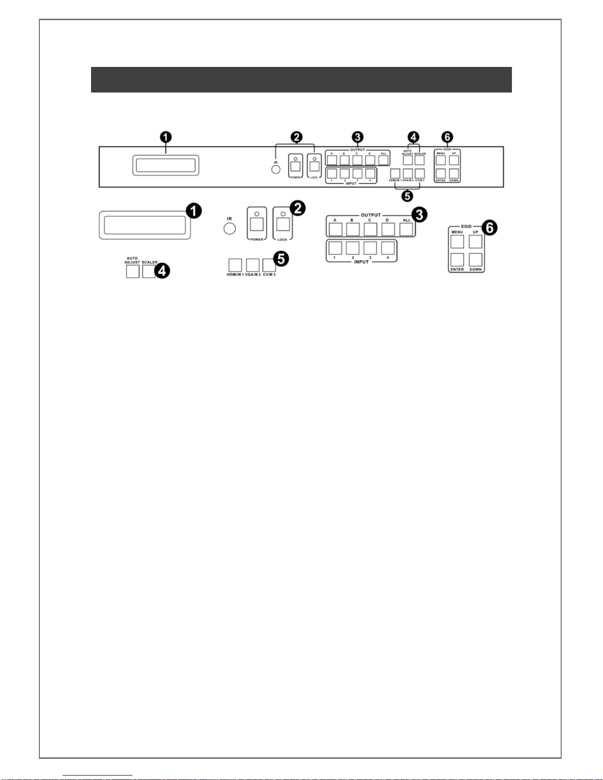
3CHASSIS PANEL DESCRIPTION
Front Panel
1. LCD DISPLAY –Displays system information to the user
2. SYSTEM CONTROLS
a. IR Receiver –Accept commands from supplied infra-red handset
b. Power Button –Place or remove system from standby with LED indicator
c. Lock Button –Front panel control lock with LED indicator
3. INPUT AND OUTPUT SELECTION BUTTONS
4. IMAGE CONTROLS –Buttons to auto adjust RGBHV inputs and resolution scaling control
5. MODE and INPUT VIDEO TYPE SELECTION BUTTONS
6. EDID MENU AND GENERAL NAVIGATION BUTTONS

SDS-2500 USER MANUAL V1.0
© 2018 Smart-e (UK) Ltd
www.smart-e.co.uk
PAGE | 7
Rear Panel
1. BI-DIRECTIONAL INFRA-RED CONNECTORS
2. ANALOGUE VIDEO INPUTS –4x HD15 for RGBHV, 4x Single Phono for composite video and 4x
3.5mm stereo jacks for stereo audio
3. REMOTE CONTROL INTERFACE –1x D9 for RS232 and 1x RJ45 for TCP/IP
4. HDMI OUTPUTS
5. HDMI INPUTS
6. LOCKING DC POWER JACK –Connection for provided external 12V power supply
SDS-2500 USER MANUAL V1.0
© 2018 Smart-e (UK) Ltd
www.smart-e.co.uk
PAGE | 8
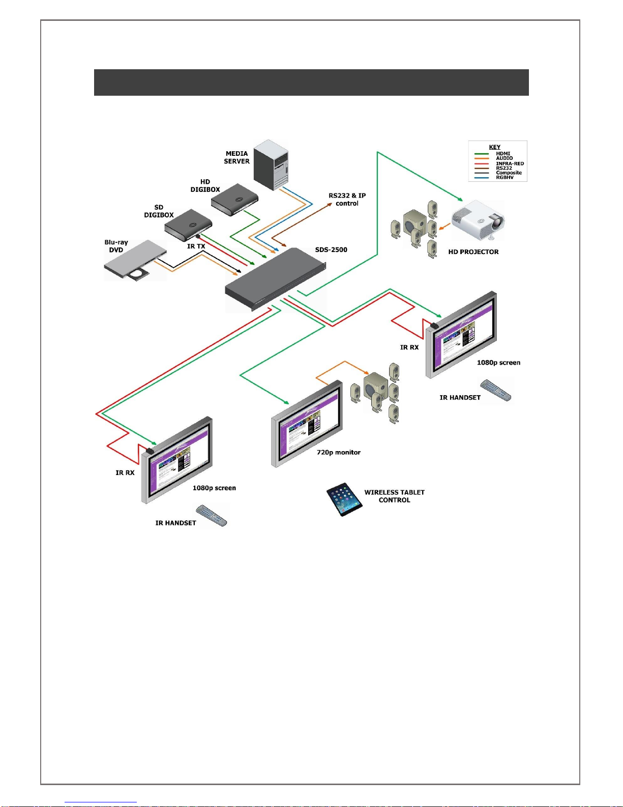
4APPLICATION DIAGRAM
4.1 4X4 MATRIX APPLICATION

SDS-2500 USER MANUAL V1.0
© 2018 Smart-e (UK) Ltd
www.smart-e.co.uk
PAGE | 9
4.2 2X2 VIDEO WALL APPLICATION
SDS-2500 USER MANUAL V1.0
© 2018 Smart-e (UK) Ltd
www.smart-e.co.uk
PAGE | 10
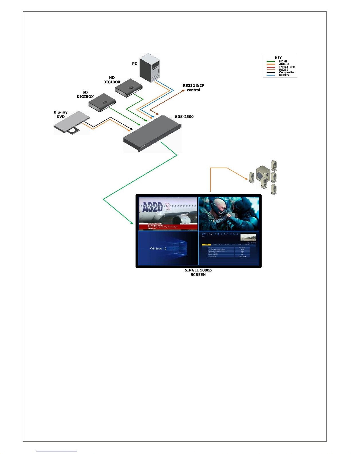
4.3 QUAD-SPLIT POP/PIP APPLICATION

SDS-2500 USER MANUAL V1.0
© 2018 Smart-e (UK) Ltd
www.smart-e.co.uk
PAGE | 11
5REMOTE CONTROL INTERFACES
5.1 RS232 SERIAL CONTROL PORT INTERFACE
PIN
Function
PIN
FUNCTION
1
Not Used
6
Not Used
2
RS232 send data
7
Not Used
3
RS232 receive data
8
Not Used
4
Not Used
9
Not Used
5
Ground Earth
10
Not Used
5.2 TCP/IP CONTROL PORT INTERFACE
5.2.1 TCP/IP CONNECTION VIA SWITCH
Utilise a standard CatX twisted pair patch cable between the TCP/IP control port and a network switch.
Both ends of the patch cable should be terminated to EIA/TIA 568B standard:
EIA/TIA 568B Standard Linear Order
PIN 1
PIN 2
PIN 3
PIN 4
PIN 5
PIN 6
PIN 7
PIN 8
White/Orange
Orange
White/Green
Blue
White/Blue
Green
White/Brown
Brown
5.2.2 TCP/IP CONNECTION DIRECT VIA CROSS-CONNECT
Utilise a “cross-connect” CatX twisted pair patch cable between the TCP/IP control port and the Ethernet
LAN port on a computer.
One end of the patch cable should be terminated to EIA/TIA 568B standard:
EIA/TIA 568B Standard Linear Order
PIN 1
PIN 2
PIN 3
PIN 4
PIN 5
PIN 6
PIN 7
PIN 8
White/Orange
Orange
White/Green
Blue
White/Blue
Green
White/Brown
Brown
One end of the patch cable should be terminated to EIA/TIA 568A standard:
EIA/TIA 568A Standard Linear Order
PIN 1
PIN 2
PIN 3
PIN 4
PIN 5
PIN 6
PIN 7
PIN 8
White/Green
Green
White/Orange
Blue
White/Blue
Orange
White/Brown
Brown
SDS-2500 USER MANUAL V1.0
© 2018 Smart-e (UK) Ltd
www.smart-e.co.uk
PAGE | 12
6INITIAL SETUP
6.1 INSTALLATION
NOTE: Please be aware of the atmospheric conditions outlined later in this manual and ensure that
location chosen for the installation of your SDS-2500 meets these requirements. Do not install in an
environment with excessive dust levels and ensure area is well ventilated.
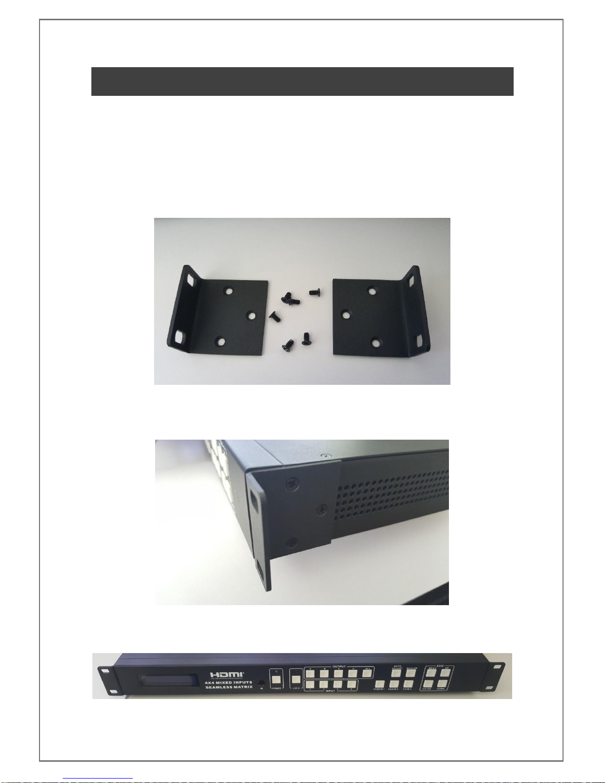
Two options for installation are available, the first of which is for the SDS-2500 to be mounted in a 19” rack
mounting solution. 2x rack mounting ears are provided in the packaging for the SDS-2500 along with 6x
counter-sunk screws.
Using a Philips head screwdriver attach the ears to the pre-drilled locations on the sides of the matrix. Do not
over tighten the screws or they may be damaged.
Once both mounting ears have been fitted to the SDS-2500 the unit can be attached to your 19” rack mounting
solution. Screws for mounting to your 19” rack are not supplied with the SDS-2500, these should be sourced
from the manufacturer of the rack solution.
SDS-2500 USER MANUAL V1.0
© 2018 Smart-e (UK) Ltd
www.smart-e.co.uk
PAGE | 13
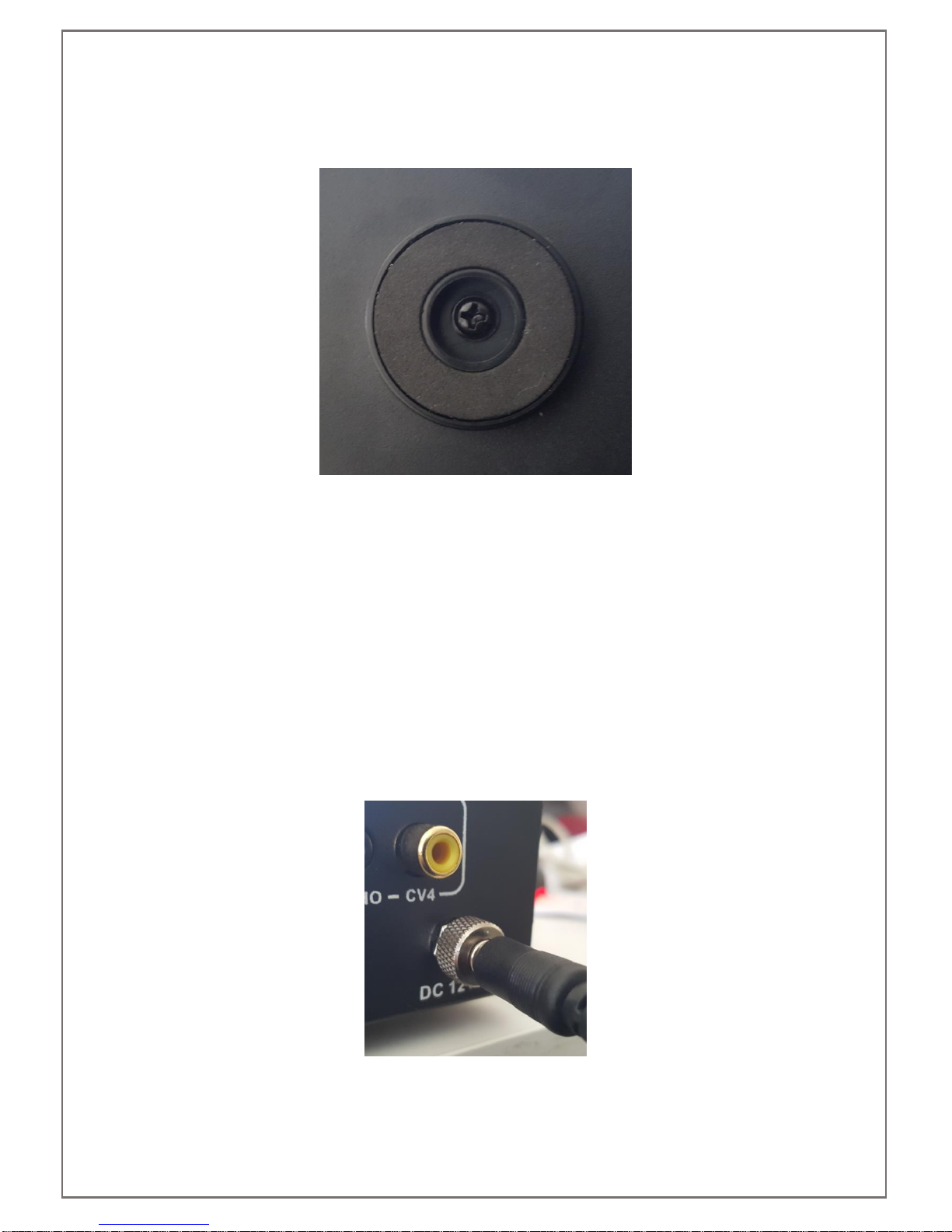
The other option is to use the 4 rubber mounting feet. These come fitted to the SDS-2500 out of the box. They
have a soft underside so can be used on any surface but please ensure the unit is kept level during operation
to ensure good airflow through the ventilation panels on the side of the SDS-2500.
Each rubber foot is held in place with a pan head screw, these can be removed using a Philips head screwdriver
if desired.
6.2 SIGNAL CONNECTIONS
All of the input and output connections are located on the rear of the SDS-2500. For a more detailed
breakdown of these connections refer to section 3 of this manual.
Firstly connect all of the video inputs and outputs required. It is ok to connect multiple mixed format inputs to
the unit at the same time, for instance you could connect active HDMI, VGA, composite and stereo audio inputs
to their respective connectors. Refer to the latter sections of this manual to see how to then switch between
them during operation.
Next connect all of the required PC Control and/or infra-red connections.
Once all of these connections have been made you may attach the provided 12V plug top power supply. Firstly
attach the screw lock terminal. Finger tighten the screw lock, do not over tighten.
Once safely connected the mains adapter side of the power supply can be attached to a mains socket. Please
take note of the input voltage range as detailed on the power supplies label, this can vary by region.
SDS-2500 USER MANUAL V1.0
© 2018 Smart-e (UK) Ltd
www.smart-e.co.uk
PAGE | 14
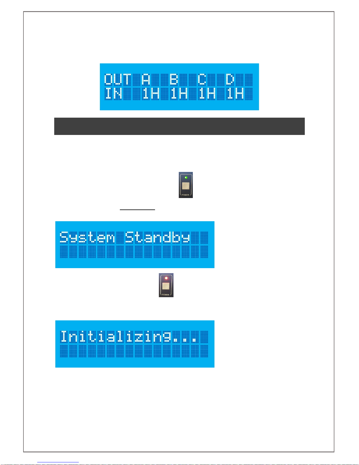
When first powered the unit will be in mode 1, otherwise known as matrix mode and all outputs, A to D, will be
set to video input 1, with all inputs set to HDMI video format. This will be shown on the LCD screen as shown
below.
7FRONT PANEL OPERATION
7.1 SYSTEM CONTROLS
7.1.1 POWER
When the system is on the power LED will be lit green
To place the unit in standby press and hold the power button for 3 seconds, the LCD will update to show as
below before a blank screen is shown
When in standby the power LED will be lit red
To turn the unit back on press the power button and release, the screen will show the initialization screen
before returning to the state it was in prior to entering standby
SDS-2500 USER MANUAL V1.0
© 2018 Smart-e (UK) Ltd
www.smart-e.co.uk
PAGE | 15
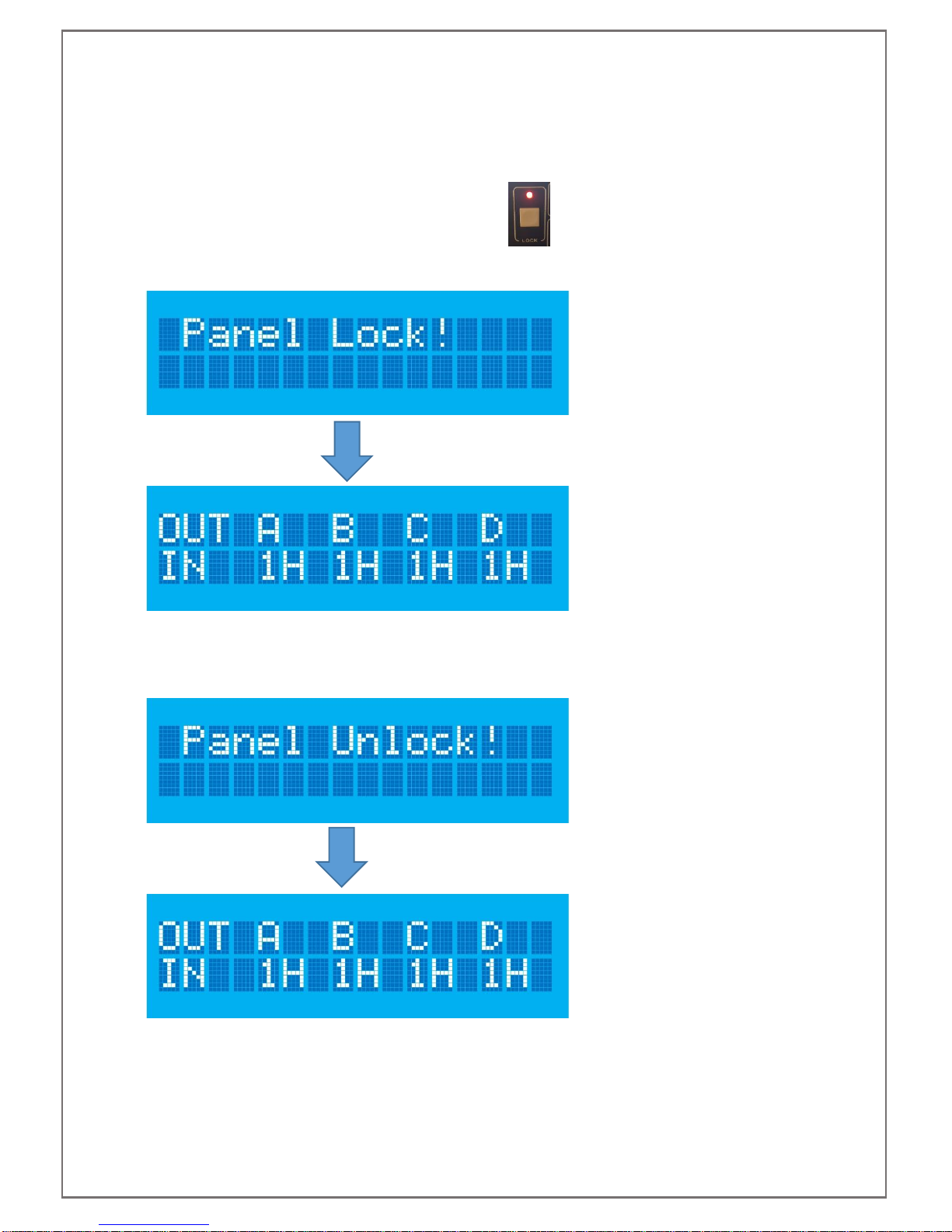
7.1.2 SYSTEM LOCK
The system lock button enables the user to disable all of the front panel controls to avoid any inadvertent
change in settings.
Press and release the lock button, the lock LED will light red
The LCD will show the panel lock notification for 5 seconds before returning to its previous state
5 seconds
To unlock the front panel, press and release the lock button, the led will no longer be illuminated and the LCD
display will show the panel unlock notification for 5 seconds before returning to previous state
5 seconds

SDS-2500 USER MANUAL V1.0
© 2018 Smart-e (UK) Ltd
www.smart-e.co.uk
PAGE | 16
7.2 MODE SELECTION
Three buttons are available on the front of the SDS-2500 to select between the different modes; Matrix,
PIP/POP and video wall.
M1 –Matrix Mode
M2 –PIP/POP Mode
M3 –Video Wall Mode
To Select Matrix Mode press the M1 button. The screen will then update to show as below.
This screen will be displayed for five seconds, within this time you must press the Enter button, located in the
EDID section of the front panel. If pressed within five seconds the SDS-2500 will switch to matrix mode and a
confirmation of the change will appear as below.
If the Enter button is not pressed within five seconds the LCD will return to previous state.
The same process as above can be repeated to select either of the remaining modes by first pressing their
relevant mode button.
SDS-2500 USER MANUAL V1.0
© 2018 Smart-e (UK) Ltd
www.smart-e.co.uk
PAGE | 17
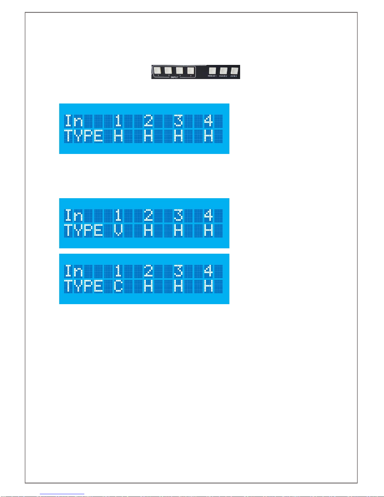
7.3 VIDEO FORMAT SELECTION
The video format selection can be controlled on the front panel of the SDS-2500 by using the four input buttons
and the three mode selection buttons.
Firstly, press the input for which you wish to change the video input format. The screen will update to show the
video selection menu.
The top line shows the four inputs of the SDS-2500, the input button which has been pressed will be reflected
on the screen as that number will be flashing. This screen will be displayed for five seconds with no further
input from the user before returning to the previous state. Within this five seconds you should press the video
format button desired. Below examples show input 1 being changed to VGA, shown as V on the display, and
then to Composite (CV), shown as C on the display.
Once input format(s) has been selected, do not press any front panel buttons for five seconds and the screen
will return to its previous state
SDS-2500 USER MANUAL V1.0
© 2018 Smart-e (UK) Ltd
www.smart-e.co.uk
PAGE | 18
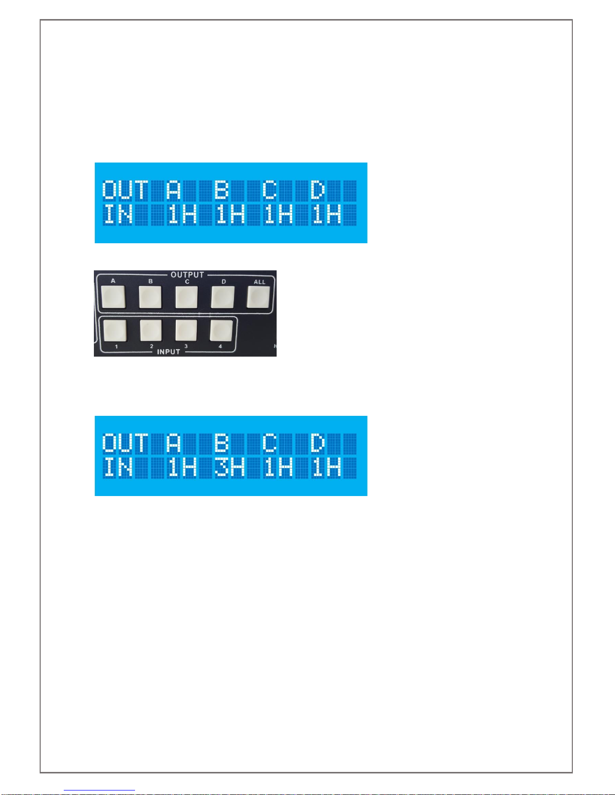
7.4 CROSSPOINT SELECTION
The front panel of the SDS-2500 can be used to change the crosspoint selections, this is only applicable when
the unit is in matrix mode. For control when in other modes please refer to Infra-Red or RS232 control sections
of this manual.
When in matrix mode the LCDs default display will show the 4 outputs, A-D along the top of the display and the
4 inputs they are currently switched to along the bottom of the display.
Changing inputs requires the use of the output and input buttons on the front of the SDS-2500.
To initiate a crosspoint change, press one of the output buttons. As an example we will change output B to
input 3. Firstly, press Output B button, B will flash on the LCD to show that output is now being controlled. The
output selected will continue to flash for five seconds, within this time you should press the input you wish to
switch to, in this example input 3. The LCD will then update to reflect the change.
The remaining outputs can be controlled in a similar fashion when a single crosspoint change is required.
If you wish to switch all four outputs to the same input you can utilise the ALL button. Press this button and all
four outputs A-D will flash for five seconds. Within this time you should press the input to which you want all
outputs switched. The LCD will update to show the change has been successful.
SDS-2500 USER MANUAL V1.0
© 2018 Smart-e (UK) Ltd
www.smart-e.co.uk
PAGE | 19
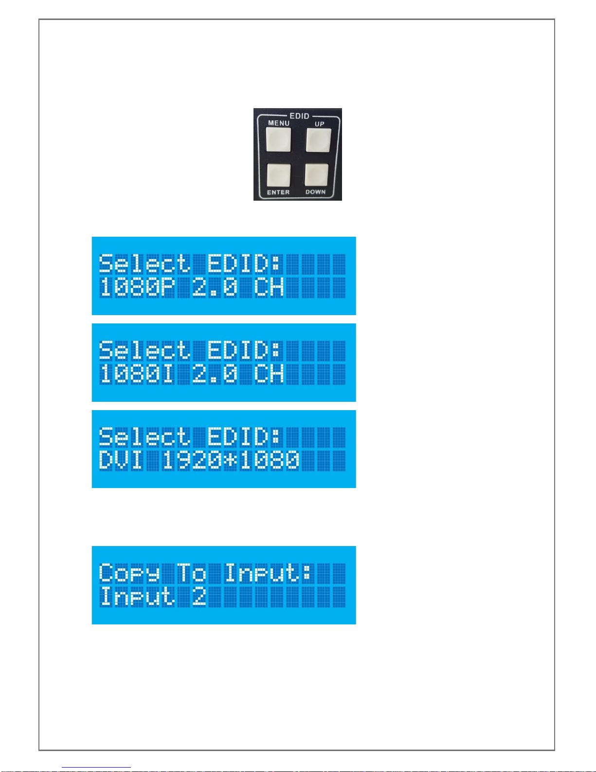
7.5 EDID SETTINGS
The EDID settings of the SDS-2500 can be controlled via the four EDID buttons to the front right of the unit.
To change EDID settings firstly press the MENU button, the LCD will update to show one of the three EDID
options as shown below, the options can be navigated through using the UP and DOWN buttons.
Once the desired EDID is seen on the LCD display press the ENTER key. The LCD will update to ask the user
which inputs they would like the EDID copied to. You may copy the EDID to a single input or to all, navigate
through the options using the UP and DOWN buttons. There is also the option to copy the selected EDID to all
inputs.

SDS-2500 USER MANUAL V1.0
© 2018 Smart-e (UK) Ltd
www.smart-e.co.uk
PAGE | 20
Once the correct input(s) is shown on the LCD press the ENTER button, the screen will briefly show a holding
screen:
Before updating to show the EDID has been read correctly:
For more detailed EDID settings please refer to the RS232 control protocol and RS232 section of this manual.
Table of contents
Popular Media Converter manuals by other brands


Allied Telesis
Allied Telesis AT-PB1000 Series Quick install guide

TR-Electronic
TR-Electronic LMRS-34 user manual

Kramer
Kramer KDS-EN7 user manual

Allied Telesis
Allied Telesis AT-FS201 Series installation guide

Cimarron
Cimarron C25 Service and installation manual

Siemens
Siemens SINAMICS G150 operating instructions


