manuals.online logo
Brands
  1. Home
  2. •
  3. Brands
  4. •
  5. Allied Telesis
  6. •
  7. Media Converter
  8. •
  9. Allied Telesis AT-PB1000 Series User manual

Allied Telesis AT-PB1000 Series User manual

Technical Specifications
Maximum Operating Temperature: 0° C to 40° C (32° F to 104° F)
Maximum Storage Temperature: -25° C to 70° C (-13° F to 15 ° F)
Operating Altitude: Up to 3,04 meters (10,000 feet)
Humidity: 5% to 95% (non-condensing)
EMI/RFI: FCC Class A, EN55022 Class A,
EN61000-3-2, EN61000-3-3
Safety: UL 1950 (UL/cUL), EN60950, EN60 25
Immunity: EN55024 Immunity Standard
Electrical Safety and Emission Statement
Standards: This product meets the following standards.
RFI Emission EN55022 Class A, EN61000-3-2, EN61000-3-3
WARNING: In a domestic environment this product may cause radio interference in which case the user may be required to take
adequate measures.
Immunity EN55024
Electrical Safety TUV-EN60950, UL1950 (UL/cUL)
Laser EN60825
Copyright  2000 Allied Telesyn International, Corp.
All rights reserved. No part of this publication may be reproduced without prior written permission from Allied
Telesyn International, Corp.
Allied Telesyn International Corp.
960 Stewart Drive, Suite B
Sunnyvale, CA 940 5 USA
Tel 1 (40 ) 730-0950 • Fax 1 (40 ) 736-0100
Visit our web site at: www.alliedtelesyn.co
e
U.S. Federal Communications Commission
RADIATED ENERGY
Note: This equipment has been tested and found tocomply with the limits for a Class A digital device pursuant to Part 15 of FCC
Rules. These limits are designed to provide reasonable protection against harmful interference when the equipment is operated in a
commercial environment. This equipment generates, uses, and can radiate radio frequency energy and, if not installed and used in
accordance with this instruction manual, may cause harmful interference to radio communications. Operation of this equipment in a
residential area is likely to cause harmful interference in which case the user will be required to correct the interference at his own
expense.
Note: Modifications or changes not expressly approved of by the manufacturer or the FCC, can void your right to operate this
equipment.
Industry Canada
This Class A digital apparatus meets all requirements ofthe Canadian Interference-Causing Equipment Regulations.
Cet appareil numérique de la classe A respecte toutes les exigences du Règlement sur le matériel brouilleur du Canada.
Overview
The AT-PB1000 Series Gigabit Media Converter is designed for the PowerBlade
Chassis. This media converter extends the distance of your network by converting
Ethernet data between multimode and single-mode fiber optic cable. The media
converters feature a 1000Base-SX port and a 1000Base-LX port. The 1000Base-SX port
has a maximum operating distance of 550 meters (1, 04 feet) while the 1000Base-LX
port has a maximum operating distance of 10 kilometers (6.2 miles) up to 70 kilometers
(43.4 feet) depending on the model. Both ports feature an SC connector and operate at
1000 Mpbs in half-duplex or full-duplex mode.
Related Documents
This quick install guide is an abbreviated version of the installation procedure. For
complete details on the features, functions and installation instructions, refer to the
PowerBlade Chassis Installation Guide. This guide is available from Allied Telesyn’s
web site at www.alliedtelesyn.com.
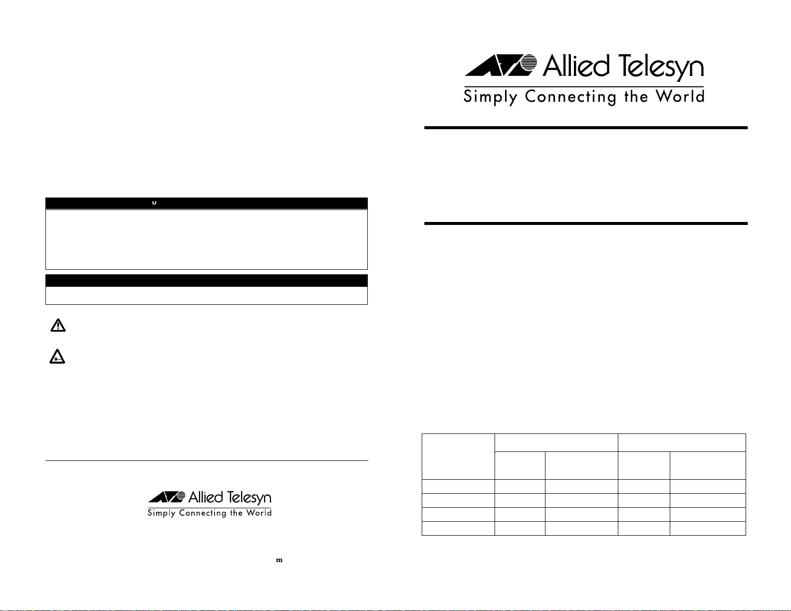
Cable Specifications
The following table lists the cabling distances for the AT-PB1000 Series modules.
Model
1000Base-LX 1000Base-SX
Type of
Connector Maximum
Distance1
1. Assumes 10/125 micron single-mode fiber optic cable.
Type of
Connector Maximum
Distance2
2. Assumes 50/125 micron multimode fiber optic cable.
AT-PB1001/1 SC 10 km (6.2 mi) SC 550 m (1,804 ft)
AT-PB1001/2 SC 20 km (12.4 mi) SC 550 m (1,804 ft)
AT-PB1001/3 SC 50 km (31 mi) SC 550 m (1,804 ft)
AT-PB1001/4 SC 70 km (43.4 mi) SC 550 m (1,804 ft)
3PN 613-50149-00 Rev A 010213
AT-PB1000 Series
Gigabit Media Converters
Quick Install Guide
For use with the PowerBlade Chassis
The following table lists the IEEE 02.3u cabling specifications for the AT-PB1000
Series modules when operating in full-duplex mode.
Cabling specifications for half-duplex operation can be found in the PowerBlade Chassis
Installation Guide.
Package Contents
Make sure the following items are included in your package. If any of these items are
missing or damaged, contact your Allied Telesyn sales representative.
❑One AT-PB1000 Series Gigabit Media Converter
❑This quick install guide
❑Warranty card
Installing the Media Converter
1. Remove a blank faceplate from an empty expansion slot on the front of the chassis.
The module can be installed in any slot.
2. Remove the module from the shipping package and store the packaging in a safe
place. Be sure to observe standard ESD precautions.
3. Slide the module into the expansion slot, aligning it with the guiderails, until it
firmly connects to the chassis’ backplane.
4. Secure the module to the chassis by tightening the thumbscrew.
5. Verify that the PR LED on the front of the module is green.
6. Set the ML/LT switch to the LT (Link Test) position.
7. Set the LT BB/LT SA button to either back to back or standalone, depending on your
topology. Refer to the PowerBlade Chassis Installation Guide for additional
information.
. Remove the dust covers from the fiber optic connectors and connect the data cables.
9. Power ON the end nodes.
Note
End stations used with the media converter must operate with the same duplex
mode (either both full-duplex or both half-duplex mode).
10. Check that the LK LEDs on both ports on the media converter are green. If the
LEDs are OFF, refer to the PowerBlade Chassis Installation Guide for
troubleshooting instructions.
11. If the link test is successful, set the ML/LT switch to the ML (MissingLink) position.
The ML LED should be green. The media converter will not pass network traffic
when a link test is being performed.
12. Repeat this procedure to install additional AT-PB1000 Series modules.
Status LEDs
Fiber Optic Port Specifications
Port Cable Type Maximum Distance
1000Base-SX
All Models 62.5/125 µm multimode fiber 275 m (902 ft)
50/125 µm multimode fiber 550 m (1,804 ft)
1000Base-LX
AT-PB1001/1 62.5/12 5µm multimode fiber 550 m (1,804 ft)
50/12 5µm multimode fiber 550 m (1,804 ft)
10/125 µm single-mode fiber 10,000 m (32,800 ft)
AT-PB1001/2 10/125 µm single-mode fiber 20 km (12.4 mi)
AT-PB1001/3 10/125 µm single-mode fiber 50 km (31 mi)
AT-PB1001/4 10/125 µm single-mode fiber 70 km (43.4 mi)
LED Color Description
System LEDs
PR Green Power is applied to the media converter.
ML Green
OFF
The MissingLink feature is activated.
The MissingLink feature is disabled and the media converter is operating in
the link test mode.
Port LEDs
LK Green A link has been established on the port.
Port Cable Transmitter
OutputPower
(dBm avg.)
Wavelength
(nm)
Minimum
Receiver
Sensivity
(dBm avg.)
1000Base-SX
All Models 50/125 or 62.5/125 micron
multimode -9.5 to -4.0 850 -17.0
1000Base-LX
AT-PB1001 10/125 micron single-mode -9.5 to -3.0 1310 -20.0
50/125 or 62.5/125 micron
multimode -11.5 to -3.0 1310 -20.0
AT-PB1001/2 10/125 micron single-mode -3.0 to 0.0 1310 -24.0
AT-PB1001/3 10/125 micron single-mode -5.0 to 0.0 1550 -24.0
AT-PB1001/4 10/125 micron single-mode 0.0 to 5.0 1550 -24.0
1 2

This manual suits for next models

4

Other Allied Telesis Media Converter manuals

Allied Telesis AT-MC13 User manual

Allied Telesis

Allied Telesis AT-MC13 User manual

Allied Telesis AT-LMC100SC User manual

Allied Telesis

Allied Telesis AT-LMC100SC User manual

Allied Telesis AT-9924SP User manual

Allied Telesis

Allied Telesis AT-9924SP User manual

Allied Telesis Converteon AT-CV5000 User manual

Allied Telesis

Allied Telesis Converteon AT-CV5000 User manual

Allied Telesis Converteon AT-CV1203 User manual

Allied Telesis

Allied Telesis Converteon AT-CV1203 User manual

Allied Telesis AT-GS2002 Series User manual

Allied Telesis

Allied Telesis AT-GS2002 Series User manual

Allied Telesis AT-MC13 User manual

Allied Telesis

Allied Telesis AT-MC13 User manual

Allied Telesis AT-MC101XL User manual

Allied Telesis

Allied Telesis AT-MC101XL User manual

Allied Telesis CentreCOM AT-MC12T User manual

Allied Telesis

Allied Telesis CentreCOM AT-MC12T User manual

Allied Telesis AT-MC1008/GB User manual

Allied Telesis

Allied Telesis AT-MC1008/GB User manual

Allied Telesis MMC2000/200 Series User manual

Allied Telesis

Allied Telesis MMC2000/200 Series User manual

Allied Telesis AT-MC105XL User manual

Allied Telesis

Allied Telesis AT-MC105XL User manual

Allied Telesis UMC2000 Series User manual

Allied Telesis

Allied Telesis UMC2000 Series User manual

Allied Telesis AT-MC1004 User manual

Allied Telesis

Allied Telesis AT-MC1004 User manual

Allied Telesis AT-MC115XL User manual

Allied Telesis

Allied Telesis AT-MC115XL User manual

Allied Telesis AT-MMC6005 User manual

Allied Telesis

Allied Telesis AT-MMC6005 User manual

Allied Telesis AT-G8T User manual

Allied Telesis

Allied Telesis AT-G8T User manual

Allied Telesis AT-G8LX10 User manual

Allied Telesis

Allied Telesis AT-G8LX10 User manual

Allied Telesis AT-DMC1000/SC User manual

Allied Telesis

Allied Telesis AT-DMC1000/SC User manual

Allied Telesis AT-MC605 User manual

Allied Telesis

Allied Telesis AT-MC605 User manual

Allied Telesis Converteon AT-CV5M02 User manual

Allied Telesis

Allied Telesis Converteon AT-CV5M02 User manual

Allied Telesis AT-IMC100T/SCSM User manual

Allied Telesis

Allied Telesis AT-IMC100T/SCSM User manual

Allied Telesis AT-PB10 Series User manual

Allied Telesis

Allied Telesis AT-PB10 Series User manual

Allied Telesis CONVERTEON AT-CM2K0S User manual

Allied Telesis

Allied Telesis CONVERTEON AT-CM2K0S User manual

Popular Media Converter manuals by other brands

Perle C-110-XXXXX installation guide

Perle

Perle C-110-XXXXX installation guide

Transition Networks M/E-PSW-FX-01SC user guide

Transition Networks

Transition Networks M/E-PSW-FX-01SC user guide

Orbis ATC-810 user manual

Orbis

Orbis ATC-810 user manual

Schumacher Electric BATTERY EXTENDER BE01256 owner's manual

Schumacher Electric

Schumacher Electric BATTERY EXTENDER BE01256 owner's manual

Polytron QAM 12 LAN manual

Polytron

Polytron QAM 12 LAN manual

VigilLink VL-DA2PE-1 user manual

VigilLink

VigilLink VL-DA2PE-1 user manual

Goobay SPW MW 1P100FV user manual

Goobay

Goobay SPW MW 1P100FV user manual

CYP CLUX-18CEC Operation manual

CYP

CYP CLUX-18CEC Operation manual

Wacker Neuson FUH35 Operator's manual

Wacker Neuson

Wacker Neuson FUH35 Operator's manual

opticis OMVC-200 user manual

opticis

opticis OMVC-200 user manual

ADF Web HD67235-A1 user manual

ADF Web

ADF Web HD67235-A1 user manual

Televes TOX Series Quick installation guide

Televes

Televes TOX Series Quick installation guide

Moog Videolarm EOF2N Installation and operation instructions

Moog Videolarm

Moog Videolarm EOF2N Installation and operation instructions

DJ-Tech cd encoder 10 user manual

DJ-Tech

DJ-Tech cd encoder 10 user manual

Precision Digital Corporation PROVU PDA1232 instruction manual

Precision Digital Corporation

Precision Digital Corporation PROVU PDA1232 instruction manual

Moxa Technologies VPort 451 user manual

Moxa Technologies

Moxa Technologies VPort 451 user manual

Sony DVMC-DA2 Specifications

Sony

Sony DVMC-DA2 Specifications

CYP DCT-1 Operation manual

CYP

CYP DCT-1 Operation manual

manuals.online logo
manuals.online logoBrands
  • About & Mission
  • Contact us
  • Privacy Policy
  • Terms and Conditions

Copyright 2025 Manuals.Online. All Rights Reserved.