Smartgen BAC150CAN User manual

BAC150CAN
BATTERY CHARGER
USER MANUAL
SMARTGEN (ZHENGZHOU) TECHNOLOGY CO., LTD
Chinese trademark
English trademark
SmartGen —make your generator smart
SmartGen Technology Co., Ltd.
No.28 Jinsuo Road
Zhengzhou
Henan Province
P. R. China
Tel: 0086-371-67988888/67981888
0086-371-67991553/67992951
0086-371-67981000(overseas)
Fax: 0086-371-67992952
Web: http://www.smartgen.com.cn
http://www.smartgen.cn
Email: sales@smartgen.cn
All rights reserved. No part of this publication may be reproduced in any material form (including
photocopying or storing in any medium by electronic means or other) without the written permission of
the copyright holder.
Applications for the copyright holder’s written permission to reproduce any part of this publication should
be addressed to Smartgen Technology at the address above.
Any reference to trademarked product names used within this publication is owned by their respective
companies.
Smartgen Technology reserves the right to change the contents of this document without prior notice.
Table 1 Software Version
Date
Version
Note
2019-03-05
1.0
Original Release

BAC150CAN Battery Charger User Manual
BAC150CAN Battery Charger Version 1.0 2019-03-05 Page 3 of 13
CONTENT
1OVERVIEW............................................................................................................................4
2PERFORMANCE AND CHARACTERISTICS.......................................................................4
3CHARGING PRINCIPLE .......................................................................................................5
4PARAMETERS SPECIFICATION..........................................................................................7
5PARAMETERS CONFIGURATION.......................................................................................8
6OPERATION........................................................................................................................11
7CONNECTION.....................................................................................................................12
8CASE DIMENSIONS ...........................................................................................................13

BAC150CAN Battery Charger User Manual
BAC150CAN Battery Charger Version 1.0 2019-03-05 Page 4 of 13
1 OVERVIEW
BAC150CAN is a kind of battery charger with intelligent multi-functions, which is specially
designed for genset lead-acid battery to meet the charging characteristics. It is suitable for 12V/24V
battery with maximum10A output current.
2 PERFORMANCE AND CHARACTERISTICS
BAC150CAN has the following characteristics:
1) Switch power supply structure, wide high voltage input, small size, light weight, high efficiency;
2) It can work automatically by the method of two-stage or three-stage as required. The two
methods both are designed according to battery charging characteristics, and can prevent
lead-acid battery overcharging, which extremely improves the battery life span;
3) Built-in PFC is designed, so when the output terminal is connected reversely, it shall be AC power
supply, which can effectively protect the charger. When the reverse connection is removed, it
shall recover the output automatically;
4) Multi-function output port is designed, and it can be configured on PC. Low output level is active.
5) Multi-function input port is designed, and it can be configured on PC. Low input level is active.
6) Temperature sensor port is designed, which can monitor the battery temperature of current time;
and it also has temperature compensation function, which can effectively prevent over high
battery temperature;
7) Standard RS485 serial communication interface, CAN communication interface, and USB
communication interface are designed;
8) LED display: Charging status indicator, and alarm indicator.
BAC150CAN Battery Charger User Manual
BAC150CAN Battery Charger Version 1.0 2019-03-05 Page 5 of 13
3 CHARGING PRINCIPLE
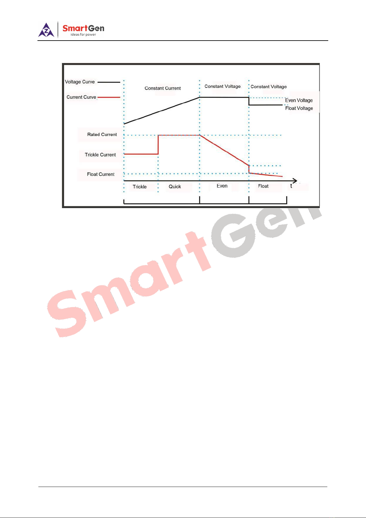
Fig. 1 3-Stage Charging Curve Gragh
Three-stage charging method is applied for the charger to work according to the battery charging
characteristics.
1) The first stage is ‘Constant Current’ mode. When the terminal voltage is comparatively low, the
charging current is small, which effectively prevents the battery from damaging because of high
temperature, calling ‘low voltage trickle charging’. When the terminal voltage gets high, the
charging current changes to rated current, which makes the battery electricity increasing rapidly.
This process is ‘quick charging’.
2) The second stage is ‘Even Charging’mode. After constant current mode, the voltage gets up to
the even voltage value, and at this time the charger keeps constant voltage output. The charging
current slows down, and the terminal voltage also slowly keeps at the value of even voltage.
3) The third stage is ‘Float Charging’mode. After the above two stages, the charging is basically
completed and output voltage of the charger switches to float voltage automatically. Charging
current also drops to float current. All white LED indicators are illuminated always. Afterwards the
charging current only offsets the battery self-discharge and longtime charging is unharmful for the
battery.

BAC150CAN Battery Charger User Manual
BAC150CAN Battery Charger Version 1.0 2019-03-05 Page 6 of 13
Fig. 2 2-Stage Charging Curve Graph
Two-stage charging method is applied for the charger to work according to the battery charging
characteristics.
1) The first stage is ‘Constant Current’ mode. When the terminal voltage is comparatively low, the
charging current is small, which effectively prevents the battery from damaging because of high
temperature. This process is called ‘low voltage trickle charging’. When the terminal voltage gets
high, the charging current changes to rated current, which makes the battery electricity increasing
rapidly. This process is ‘quick charging’.
2) The second stage is ‘Float Charging’mode. As the electricity gets higher and higher, the charging
current is getting smaller. When the current is below 0.5A, the battery is fully charged. Then the
charging current offsets the battery self-discharge and longtime charging is unharmful for the
battery.
BAC150CAN Battery Charger User Manual
BAC150CAN Battery Charger Version 1.0 2019-03-05 Page 7 of 13
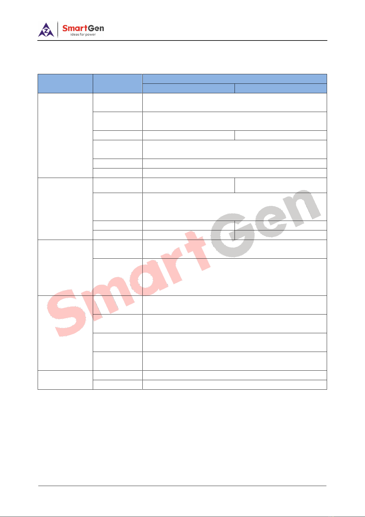
4 PARAMETERS SPECIFICATION
Table 2 Product Parameters
Type
Item
Parameters
12V
24V
Input
Characteristics
Nominal AC
Voltage
AC (100~277)V
Max. AC
Voltage
AC (90~305)V
Max. Current
1.8A
3.5A
No-load Power
Consumption
<3W
AC Frequency
50Hz/60Hz
Efficiency
85%
Output
Characteristics
No-load
Output Voltage
13.5V, Error ±0.2V
27.0V, Error ±0.2V
Rated
Charging
Current
5A, Error ±0.2A
Max. Power
80W
135W
Min. Voltage
3.5V
7V
Insulating
Property
Insulation
Resistance
Between input and output, input and PE, output and PE all are:
RL≥500 MΩ
Insulation
Voltage
Between input and output, input and PE both are: AC3kV 50Hz
1min; leakage current: IL ≦3.5mA
Between output and PE is: AC500V 50Hz 1min; leakage
current: IL ≦3.5mA
Working
Condition
Working
Temperature
(-30~+55)°C
Storage
Temperature
(-40~+85)°C
Working
Humidity
20%RH~93%RH(No condensation)
Storage
Humidity
10%RH~95%RH(No condensation)
Shape Structure
Weight
0.58kg
Dimension
171mm×119.5mm×65.5mm (length*width*height)

BAC150CAN Battery Charger User Manual
BAC150CAN Battery Charger Version 1.0 2019-03-05 Page 8 of 13
5 PARAMETERS CONFIGURATION
Table 3 Parameter Configuration
Items
Default
Adjustable Range
Description
12V
24V
12V
24V
Battery Selection
2
(0~2)
0: 12V
1: 24V
2: Self-adjusted
Charging Method
3
(2~3)
2: Two-stage;
3: Three-stage
Max. Rated Current
5.0A
/
Maximum charging current
Rated Current
100%
(0~100)%
Maximum rated charging current
percentage
Even Charging
Voltage
14.1V
28.2V
(10~16)V
(20~30)V
The charging voltage of “Constant
Voltage”
Even Charging
Enable
1
(0~1)
0: Disable; 1: Enable
Even Charging
Time Setting
1.0h
(0.1~100)h
The charging time of Constant
Voltage
Even Charging
Completion Current
1
(0~1)
0: Disable; 1: Enable
Completion Current
Setting
0.50A
(0.20~3.00)A
The transition current from Even
Charging to Float Chargeing
Float Charge
Voltage
13.5V
27.0V
(10~16)V
(20~30)V
The voltage of “Float Charge”
AUTO BOOST
Voltage
12V
24V
(10~16)V
(20~30)V
When the charger is in Float Mode,
it enters Quick Charge if the battery
voltage has fallen below this value.
AUTO BOOST
Voltage Delay
20s
(0~3600)s
When the battery voltage is below
this value for the delay time, it gets
into BOOST status.
Trickle Charge
0
(0~1)
0: Disable; 1: Enable
Trickle Charge
Voltage
11.0V
22.0V
(10~16)V
(20~30)V
The voltage of Trickle Charge
Trickle Charge
Current
50%
(0~100)%
Maximum rated charging current
percentage
Battery Under
Voltage Warn
1
(0~1)
0: Disable; 1: Enable
Under Voltage Set
Value
11.5V
23.0V
(8~15)V
(16~30)V
Under voltage alarm will be
initiated if the battery voltage has
fallen below the set value.
Under Voltage
Delay
120s
(0~3600)s
Under voltage alarm will be
initiated if the battery voltage has
fallen below the set value and the
delay timer has expired.

BAC150CAN Battery Charger User Manual
BAC150CAN Battery Charger Version 1.0 2019-03-05 Page 9 of 13
Items
Default
Adjustable Range
Description
12V
24V
12V
24V
Under Voltage
Return Value
12.5V
25.0V
(8~15)V
(16~30)V
The transition voltage from ‘under
voltage’ to ‘normal voltage’
Under Voltage
Return Delay
10s
(0~3600)s
Under voltage alarm will be
removed if the battery voltage has
exceeded the return value and the
delay time has expired.
Battery Over
Voltage Warn
1
(0~1)
0: Disable; 1: Enable
Over Voltage Set
Value
16V
32V
(8~16)V
(16~32)V
Over voltage alarm will be initiated
if the battery voltage is above the
set value.
Over Voltage Delay
2s
(0~3600)s
Over voltage alarm will be initiated
if the battery voltage is above the
set value and the delay time has
expired.
Over Voltage
Return Value
15.8V
31.6V
(8~16)V
(16~32)V
The transition voltage from ‘over
voltage’ to ‘normal voltage’
Over Voltage
Return Delay
10s
(0~3600)s
Over voltage alarm will be
removed if the battery voltage is
below the return value and the
delay time has expired.
Temperature
Sensor
1
(0~1)
0: Disable; 1: Enable
Temperature
Compensation
1
(0~1)
0: Disable; 1: Enable
Temperature
Compensation Set
Value
0.018V/℃
0.036V/℃
(0.010~0.
030)V/℃
(0.020~0.
060)V/℃
The Compensation of every 1℃
change on 20℃basis.
High Temp. Warn
1
(0~1)
0: Disable; 1: Enable
High Temp. Set
Value
55℃
(0~80)℃
High Temp. alarm will be initiated
if the battery temperature has
exceeded the set value.
High Temp. Delay
0.5s
(0~60.0)s
High Temp. alarm will be
initiated if the battery
temperature has exceeded the
set value and the delay time
has expired.
High Temp. Return
Value
50℃
(0~80)℃
The transition temperature from
High Temp. to Normal Temp.
High Temp. Return
Delay
1.0s
(0.0~60.0)s
High Temp. alarm will be
removed if the battery
temperature has fallen below
the return value and the delay
time has expired.

BAC150CAN Battery Charger User Manual
BAC150CAN Battery Charger Version 1.0 2019-03-05 Page 10 of 13
Items
Default
Adjustable Range
Description
12V
24V
12V
24V
Auxiliary Input Port
3
(0~5)
0: Not Used;
1: Shutdown; The battery
charger enters Standby Status
if the input is active.
2: Reserved;
3: Manual BOOST:
The battery charger enters
BOOST if the input is active.
4: Return to Float Mode:
The charger enters Float Mode
if the input is active.
5: Rated Voltage Output:
Charger shall output rated
voltage if the input is active.
Auxiliary Input Port
Delay
2.0s
(1.0~60.0)s
The corresponding action will
be active if the input is active
and the delay time has expired.
Auxiliary Output
Port Setting
Charging Failure
Waring
Mains Failure
Warning
Multiple choices are
available.
Not Used;
Output over voltage warning;
Output under voltage warning;
External temp. sensor
short-circuit warning;
Charging failure warning’;
Mains failure warning;
Auxiliary Output
Port Delay
2.0s
(1.0~60.0)s
Output port is active after the
delay time.
Communication
Address
10
1~254
RS485 communication address
RS485 Baud Rate
0
(0~2)
1: stop bit;
0: 9600bps;
1: 19200bps;
2: 38400bps;
CAN Baud Rate
1
(0~2)
0:125kbps;
1: 250kbps;
2: 500kbps;
Battery Type
0
(0~4)
0: Lead-acid;
1: Li Battery;
2: Calcium-Calcium;
3: Power;
4: Users-defined;

BAC150CAN Battery Charger User Manual
BAC150CAN Battery Charger Version 1.0 2019-03-05 Page 11 of 13
6 OPERATION
Fig. 3 BAC150CAN Panel Drawing
Table 4 Connection Description
Terminal
Function
Description
AC Input
Port
L
AC Terminals
Connect terminals L and N to AC (100~240)V;
bigger than BVR 1.5mm2multi-strand copper line
is recommended.
N
PE
GND Terminal
Connect to the ground.
USB Port
USB
USB communication port
Related parameters can be set on PC via USB.
RS485 Port
A(+)
RS485 communication
port
Standard RS485 serial communication port.
B(-)
SCR
Shielding GND Terminal
Connect to B- inside the charger.
CAN Port
H
CAN High
CAN communication port.
L
CAN Low
Auxiliary
Input/Output
Port
IN
Auxiliary Input Port
Active when connect to B- output.
OUT
Auxiliary Output Port
Output B- voltage when active.
Temp.
Sensor Port
BT
Battery Temp. Sensor
Port
Connect to PT1000 sensor externally.
DC Output
Port
B-
Battery Output Negative
Connect to battery negative; bigger than BVR
2.5mm2multi-strand copper line is recommended.
B-
B+
Battery Output Positive
Connect to battery positive; bigger than BVR
2.5mm2multi-strand copper line is recommended.
Charging
Indicator
White
Charging status
indication
When the current is less than 10%, they shall be
illuminated all according to charging voltage and
current indication charging status.
Alarm
Indicator
Red
Alarm status Indication
Over voltage, under voltage, charging failure,
temp. sensor short-circuit, mains failure, temp.
high alarm, BOOST status warning, battery
reverse connection alarm can be configured;
indicator status can be flash, or light. Flash status
default is charging failure, mains failure, battery
reverse connection alarm; light status default is
over voltage, under voltage, temp. sensor
short-circuit, and temp. high warning.
All indication are extinguished when there are not
alarms.
BAC150CAN Battery Charger User Manual
BAC150CAN Battery Charger Version 1.0 2019-03-05 Page 12 of 13
NOTES:
1) Because there are diode and current-limiting circuit inside the charger, it can be used together with charging
generator, and it is needless to disconnect the charger when cranking.
2) When this is applied on the genset, as charging current is very large, it shall produce voltage drop in the charging
wire. So this is recommended that charging wire shall be separately connected to battery terminal, aiming to avoid
disturbance on sampling precision.
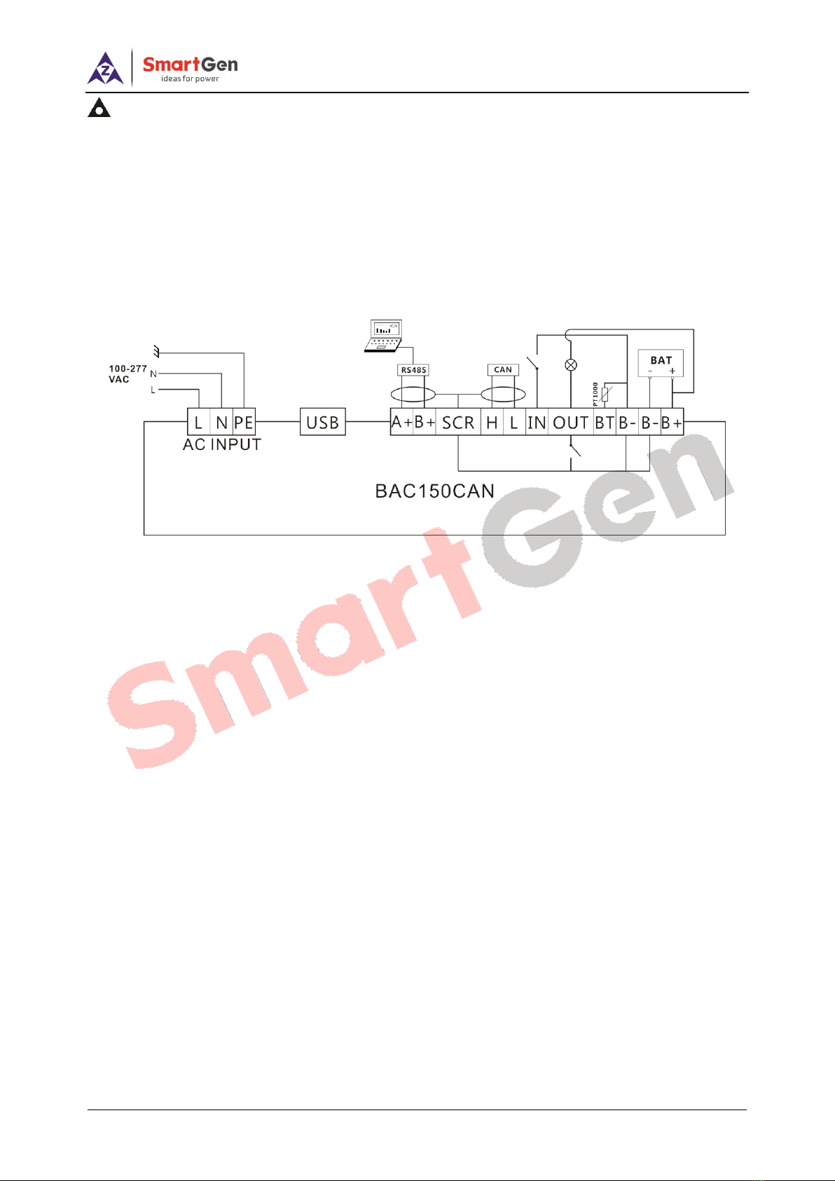
7 CONNECTION
Fig. 4 BAC150CAN Wiring Connection

BAC150CAN Battery Charger User Manual
BAC150CAN Battery Charger Version 1.0 2019-03-05 Page 13 of 13
8 CASE DIMENSIONS
(a) Bolt Mounting
(b) Guide Rail Mounting
Fig. 5 BAC150CAN Mounting Case Dimension
_____________________________________
Unit: mm
Table of contents
Other Smartgen Batteries Charger manuals

Smartgen
Smartgen BAC1205N User manual

Smartgen
Smartgen BAC2410 User manual

Smartgen
Smartgen BAC1203VE User manual

Smartgen
Smartgen BAC1203VL User manual

Smartgen
Smartgen BAC06A User manual

Smartgen
Smartgen BAC4812-KP User manual

Smartgen
Smartgen BAC06AU User manual

Smartgen
Smartgen BAC4812-KP User manual

Smartgen
Smartgen BAC1203 User manual

Smartgen
Smartgen BAC2405 User manual

Smartgen
Smartgen BAC06H User manual

Smartgen
Smartgen BACM2420 User manual

Smartgen
Smartgen BAC06 Series User manual

Smartgen
Smartgen BAC06S User manual

Smartgen
Smartgen BAC4812 User manual

Smartgen
Smartgen BACM2420 User manual

Smartgen
Smartgen BAC2410BST User manual

Smartgen
Smartgen BACMXX06 Series User manual


