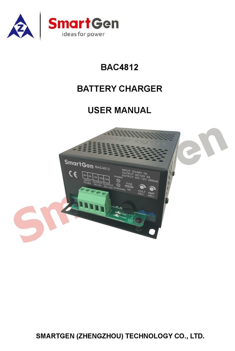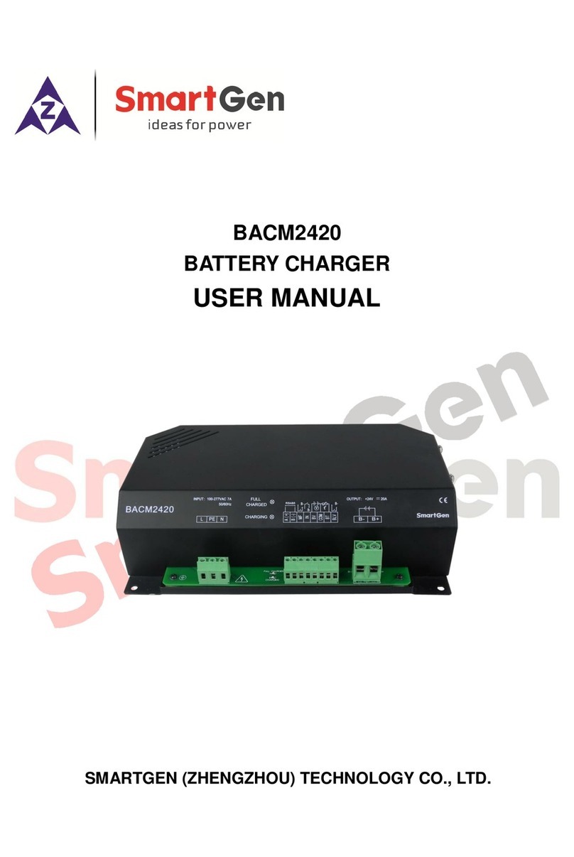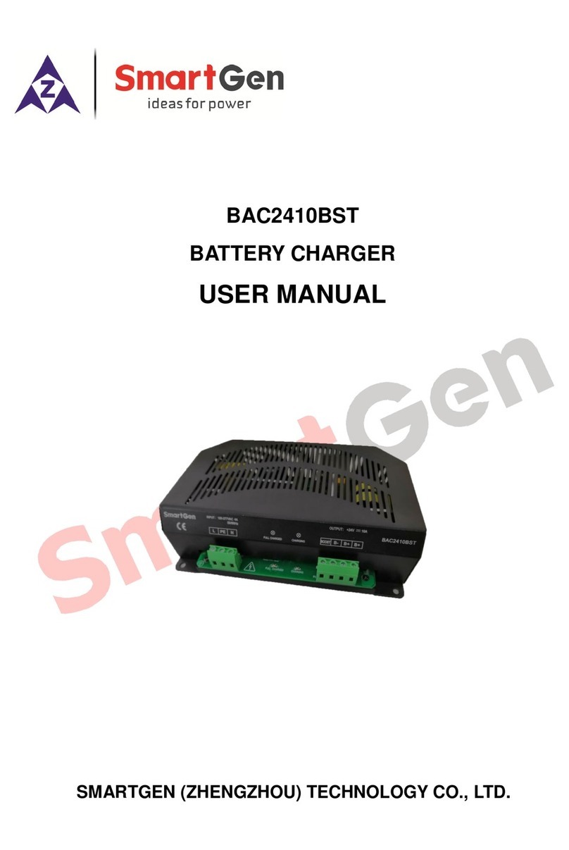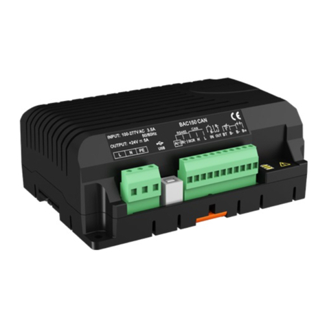
BAC06 Series Switch-type Battery Charger User Manual
BAC06 Series Switch-type Battery Charger Version 1.42017-10-24 Page 6 of 8
6 OPERATION
6.1 BAC06 SERIES PANEL DRAWING DESCRIPTION
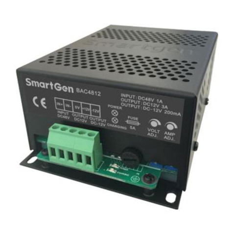
Chart 2. BAC06A
Chart 3. BAC06V
Terminals L and N connect AC 220V, using multi-strand BVR 1mm2copper wires.
Terminals B+ and B- connect battery positive and negative, using multi-strand
BVR1.5mm2copper wires.
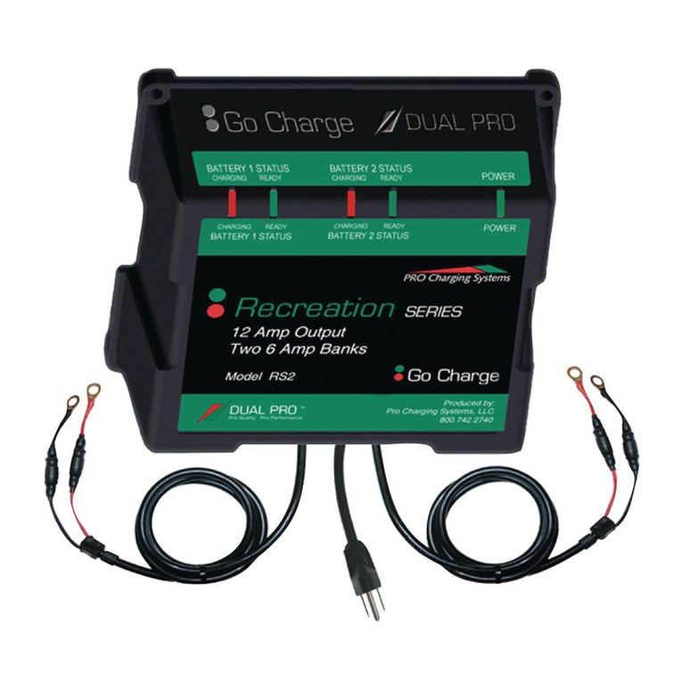
POWER: Power indicator. When charger works, it will illuminate.
CHARGING: Battery charging indicator. When charging current is over 0.3A, it will
illuminate.
VOLT: Voltage adjustment potentiometer.
AMP: Current adjustment potentiometer.
Output 10A fuse. Reverse connection will cause fuse blown. After correcting the connection and
changing another fuse, it can continue working.
Note:
1) Because there is diode and current-limiting circuit inner the charger, it can be used together with
charging generator, and there is no need to disconnect the charger when cranking.
2) During gen-set is running, high current will cause voltage drop in charging line, so recommend
separately connecting to battery terminal to avoid disturbance on sampling precision.
6.2 BAC06 SERIES TROUBLESHOOTING
6.2.1 FAULT DIAGNOSIS
Output terminal of battery charger short circuit or battery reverse connection may blow the charger
output fuse. In that case, after connecting AC power supply, charger green LED lights up but output
terminal without voltage outputting, and then remove the output fuse tube to visually observe whether
fuse is blown or not, if condition permit, multimeter can be used to measure the fuse status.
a) If output terminal 10A fuse is blown, users only need to change the same capacity fuse.
b) If output fuse isn’t blown or battery without outputting after changing the fuse, battery needs to depot
repair.
c) Fuse burn emergency method: using conductive metal wire short connected burnt fuse, and then
change the fuse later.
