Smartgen HRM3300 User manual

HRM3300
Remote Control Module
User Manual
ZHENGZHOU SMARTGEN TECHNOLOGY CO.,LTD

Chinese trademark
English trademark
SmartgGen —make your generator smart
SmartGen Technology Co., Ltd.
No. 28 Jinsuo Road
Zhengzhou City
P. R. China
Tel: +86-371-67988888
+86-371-67981888
+86-371-67991553
+86-371-67992951
+86-371-67981000 (overseas)
Fax: 0086-371-67992952
Web: http://www.smartgen.com.cn/
http://www.smartgen.cn/
Email: [email protected]
All rights reserved. No part of this publication may be reproduced in any material
form (including photocopying or storing in any medium by electronic means or
other) without the written permission of the copyright holder.
Smartgen Technology reserves the right to change the contents of this
document without prior notice.
If the colors of actual products are different from the manual, please take the
actual product as the standard.
Software Version
Date
Version
Content
2013-12-05
1.0
Original release.
2015-03-25
1.1
Modify case dimension.

This manual is suitable for HRM3300 remote control module only.
Clarification of notation used within this publication.
SIGN
INSTRUCTION
NOTE
Highlights an essential element of a procedure to ensure
correctness.
CAUTION!
Indicates a procedure or practice, which, if not strictly
observed, could result in damage or destruction of
equipment.
WARNING!
Indicates a procedure or practice, which could result in injury
to personnel or loss of life if not followed correctly.

CONTENTS
1. OVERVIEW AND FEATURES.................................................. 5
2. SPECIFICATION ...................................................................... 6
3. DISPLAY ..................................................................................7
3.1 PUSHBUTTONS....................................................................7
3.2 LCD DISPLAY ........................................................................8
3.2.1 Main DISPLAY (Home page)............................................8
3.2.2 Data display..................................................................... 8
4. OPERATION............................................................................. 9
4.1 REMOTE START/STOPPROCEDURE..................................9
4.2ACKNOWLEDGE OPERATION........................................................ 9
5. BACK PANEL......................................................................... 10
6. APPLICATION DIAGRAM...................................................... 11
7. INATALLATION ...................................................................... 12

HRM3300 REMOTE CONTROL MODULE USER MANUAL
HRM3300 Remote Control Module 2015-03-25 Version1.1 Page 5 of 9
1.OVERVIEW AND FEATURES
HRM3300 remote control module is a remote control module for HMC9000
controller. With the help of CANBUS it can carry out remote start/stop of the
marine genset, data measurement, alarm display and other functions.
HRM3300 is designed for single generator remote control systems. The module
has monitor mode, in which it only monitors, but does not control the genset. Up
to 16 HRM3300 modules can be connected to one HMC9000 controller.
The module contains 32-bit ARM microprocessor; it is fitted with a large
480*272 resolution TFT-LCD monitor, selectable English/Chinese interface.
The home page of the monitor is instrument display. The brightness of the LCD
monitor and LED light indicators can be adjusted, which enables operation in
different conditions. The module is designed for panel mounting, it has simple
structure, simple connections and can be widely used in various situations.

HRM3300 REMOTE CONTROL MODULE USER MANUAL
HRM3300 Remote Control Module 2015-03-25 Version1.1 Page 6 of 9
2.SPECIFICATION
Items
Content
Operating Voltage
DC18.0V to 35.0V, continuous power supply.
CANBUS Baud rate
125kbps
Max. transmission distance
500m
LCD/LED Brightness
11 Stage adjustable
Total consumption
≤2W
Overall dimension
266mm x 182mm x 45mm
Panel cutout
214mm x 160mm
Shell material
Self extinguishing ABS+PC
Button material
Silicon rubber
Working Conditions
Temperature:(-25~+70)°C
Humidity:(20~93)%RH
Storage Condition
Temperature:(-25~+70)°C
Protection Level
IP55 Gasket
Weight
0.75kg

HRM3300 REMOTE CONTROL MODULE USER MANUAL
HRM3300 Remote Control Module 2015-03-25 Version1.1 Page 7 of 9
3.DISPLAY
3.1 PUSHBUTTONS
Stop
Stop running generator in remote mode;
During stopping process, press this button
again to stop generator immediately.
Start
Start genset in remote mode.
Sound Alarm
Acknowledge
In case of sound alarm pressing this button
will mute the panel buzzer.
Light Alarm
Acknowledge
In case of alarm pressing this button will
return flash indicator to its illuminating
condition.
Lamp Test
Pressing this button will illuminate all the
LED indicators on the panel and highlight
the LCD monitor.
Brightness+
Pressing and holding this button can
increase brightness of LCD monitor and
LED indicators.
Brightness-
Pressing and holding this button can
decrease brightness of LCD monitor and
LED indicators.
Up/Increase
Scroll the screen up.
Down/Decrease
Scroll the screen down.
Left
Scroll the pages left.
Right
Scrolls the pages right.
Homepage
Press this button to return to the home
page;

HRM3300 REMOTE CONTROL MODULE USER MANUAL
HRM3300 Remote Control Module 2015-03-25 Version1.1 Page 8 of 9
In settings menu press this button to save
changes.
Settings
Press this button to enter into settings
screen;
In settings menu press this button to return
to previous menu.
3.2 LCD DISPLAY
Data displayed on the LCD is obtained from HMC9000 via CANBUS port. Press
to switchover between the pages of the monitor. Press to return to the
home page and to enter into parameter configuration pages.
3.2.1 MAIN DISPLAY (HOME PAGE)
The main screen displays engine speed, coolant temperature, oil pressure, two
batteries voltage and engine status. The main screen looks as follows:
3.2.2 DATA DISPLAY
The main screen is divided into two separate viewing areas: left and right.
Left area has only one page and shows diesel engine operation status and
battery status; press to view the right area. Right area is divided into pages:
engine page, alarm page, expansion module data page and event log page etc.
1. Engine page
Displays engine speed, sensors 1-8 values, main battery voltage, standby
battery voltage, charger voltage, GOV output ratio, total run time and total
start times.
For J1939 engines, an additional ECU page will be displayed. ECU data
includes coolant pressure, coolant level, fuel temperature, fuel pressure,
inlet temperature, exhaust temperature, turbo pressure, fuel consumption,

HRM3300 REMOTE CONTROL MODULE USER MANUAL
HRM3300 Remote Control Module 2015-03-25 Version1.1 Page 9 of 9
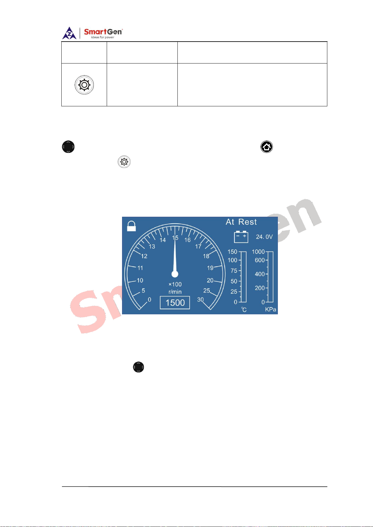
total fuel consumption etc (Different engine with different parameters).
2. Alarm page:
It displays all kinds of warning alarms and shutdown alarms which detected
by controller.
3. Other parameters page
HMC9000 main controller’s date and time, inputs/outputs status.
4. OPERATION
Press and input the password to enter into parameter configuration menu.
Configurable parameters include displayed language, operation mode and
password.
The module has two operation modes:
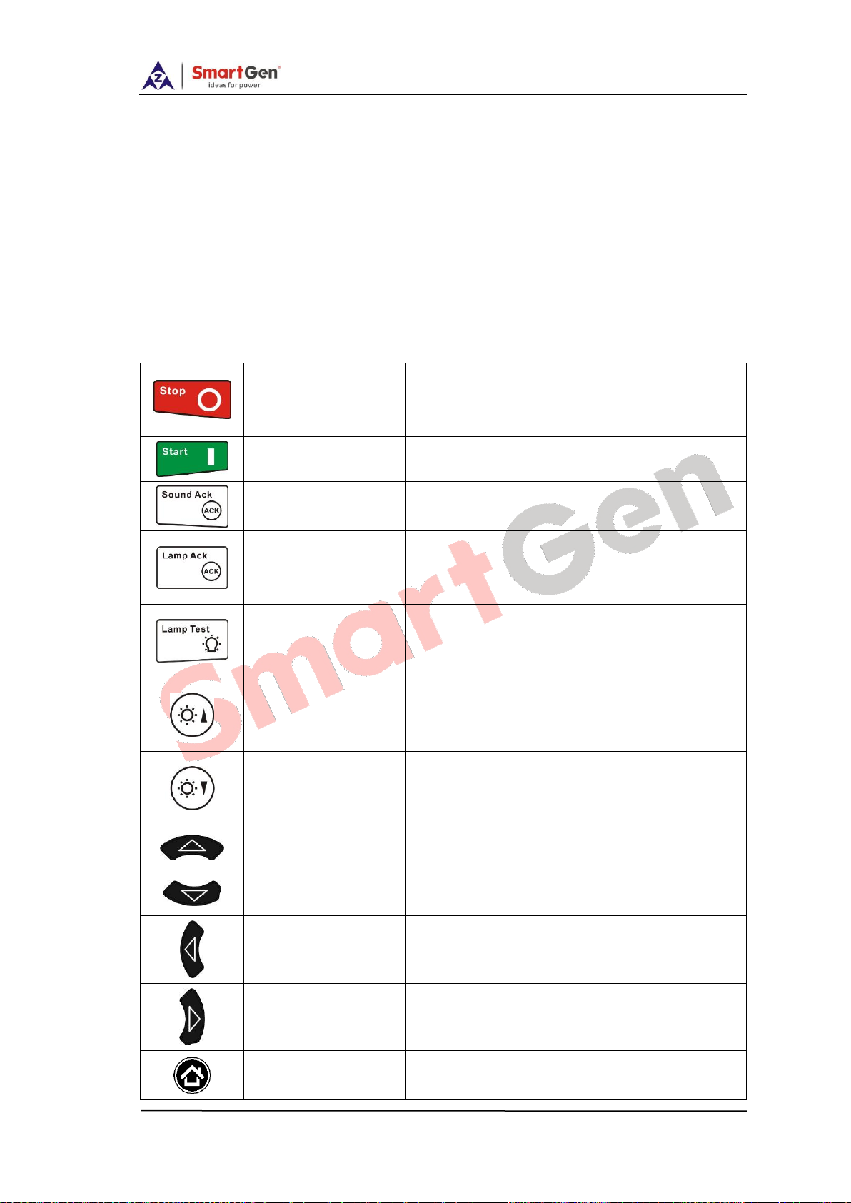
1.Monitor mode, in which and buttons have no effect.
2.Control mode, in which the engine can be stopped and started by press
and pushbuttons; this mode activates only if
HMC9000 is in remote mode.
4.1 REMOTE START/STOP PROCEDURE
Remote mode is selected by pressing the button; a LED besides the
button will illuminate to confirm the operation;
1)Remote start
Press button to start the gen-set, then preheat delay, safety on delay,
start idle delay and warming up delay will be displayed on the screen in turn
(according to the engine settings);
2)Remote stop
Press button, then the screen will display cooling down delay, stop idle
delay, ETS delay and fail to stop delay in turn (according to the engine settings);
Note: If an alarm condition occurs during starting or stopping procedure,
alarm information will be synchronously displayed on HRM3300 LCD.
4.2 ACKNOWLEDGE OPERATION
In case of alarm pressing and buttons will mute the panel

HRM3300 REMOTE CONTROL MODULE USER MANUAL
HRM3300 Remote Control Module 2015-03-25 Version1.1 Page 10 of 9
buzzer and return flash indicator to its illuminating condition. In case of new
alarm situation, sound alarm will be initiated again and the light indicator will
start flashing and the user will have to press the acknowledge buttons again to
clear them.
5. BACK PANEL
HRM3300 controller back panel is shown below:
Terminal connections description:
Terminal
Function
Cable Size
Description
1
B-
1.0mm2
Power supply negative input.
2
B+
1.0mm2
Power supply positive input.
3
NC
Not connected
4
SCR
(REMOTE)
0.5mm2
A CANBUS port which communicate
with main control. Impedance-120Ω
shielded wire with its one end
connected to ground is recommended.
There is 120Ω terminal resistance
inside already; if needed, make
5
CAN(H)
(REMOTE)
6
CAN(L)
(REMOTE)

HRM3300 REMOTE CONTROL MODULE USER MANUAL
HRM3300 Remote Control Module 2015-03-25 Version1.1 Page 11 of 9
Terminal
Function
Cable Size
Description
7
RE (120Ω
resistance)
terminal 6, 7 short circuits.
USB
Factory use
6.APPLICATION DIAGRAM
HRM3300 Application Diagram

HRM3300 REMOTE CONTROL MODULE USER MANUAL
HRM3300 Remote Control Module 2015-03-25 Version1.1 Page 12 of 9
7. INATALLATION
Controller is panel built-in design; it is fixed by clips when installed. The
controller’s overall dimensions and cutout dimensions for panel, please refers to
as following,
Table of contents
Other Smartgen Remote Control manuals
Popular Remote Control manuals by other brands

Sony
Sony PCM-D50 - Portable Linear Pcm Recorder operating instructions

Firstech
Firstech Compustar 2W901R-SS user guide

Panasonic
Panasonic CZ-RWSU2N operating instructions

Modern Forms
Modern Forms F-WC-WT installation instructions

nekos
nekos PIK instruction manual

Mitsubishi Electric
Mitsubishi Electric Lossnay PZ-41SLB-E user manual