Smarti BIO-RID User manual
USER MANUAL
BIO-RID
SMART-I ELECTRONICS SYSTEMS PVT. LTD.(An ISO 9001:2008 certified company)
Corporate Office: Unit No 250,251,252, Second Floor, Building No D-7, Bhumi World, PimplasVillage,
Mumbai- Nashik Highway,BHiwandi, Thane-421302
Tel: + 91-22-6566 6555
Web site: www.smartisystems.com
PRESENCE : MUMBAI - DELHI - BANGALORE – KOLKATA - CHENNAI - AHMEDABAD – PUNE - HYDERABAD
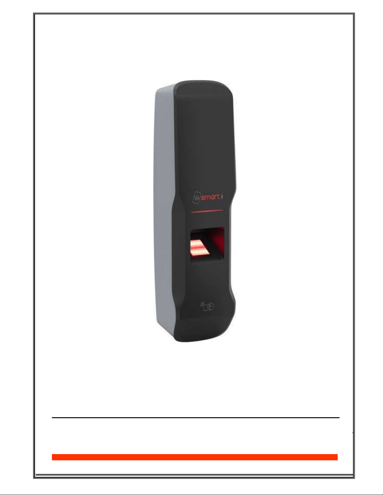
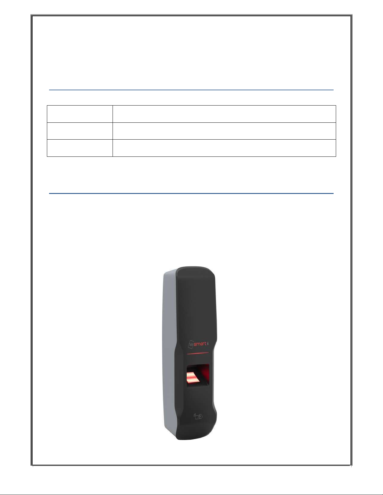
Bio-RID(Reader)

Contents
1. PRODUCT SELECTION ......................................................................................................................... 3
2. INTRODUCTION .................................................................................................................................... 3
3. TECHNICAL SPECIFICATION .............................................................................................................. 4
4. DESCRIPTION OF KEYS & OTHER PARTS......................................................................................... 5
5. OPERATION .......................................................................................................................................... 6
6. CONNECTION DETAILS ......................................................................................................................10
7. DEVICE CONFIGURATION ................................................................................................................. 12
8. RECO ENDED CABLE SPECIFICATION ....................................................................................... 12
9. OUNTING OF UNIT ON THE WALL .............................................................................................. 13
10. CONNECTING TO HOST CO PUTER................................................................................................16
11. ENROLLMENT PROCESS,.....................................................................................................................19
12. TROUBLESHOOTING GUIDE .........................................................................................................................20
1. PRODUCT SELECTION
Particulars Specifications
Model no. SBSK1950
Applications Weigand Reader
2. INTRODUCTION
Smart-i introducing BIO-RID as weigand reader. This is fingerprint device easy to
installation & user friendly operations. Bio-RID the Biometric + Card Reader from smart-i, is very
fast and efficient in all processing and communication functions, faster than any other Biometric +
Card reader in its category, making it an ideal option for any organization with a fairly large or very
large number of employees.

3. TECHNICAL SPECIFICATION
Hardware specification:
Particulars
Description
CPU
32 Bit RISC Arm
Memory
Upto Flash 8 MB
Events/Transactions
1,00,000
No. of templates in sensor 1900/19000
Operation Modes
UID/Card + Finger, UID/Card only ,Card + Finger Card Only
Card & finger
Sensor
High Quality Scratch Resistance Optical Sensor.
Communications Port
TCP/IP, weigand, RS485
Baud Rate
9600bps (Default)
Controller ID
Max 9999
LED
Tricolor LED Bar
Language
English
Power Supply
12 V DC/ 2A (Min)
Enclosure
IP65 ABS Plastic
Color
Silver & Black
Dimension (H X W X D) in mm
(209 x 57 x 47.02)in mm
Mounting
Wall Mounting
Sensor specification:
Particulars
Description
Type
Optical
Image Resolution
500 dpi
Enrollment Time
<
1 sec
Verification Time
<
1sec
Identification Time
1 sec
Template Size
384 bytes
EER/FAR/FRR
<0.1%/0.001%/0.1%
Image Size (Pixels)
272 X 320
Sensing Area (mm)
16 X 19
Special Features:
Particulars
Description
LED indications POWER ON
Valid card/ Finger
ADD card
DEL card
ADMIN Login
Buzzer for different Indication Valid/Invalid →Card/Finger
Finger Addition
Error Indication

4. DESCRIPTION OF KEYS & OTHER PARTS
① ulticolor LED indication
② Card reader
③ Biometric sensor
2
3
1
LED indications with beeps:
Sr. No. Functions LED colors Beeps
1
Finger added Green Two beeps
2
Finger timeout Red Single beep
3
Putting Same finger for enroll Red Single beep
4
Enroll fingers more then 1 Red Two beeps
5
Device Power ON Red Single beep
6
Valid user Green Long beep
7
Invalid user Red Two beeps
8
Invalid finger Red Two beeps
Note:
If the car is not shown within five beep completion then bio-RID will stop to blinking . &
we nee to show car again.
Per user you can a only 2 finger.
If no finger/ card is added in Device , then RED LED will blink continously with a beep .
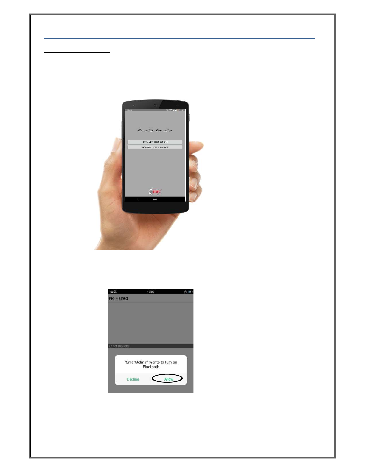
Using obile APK.
1. Open SmartADMIN APK on Android phone
2. Select Bluetooth connection mode from the following options
3. Allow SmartAdmin Apk to turn on the Bluetooth
5. Operation
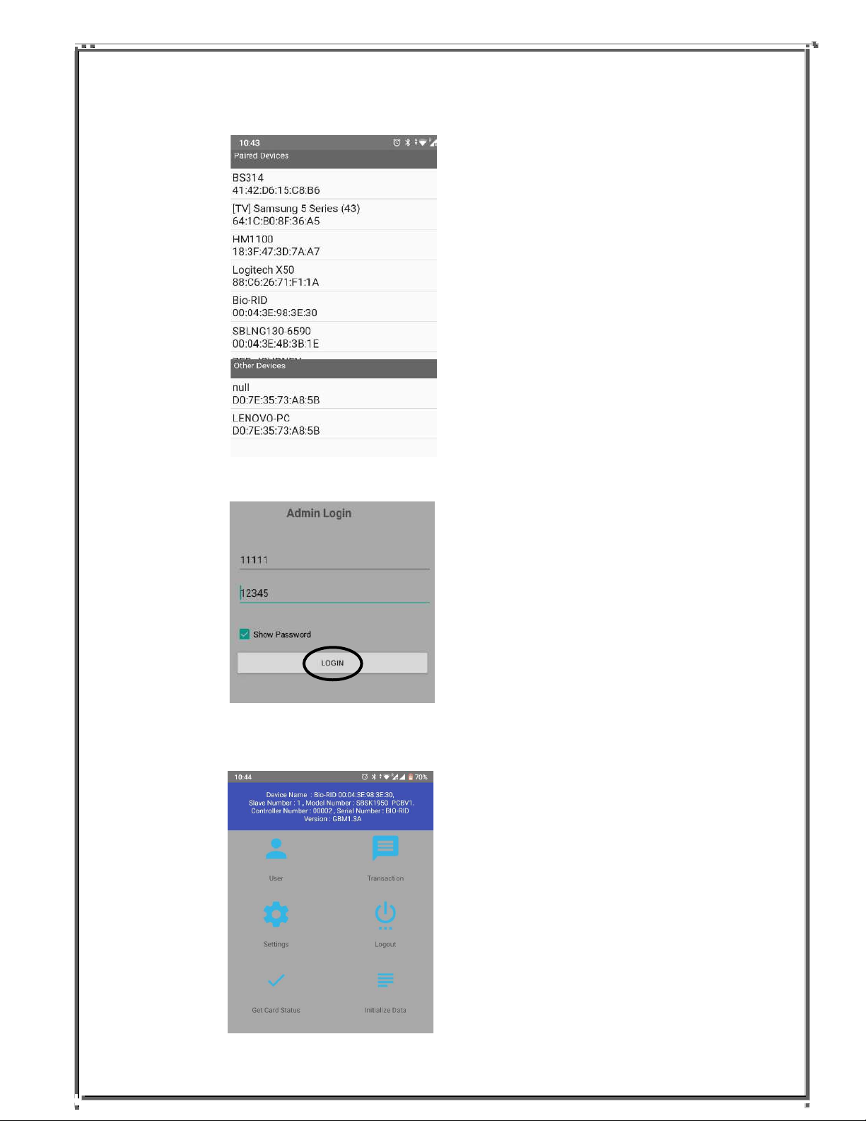
5. Enter USERNAME :11111 andPASSWORD:12345 & Press Login.
4. Scan for the bluetooth Device and select the Device
6. Device display message Bluetooth connected and the window shown below is
opened on apk.
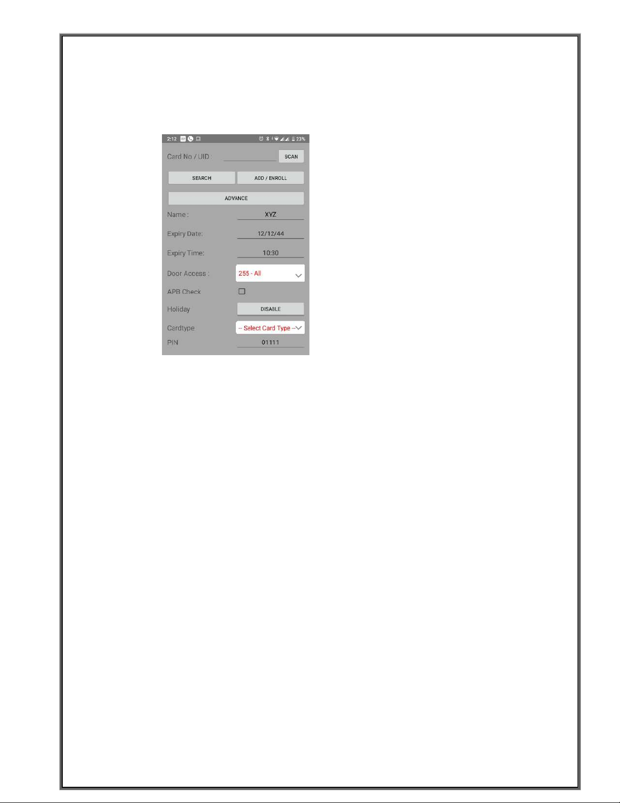
7. To addNew user, click onUser >> Add User .
Now Adduser .: Enter UID/Card number or click on scan option and Show card
across reader.
10. To Delete added User enter the added UID number and click on
Delete.
11. Press : Logout to logout from the device.
8.Click on Advance and Select card type → UID/Card+Finger and Press Enroll.
9. Blue LED will start blinking ,Place Finger on prism of sensor twice , after
finger is enrolled sucussfully message is displayed on apk and LED will turn
Green.
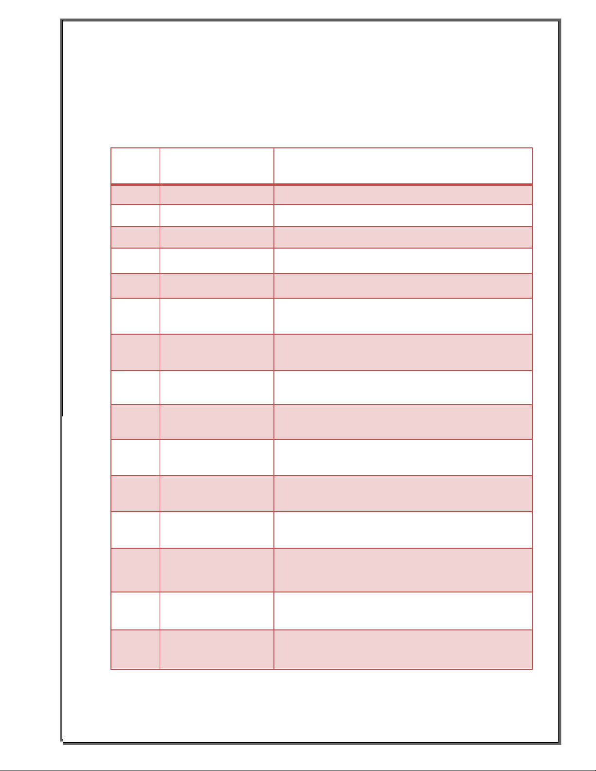
Network setting
Sr. No. Network Setting
Parameters Description
1. IP AddressSet IP address to device for TCP/IP communication
2. Subnet Mask As per your network.
3. Gateway As per your network.
4. Local TCP Port For device indentification and communication
5. Local UDP Port For device indentification and communication.
6. Server IP Set Server IP Address, it is used when MAC security
feature is Enable.
7. PUSH Server1 IP Set Server IP Address where we want to push
transaction data using TCP.
8. PUSH Server1 Port Set Server Port Address where we want to push
transactiondata using TCP.
9. PUSH Server2 IP NA
10. PUSH Server2 Port NA
11. UDP PushServer IP Set Server IP Address where we want to push
transaction data using UDP.
12. UDP PushServer Port Set Server Port Address where we want to push
transactiondata using UDP.
13. HB Server IP Set Server IP Address where we want to push Heart
Beat data. Device sendsall important information to
this server.
14. HB Server Port Set Server Port Address where we want to push
Heart Beat data.
15. HB Time Set Heart Beat Time,this is time delay after which
controller send Device Information to HB Server IP.

BIOMETRIC
READER
TCP/IP
12V DC
Power Supply
CAT5e/ CAT6 FOR
LAN COMMUNICATION
Network Switch
(C)
(A)
TX+
BZ
V+
TAMP
V-
RX-
RX+
LED
TX-
D1
D0
D-
GND
D+
12V
(B)
(D)
GND
12V
ETHERNET RS 485 POWER
READER
WGND OUT
WGND IN
Access Control Device
12V
GND
D0
D1
BZ
LED
TAMP
For Template management
5. OPERATION
6. Connection Details

Bio-RID Connector WIRE details
A
B
C
D
Weigand Reader
Ethernet
RS485
Power
PIN
PIN DESCRIPTION
WIRE
1
POWER + (12Vdc)
RED
2
POWER -
BLACK
PIN
PIN DESCRIPTION
WIRE
1
D+
GREEN
2
D-
WHITE
PIN
PIN DESCRIPTION
WIRE
1
TX+
BLUE
2
TX-
ORANGE
3
RX+
GREY
4
V+
BROWN
5
R-
YELLOW
6
V-
BROWN
PIN
PIN DESCRIPTION
WIRE
1
12V
RED
2
GND
BLACK
3
D0
GREEN
4
D1
WHITE
5
BUZZER
YELLOW
6
LED
BROWN
7
VOILET
. DEVICE CONFIGURATION
Bio-RID as Reader:
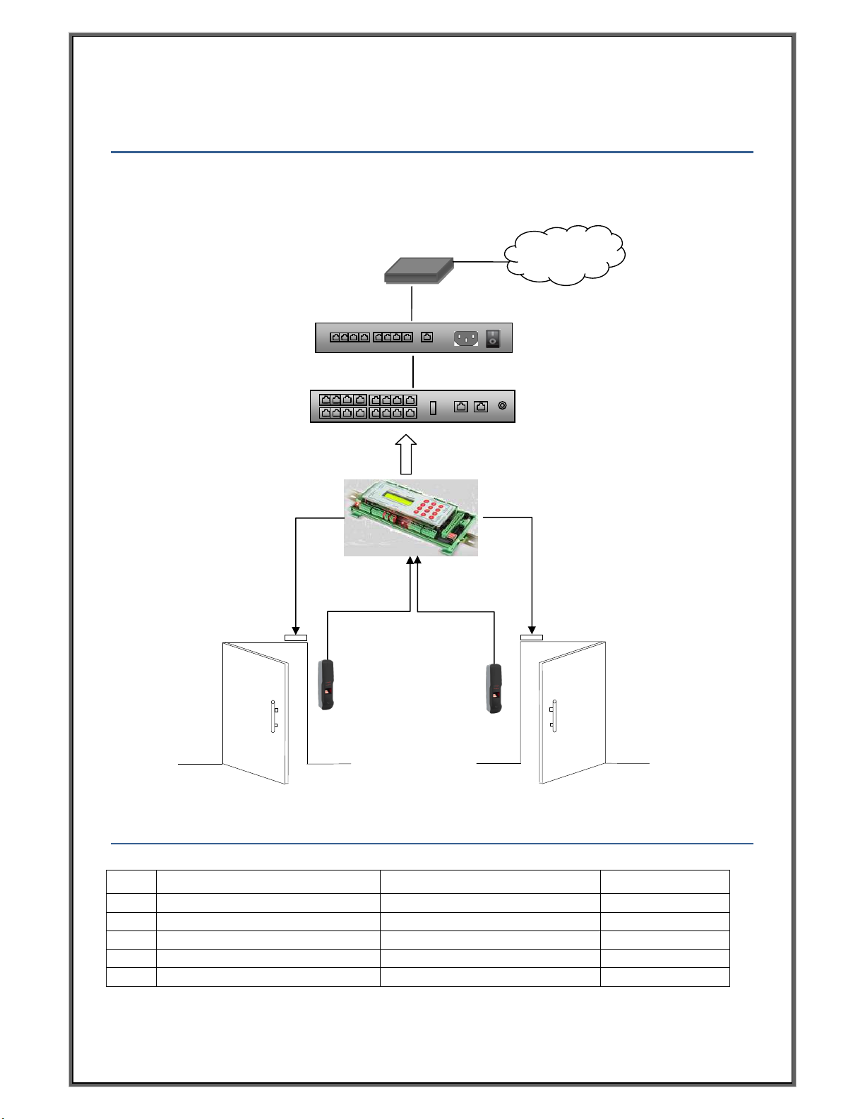
8. RECOMMENDED CABLE SPECIFICATION
Type
Particular
able Spec
Distance
A
Reader (Weigand)
22AWG; 6 core; shielded Cable
Up to 25 meter
B
Egress switch, agnetic contact
22 AWG;2 core; shielded Cable
Up to
10Ft.
Lock
16 AWG; 2 core; shielded Cable
Up to 10 Ft.
D
Unit to Power Supply
22AWG; 2 Core shielded Cable
Up to 10 Ft.
E
LAN Cable
24AWG; CAT5 / CAT6 (4 pair)
Up to 100 meter
Internet
ADSL
Switch
Router
Lock
Lock
To reader section
To reader section
TCP connection
STANDALONE Bio-RID
CONFIGURATION
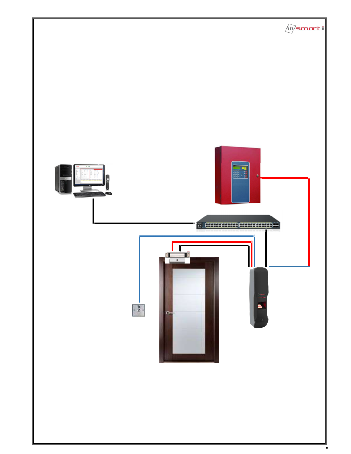
FIRE INTEGRETION PANEL
SMARTi Software
TCP/IP
HUB
EML Lock
TCP/IP
OUT
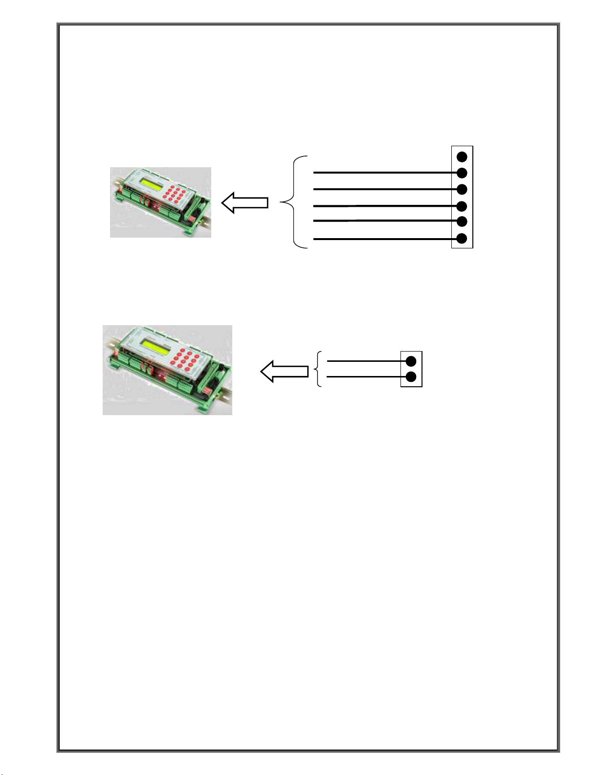
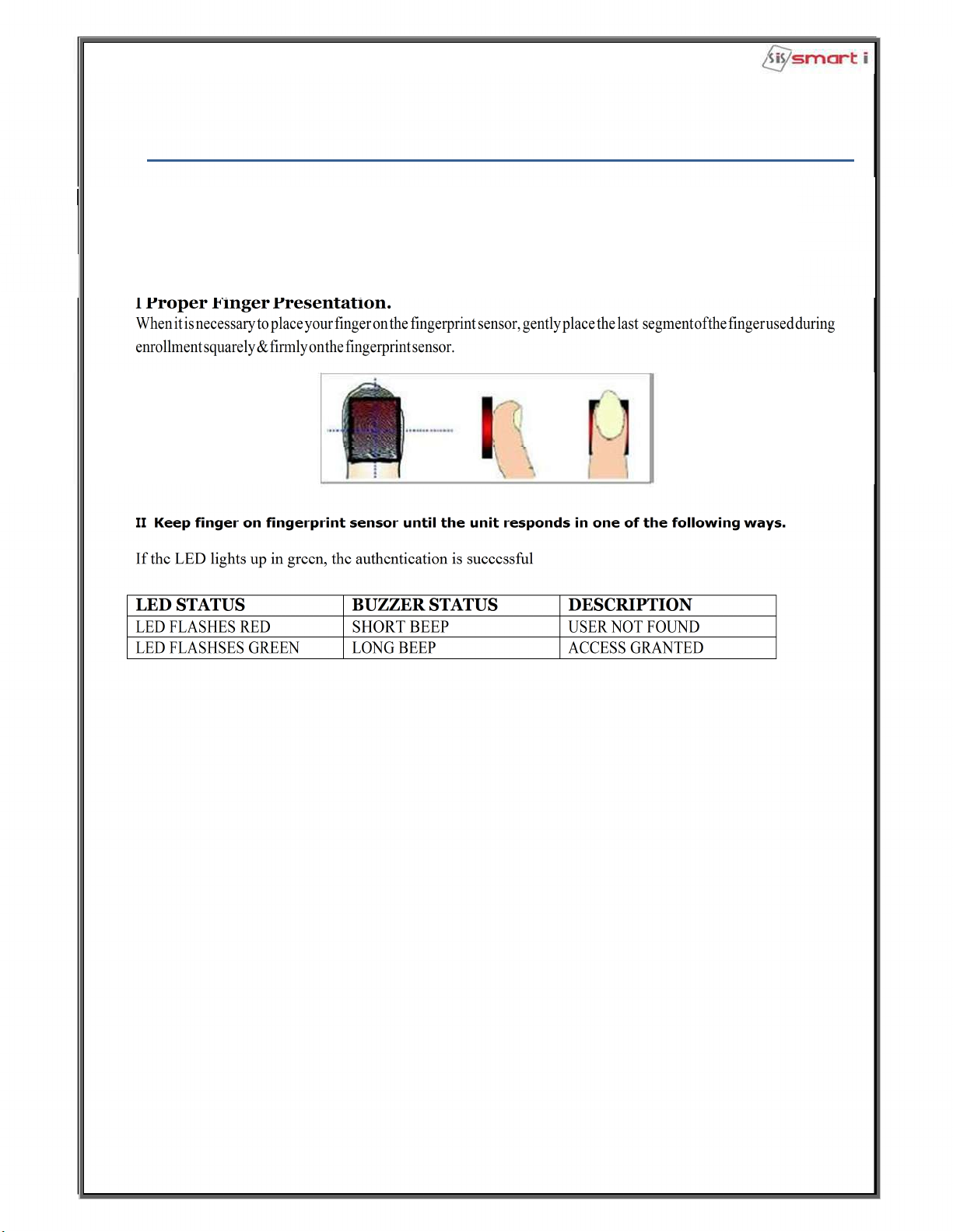
Weigand OUT connection:
RS485 connection:
D+
D-
To controller for template management by TCP/IP comm.
J8
N
LED
D1
D0
GN
12V
Brown
White
Green
Black
Red
J12
In weigand out mode need to use this connection to connect with controller at
it’s reader section.
LED
D1
D0
GN
12V
To reader section

30.0 mm
30.0 mm
80.0 mm
81.0 mm
30.0 mm
18.0 mm
28.5 mm
11.0 mm 11.0 mm
40.0 mm
186.79 mm
4.00 mm
Pan head self
threaded star
(M3*10) screw
in wall
Pan head self
threaded star
(M3*10) screw
in wall
Pan head
self
threaded
star (M3*10)
screw in wall
9. Mounting on Unit on Wall

Notch to Fit the
Device
Notch to Fit the
Device
Note. Place the Plate on Wall and Fit the Device with a Screw.

10. Connecting to host Computer


Testing the Connection To test the connection following is the under mentioned steps
Step 1
At the PC, Click Start -> Run -> Type “command” and press ‘OK’.
Step 2
Type “telnet ipaddress port"
(The IP Address should reflect that of your Bio-RID unit)
Note: -
If unsuccessful, either “Connect failed will be displayed, please follow
the above steps
carefully and test the connection.
Successful Connectivity
Unsuccessful connectivity
11. Enrollment Process
Table of contents
Popular Card Reader manuals by other brands


Memorex
Memorex USB SD/MMC CARD READER user guide

UTC Fire and Security
UTC Fire and Security Interlogix ACL800DIN-RDRMF Installation sheet

Transcend
Transcend Compact Card Reader S1 Specification sheet

C Prox Ltd
C Prox Ltd MINI-PROX user manual

24PetWatch
24PetWatch Microchip Reader user manual

Delkin Devices
Delkin Devices eFilm Pocket Reader-MS user manual