Smartlink LUX-TWR Assembly instructions

SMARTLINK LUX–TWR RADIO PIR MANUAL
PAGE 1
LUX–TWR
Two Way Wireless PIR Motion Sensor Installation and Setup Guide
APPLICATION & OVERVIEW
The Smartlink LUX–TWR Wireless PIR Motion Sensor is designed
for use with control/transceivers that accept Smartlink two-way tech-
nology. Lux is intended for use in residential and light commercial
installations and incorporates many advanced features designed to
ensure its reliable performance.
The dual element pyro-electric sensor detects movement within a
specic coverage area by sensing the infrared energy that is emitted
from an intruder moving across the sensor's eld of view. A change in
the infrared energy across multiple detection zones is then processed
to determine if the occurrence qualies as a legitimate motion detection
event. If it does then an alarm signal is transmitted to the controller.
The two-way radio (RF) in the LUX–TWR transmits alarm, tamper,
supervisory, and low battery messages to the control/receiver. Each
sensor has a unique TXID number which is enrolled into the control
during installation. With its two-way capability, the LUX–TWR radio
listens after every transmission for a positive acknowledgment from
the control. This makes the sensor very energy efcient since it
doesn't waste battery power repeating transmissions unless they
are not acknowledged.
Like all battery powered motion detectors, the LUX–TWR has a
mandatory sleep cycle function to help extend the battery life. After
detecting motion, the sensor's radio will transmit the event to the control
and wait for acknowledgment. Upon acknowledgment the sensor will
enter the mandatory sleep cycle. During the sleep cycle time it cannot
transmit additional events. There are two (2) time choices for the
sleep cycle selected via DIP Switch #4. After the sleep cycle expires
the sensor will once again be capable of transmitting a new event.
The LUX–TWR includes the unique Smartlink LUX Security/Conve-
nience LightTM with a bright white LED providing lighting for safety
and convenience.
FEATURES
• Wireless two-way communication
• Dual element pyroelectric sensor
• Selectable pulse count
• Selectable Hi/Lo range
• Excellent immunity from white light, RF, and ESD interference
• Bi-Colour RF Acknowledge LED (Green + Org/Red)
• Security/Convenience TM LED (White)
• Long life Lithium batteries supplied
• Low battery trouble signal
• Sleep Cycle "Battery Saver" (2 time settings)
• Periodic (64 min.) Supervisory check-in
• Cover tamper protection
• Swivel mounting bracket included
• Optional deluxe 90° swivel bracket for ceilings sold separately
SPECIFICATIONS
• Dimensions: 112(h) x 72(w) x 48(d) mm
• Mounting Height: 2.1m – 2.4m
• Sensor: Dual element pyroelectric
• Coverage: Hi Range = 15m x 15m @ 88.2°
Lo Range = 12m x 12m @ 88.2°
20 dual element zones (2 Long, 10 intermediate, 4 mid, 4 short)
plus look down (creep zone)
• Pulse Count: 1-2 or 3-4, selectable
• Sleep Time: Selectable 30 sec. or 120 sec.
• RF Signal Acknowledge Indication: Bi-Colour LED
• Security/Convenience Light: White LED
• Warm Up Period: 10 seconds
• Operating Voltage: 3.0 Volts DC
• Battery Type & Size: 2 x Lithium CR123A
• Quiescent Current: < 10 µA
• Operating Temp: 0° to +50° C
• Humidity: 95% RH (max.), non-condensing
• Frequency: 902 - 928 Mhz channel hopping
PACKAGE CONTENTS
1 - LUX–TWR PIR electronics assembly & back housing
1 - Standard swivel bracket, locking disc, screws & anchors
1 - Blanking plug
2 - CR123A Lithium Batteries
1 - Cover locking screw
1 - Bracket locking screw
With unique security/night light!

SMARTLINK LUX–TWR RADIO PIR MANUAL
PAGE 2
INSTALLATION
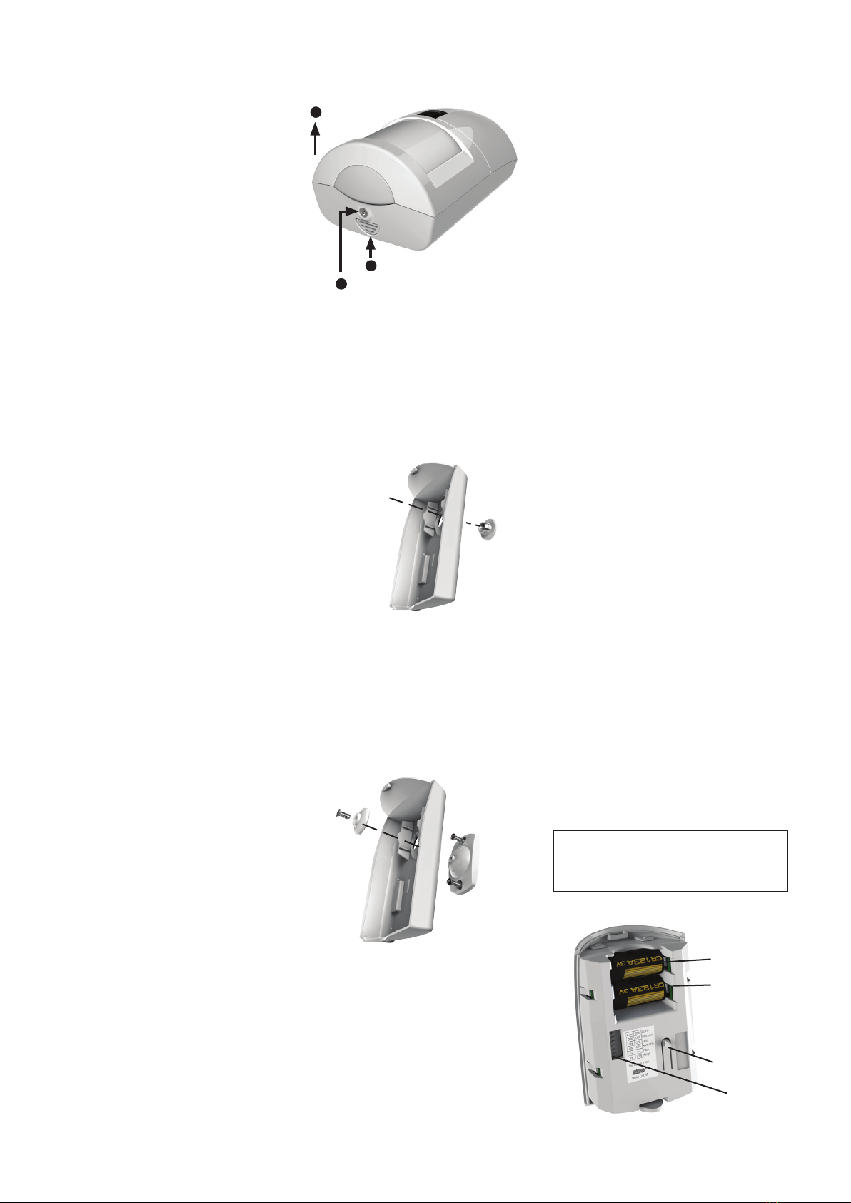
1. OPENING THE HOUSING - Remove the locking
screw along the bottom (if installed). Push in the
retainer tab and lift the front away from the backplate.
2. MOUNTING - To mount directly onto a wall WITHOUT
the swivel bracket, start by inserting the supplied
blanking plug into bracket mounting hole. This is
very important! See Figure 3. Next, locate the 9
dimple marks on the inside of the backplate. Choose
2 (or more) of these for use as the screw mounting
holes. Drill out the necessary holes using 1/8" bit.
To prevent air or contaminants from getting into the
sensor, DO NOT leave any exposed or unused holes!
To mount with the standard Swivel Bracket, start
by attaching the bracket's base to the wall in the
chosen location. Next, t the backplate over the
bracket and install the locking disc with bracket
screw provided. Do not tighten this screw until the
angle and direction have been adjusted as required.
GUIDELINES FOR USE
The LUX–TWR Sensor is for indoor use only. It may
be mounted directly on a wall or in a corner, with or
without the supplied swivel bracket.
It is recommended that the LUX–TWR be located
within 30m of the control/transceiver. While an open-
air range of 100m or more is possible, adverse indoor
and environmental conditions can signicantly reduce
the actual transmission range. Small changes to the
sensor's mounting can often make a big difference in
transmission range.
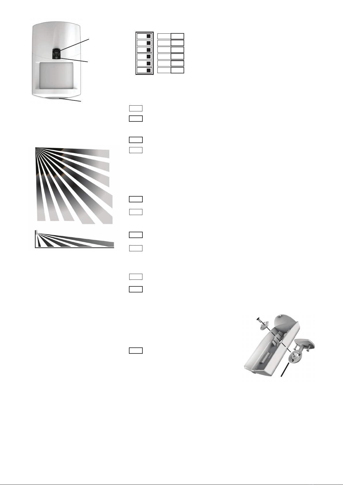
Always locate the sensor where a person is most likely
to walk across the coverage pattern. Aim the sensor
so that it faces inward toward a solid reference point
such as a wall. Corner mounting often provides the
best detection coverage. See Figure 1.
Choose the location and mounting height carefully.
For optimum performance the recommended mounting
height should be 2.1m ~ 2.4m. The surface must be
solid and free of any noticeable vibrations. As with all
PIR sensors, select a location that avoids direct sunlight,
glass windows, replaces, heating or cooling sources,
and areas of high humidity. Always ensure the sensor
has a clear line of sight of the area to be protected.
Note that infrared energy does not pass through solid
objects, including glass.
DO NOT mount a wireless sensor near metal duct
work or other large metallic surfaces that might shield
or adversely affect the RF signals. Prior to permanent
mounting, we recommended a walk test be performed
with the control/transceiver to verify acceptable opera-
tion of the wireless sensor at its intended location.
Installation in areas where animals can roam is not
recommended unless the sensor is a Smartlink Pet
Aware model.
Windows should be kept closed in any area which has
an armed motion sensor.
PROGRAMMING TO A CONTROLLER
For Two Way Radio programming to your controller
refer to the controller/control panel's manual.
NOTE: The optional Deluxe Swivel Bracket (106-
169) may be purchased separately. The deluxe
bracket provides wall or ceiling mounting with a
wider range of vertical and horizontal adjustment.
Refer to page 4.
Figure 2. Opening the Housing
Figure 3. Prep for Wall Mounting (No Bracket)
Blanking Plug
Bracket mounting hole
Backplate
Figure 4. Standard Swivel Mounting
Swivel Bracket
Locking
Disc
Backplate
Tamper Switch
2 x CR123A Lithium
Batteries
Option Switches
Figure 5. Back View of Sensor
Battery #2
Battery #1
1Remove lock screw if fitted
2Push locking tab
3Pull to separate
BATTERIES
The LUX–TWR holds 2 x CR123A Lithium batteries.
The estimated service life is 5 to 7 years in a typical
residential installation with the Sleep Cycle set to LG
(Long),
Battery #1 (lower) is supervised for low voltage. When
the sensor detects the voltage has reached 2.6 VDC or
less (under load), a Sensor Low Battery trouble will be
transmitted to the control/transceiver. This trouble will
be attached to all future transmissions until fresh new
batteries are installed. Battery #1 is the primary power
source for all critical functions (motion detect and radio
transmission) of the LUX–TWR sensor.
Battery #2 (upper) is not-supervised for low voltage. This
battery is a secondary (reserve) power source for the
LUX–TWR critical functions, but it is the primary (sole)
power source for the White Security/Convenience LED.
The White Security/Convenience LED will not operate
without a good battery installed in Battery #2 location.
We strongly recommend installing a battery in both
locations. These 2 batteries are electrically isolated
in such a way that critical functions of the LUX–TWR
can draw power from either battery, but the White
Convenience LED can only draw power from Battery #2.
To clear a sensor low battery trouble condition, remove
old batteries and WAIT AT LEAST 20 seconds before
installing new batteries. Once the new batteries are
installed, trip the sensor a couple of times. This should
send an "all good" and clear the low battery trouble.
Caution: Excessive use of the White Security/
Convenience LED will reduce the life of Battery #2.
More importantly, because the LUX–TWR sensor is
able to tap into Battery #2 for secondary power, any
reduction of its life naturally reduces the overall
operational life of the sensor. If maximum sensor
operational life is the top priority, the Security/
Convenience LED may be disabled by turning DIP
Switch #3 OFF.
BATTERY REPLACEMENT
Use only approved 3V Lithium batteries. Replace both
batteries at the same time and with same date code if
possible. Replacements can be obtained from Smartlink
Corporation or distributors.
1. Remove sensor from back housing.
2. Remove both old batteries from sensor.
3. WAIT AT LEAST 20 SECONDS before installing
new batteries.
Note that LUX is supplied with both batteries tted
in reverse for safe transportation.
Note the correct polarity when inserting the batteries.
Installing the batteries in reverse will not harm the
unit but it will not operate correctly
Do not bend or damage the metal battery holder
contacts. Approved 3.0 Lithium Batteries are Ultralife
C&17335, Panasonic CR123A, Duracell DL123A,
Sanyo CR123A,
4. Re-test sensor operation with the control.
BATTERY WARNING: Risk of re, explosion and
burns. Do not attempt to recharge or disassemble.
Do not incinerate or expose to heat above 100°C.
Dispose of used batteries properly. Keep away
from children.

SMARTLINK LUX–TWR RADIO PIR MANUAL
PAGE 3
FUNCTIONAL 'SYSTEM' TESTING
A system test should be done by physically walking
across the LUX–TWR coverage pattern while the system
is fully armed. NOTE: Allow time for the Sleep Cycle
Timer to expire before testing. Always notify the Cen-
tral Monitoring Station prior to performing any testing.
WALK TEST
Walk test is a way to verify that the sensor is operating
as desired and in the optimum location. Slow and short
steps should be taken across the coverage zones in
both directions. When motion is detected, the White
LED should blink once followed by a quick blink of the
Green RF ACK LED. The Green LED indicate that the
sensor transmitted an alarm signal an that the control/
transceiver acknowledged that transmission. See
paragraph titled: RF ACKnowledge LED
NOTE: Walk Test mode bypasses the Sleep Cycle timer
allowing the Sec./Convenience LED and the RF ACK
LED to operate regardless of DIP switches 2, 3, and 4.
SENSOR WALK TEST
This is started by opening and closing the sensor
housing to violate the tamper switch. Sensor Walk
Test will end after 10 minutes.
RF ACKnowledge (Green) LED
This LED is located in the clear lens on the sensor front.
It's a bi-Colour LED providing visual status of the two-way
acknowledge (response) from the control/transceiver.
In bright lighting conditions this LED may be difcult
to see. DIP Switch #2 allows the Green LED to be
disabled for all operations except the Walk Test Mode.
GREEN blink = Sensor has successfully transmitted a
violation (alarm) transmission to the transceiver and
that signal has been received and acknowledged by
the transceiver. The green blink is not provided for
a sensor restore transmission..
ORG/RED blink = Sensor was not successful in trans-
mitting after multiple attempts.
DISABLING RF ACKnowledge (Green) LED
DIP Switch #2 allows the RF ACKnowledge (Green)
LED to be disabled for regular operation, helping pre-
vent unauthorized persons from learning the coverage
patterns. It also helps extend battery life. Place DIP
Switch #2 in the "NO" position to disable the RF ACK
LED, or in the "YES" position to enable the RF ACK LED.
NOTES: DIP Switch #2 does not disable this LED from
working in the Walk Test Mode.
Creep Zone
"Lookdown"
Security/
Convenience
LED (White)
RF ACK
Bi-Colour LED
(Green + Org/Red)
Figure 6. Front View of Sensor
COVERAGE PATTERNS
Figure 1. Top and Side Views
(assumes range is set to "HI")
2.1m
0.3m 1m 3m 6m 15m
6. After enrolling the sensor into the control and setting
the Option Switches, reposition sensor over the
back housing and snap it into place. This action
will activate the Walk Test mode for the next 10
minutes. Perform an immediate Walk Test accord-
ing to the procedure that follows.
7. If the swivel mount bracket was used then it will be
possible to adjust (ne tune) the Sensor coverage.
If the swivel bracket was not used, and the sensor
was xed mounted to the wall, the coverage pattern
is based on the mounting height and position.
8. After Walk Testing has been completed, secure
the sensor to the back housing using the locking
screw provided (small countersunk screw).
PULSE COUNT (Switch 6)
Sensor must detect 1 or 2 events in the
coverage area before an alarm is created.
FUTURE (Switch 1)
Sensor must detect 3 or 4 events in the
coverage area before an alarm is created.
RANGE (Switch 5)
Sensor is set for the shorter detection range
(approximately 12m.)
Sensor is set for the longest detection range
(approximately 15m.)
To extend battery life, a mandatory sleep cycle (2 time
settings) begins after each alarm transmission. After
the Sleep Cycle expires, there must be ~8 seconds of
quiet (no movement) before the sensor will be allowed
to detect and send another radio transmission.
Long (120 secs.) Until this timer expires
the sensor cannot transmit another event.
SECURITY/CONVENIENCE LED (Switch 3)
This switch is not currently used.
Short (30 secs.) Until this timer expires
the sensor cannot transmit another event.
Sec/Convenience LED is NOT ENABLED
except for the Walk Test.
Sec/Convenience LED is ENABLED for
other functions other than Walk Test and
audible alarms. See back page for details.
RF ACK LED (Switch 2)
RF ACK (Green) LED is NOT ENABLED
except during the Walk Test Mode.
RF ACK (Green) LED is ENABLED, and
should blink Green upon a detect and
positive acknowledgment from the control.
SLEEP CYCLE (Switch 4)
5. DIP SWITCH OPTION SETTINGS
Green = Sensor transmitted and received a positive
ACK (acknowledgment) from the Control/
Transceiver.
Org/Red = Sensor attempted to transmit but did not
receive an ACK (acknowledgment) from the
Control/Transceiver.
Figure 7. DIP Switches
1 - 2
HI
SH
YES
NO
N/A
3 - 4
LO
LG
NO
YES
N/A
PULSE COUNT
RANGE
SLEEP CYCLE
SEC/CONV. LED
RF ACK. LED
FUTURE USE
*Factory default, all off
ON OFF*
1 - 2
HI
SH
YES
NO
3 - 4
LO
LG
NO
YES
N/A
ANTI-TAMPER SWITCH
This switch detects the separation of the front housing
from the backplate, resulting in a signal being transmitted
to the control/transceiver that will cause the associated
zone to become violated. Snapping the front housing
back onto the backplate will transmit a restoral.
A deluxe 90° swivel bracket may be purchased and
used in lieu of the standard swivel bracket. This bracket
has a short extended arm and allows the sensor to be
aimed at up to a 90° offset from the wall or base. This
bracket also allows the sensor to be drop mounted
from a ceiling.
OPTIONAL DELUXE 90° SWIVEL MOUNT
Backplate
Deluxe
90° Swivel
Bracket
Locking
Disc
Figure 8. Optional 106-169 Deluxe 90°
Swivel Bracket

SMARTLINK LUX–TWR RADIO PIR MANUAL
PAGE 4
LIMITATIONS
While the LUX–TWR Passive Infrared (PIR) Motion Detector is a highly reliable motion detection device, it does not offer guaranteed protection against
burglary. Any intrusion detection device is subject to compromise or failure to warn for a variety of reasons:
PIR Detectors can only detect movement within a specic coverage area as diagrammed in this manual. To detect movement, the PIR Detector senses the
infrared energy that is emitted from an intruder moving across the sensor's eld of view.
PIR Detectors do not provide volumetric area protection. They create multiple beams of protection. Intrusion can only be detected in unobstructed areas
covered by those beams.
PIR Detectors cannot detect motion or intrusion that takes place behind walls, ceilings, oors, closed doors, glass partitions, glass doors, or windows.
The radio transceiver only provides communications. It does not have anything to do with detecting motion.
The LUX–TWR PIR is not a Life Safety device. The Security/Convenience Light feature is not a substitute for, nor should it ever be utilized as a substitute
for a visual notication appliance.
DOCUMENT PART NUMBER 890-046
Rev1 June 2017
For products:
100-835 Smartlink LUX–TWR Two Way Radio PIR
© 2017 Ness Corporation Pty Ltd ABN 28 069 984 372
Specifications may change without notice.
A division of Ness Corporation Pty Ltd
Unit 4/56 Norcal Rd,
Nunawading VIC 3131 Australia
Tel: +61 3 9875 6400 Fax: +61 3 9875 6422
Email: [email protected]
Web: www.smartlink.com.au
Popular Accessories manuals by other brands

Phonocar
Phonocar 5/872 Manual instructions

Olimpia splendid
Olimpia splendid PELER 1 Instructions for use and maintenance

PNI
PNI SmartHome WP800 user manual

Schwaiger
Schwaiger SDLR42USB user guide

PCB Piezotronics
PCB Piezotronics 356A61/NC Installation and operating manual

Klarstein
Klarstein 10032797 manual