SmartRoom WL-SR-SF-01 User manual

SmartRoom
Wireless Wall Switch Series
Quick Guide
Please refer to the software instruction manual
or download the Software Download Guidance
for more information if it is necessary.


© Nanjing IOT Sensor Technology Co.,Ltd. 2013
Publication Number:2013-0627.1
The manual is issued by Nanjing IOT Sensor Technology Co., Ltd. It is without warranty.
We reserve the right to change and modify misprinted and incorrect information and improve
programs or devices at any time without notice. Such modifications will be written in the
new- edition of the manual.
The reproductions of the content of the manual, in whole or in part, are strictly prohibited
without the written consent from Nanjing IOT Sensor Technology Co., Ltd. The using of the
content in other computers capable of reproducing and retrieving and reverse engineering
are also forbidden.
Copyright

SmartRoom, IOT Sensor, Wulian are all the registered trademarks of Nanjing IOT Sensor
Technology Co., Ltd.
Usage of these trademarks is strictly prohibited without the written authorization and
permission from Nanjing IOT Sensor Technology Co., Ltd. Legal action will be taken against
unauthorized use of these trademarks.
All other products mentioned in the manual or service name is the trademark or registered
trademark of the respective companies.
Trademark

● Directly control the specific device through the key of the switch.
● Wirelessly control the corresponding devices through various mobile smart terminals
● Through ZigBee mesh linkage, the switch can control a single source or multiple sources at
the same time
● Multiple Decorative Covers are offered. Users are able to choose their own style.
Attention: to achieve linkage function, other Wulian brand ZigBee products are required.
Basic Function
1
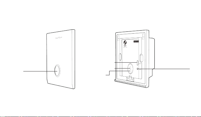
Function Illustration
Push Button
Push Button
Decorative Cover Main Body
Multi-Functional Key
Status Indicator Light System Indicator Light
2
Single Button Switch
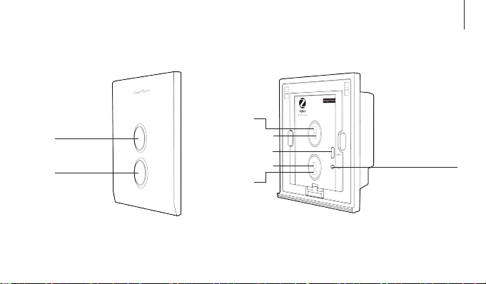
Push Button
Push Button
Status Indicator Light
Status Indicator Light
Push Button
Multi-Functional Key
Push Button
System Indicator Light
3
Two Buttons Switch
Function Illustration
Decorative Cover Main Body
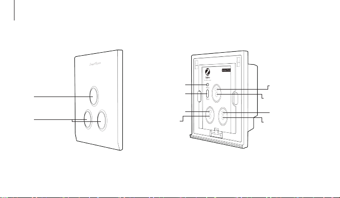
Push Button
Push Button
Status Indicator Light
Status Indicator Light
Push Button
Multi-Functional Key
Push Button
4
System Indicator Light
Status Indicator Light
Push Button
Three Buttons Switch
Function Illustration
Decorative Cover Main Body
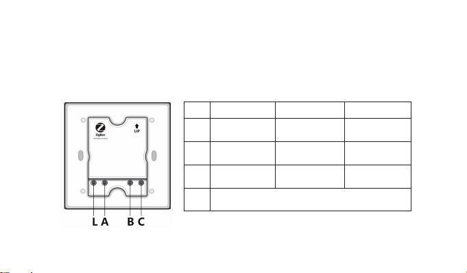
1. Connecting wire as the following picture:
Installation Steps
5
Port Single Button Two Buttons Three Buttons
A
B
C
L
One-way Load
Live Line Output
Two-way Load
Live Line Output
∕
∕ ∕
Live Line Input
Single Live Line Switch
One-way Load
Live Line Output
One-way Load
Live Line Output
Two-way Load
Live Line Output
Three-way Load
Live Line Output

Warning: Please confirm the electrical power source is off before installation. Electricity
manipulation is dangerous. Only professionals are allowed to perform installation.
6
Port Single Button Two Buttons
A
B
L
One-way Load
Output
∕
Live Line Input
Null Line Input
Installation Steps
N
Null and Live Line Switch
One-way Load
Output
Two-way Load
Output
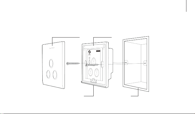
2. Press the Buckle Button and remove the Decorative Covers. Fix the product in the Wall
Mount Base with two screws. Installation method is same to the standard wall switch.
Decorative Cover Main Body
Wall Mount BaseBuckle Button
7
Installation Steps
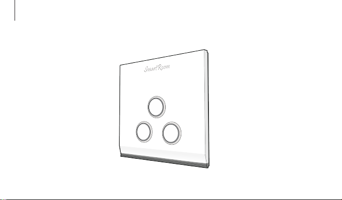
3. Attach the Decorative Cover. Installation is complete. (Please finish setting up the
network before installation.)
8
Installation Steps

1. Please make sure the gateway(additional purchase) ZigBee network is working and this
product has power within effective communication distance of gateway before setting.
Attention: for more details please refer to wireless gateway instruction.
Networking Setting
9
Note: The guide is taking the three buttons switch as an example.
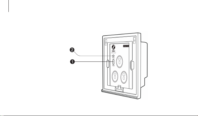
2. Press Multi-Functional Key 4 times to join ZigBee network. System Indicator Light stays
flickering when searching network. Upon successful connection, System Indicator Light will
stay lit in 2 seconds and then goes off.
Press Multi-Functional Key 4
times quickly. Each press must
be done within 1 second
1
System Indicator Light goes off
after staying lit in 2 seconds 2
10
Networking Setting
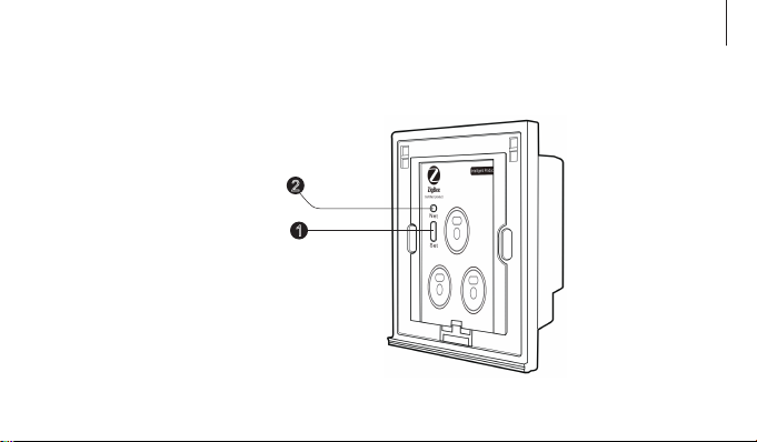
3. Press Multi-Functional Key 10 seconds to restore to factory setting and exit ZigBee
network.
11
System Indicator Light
goes off after flickering
4 times
1
Press Multi-Functional
Key 10 seconds
2
Networking Setting

Status Indicator Light
Status Indicator Light
Push Button
Multi-Functional Key
Push Button
4. Press and hold the Multi-Functional Key, then quick click the Push Button which wanted
to binding 3 times, sending the binding request. The Application Indicator Light will flashes 3
times if successful, flashes 6 times in 20 seconds if failed.
12
Networking Setting

1. Each Push Button in the panel is linked with one corresponding switch. Pushing the button
repeatedly allows changing the loaded condition. When the load condition is off, Status
Indicator Light stays lit. Otherwise, Status Indicator Light goes off.
Usage
2. Users can operate the switch through mobile smart terminal. Please refer to Software
Download Guide.
13

Product Standard
IEEE802.15.4(ZigBee)
100m( visible)
14
Each resistive load 300W (filament lamp, spotlight)
Load Type
Each inductive and capacitive load,150W(energy
saving lamp, fluorescent lamp, LED)
Each resistive load 1500W(filament lamp.spotlight),
2000W in total
Each resistive load 1200W, each inductive and
capacitive load 800W, total load≤1600W
Each inductive and capacitive load1000W(energy
saving lamp, fluorescent lamp, LED), 1500W in total
Communication Way
Communication Distance
Single Live Line
Null and Live Line
Single Live Line
High-Power

Product Standard
15
Power Supply
Working Temperature
Weight
Net Weight
Color
110~240V
-10℃~+45℃
250g
200g
Various materials and colors are offered

Ordering Information
16
Wireless One Button Single Live Line Switch
Wireless One Button Single Live Line High-Power Switch
Wireless One Button Single Live Line Switch (Tempering Glass)
Wireless Two Button Single Live Line Switch
Wireless Two Button Single Live Line High-Power Switch
Wireless Two Button Single Live Line Switch (Tempering Glass)
Wireless Three Button Single Live Line Switch
Wireless Three Button Single Live Line Switch (Tempering Glass)
WL-SR-SF-01
WL-SR-SFD-01
WL-SR-SFG-01
WL-SR-DF-01
WL-SR-DFD-01
WL-SR-DFG-01
WL-SR-TF-01
WL-SR-TFG-01
SRPN1303101
SRPN1307101
SRPN1303111
SRPN1303102
SRPN1307102
SRPN1303112
SRPN1303103
SRPN1303113
Product Model Art.No.
This manual suits for next models
19
Table of contents
Other SmartRoom Switch manuals


Popular Switch manuals by other brands

NETGEAR
NETGEAR S350 Series Hardware installation guide

Smartwares
Smartwares SHS-51001-EU installation instructions

Cisco
Cisco Catalyst 3560-C Getting started guide

TRENDnet
TRENDnet TEG-S081FMi user guide

Mellanox Technologies
Mellanox Technologies SwitchX-2 MSX6018F-1SFS Hardware user manual

schmersal
schmersal BN 85 operating instructions

SimworX
SimworX Pro Series ARB Lever and Brake Bias Set Setup manual

Exsys
Exsys EX-1189HMVS-2 manual

Blade Network Technologies
Blade Network Technologies RackSwitch G8000 Application guide

ADDER
ADDER CATx user guide

Avaya
Avaya 8600 Technical configuration guide

Tripp Lite
Tripp Lite NetDirector B024-HU08 owner's manual


