SMC Corporation EX250-SDN1-X102 User manual
No.EX※※-OME0003-F
PRODUCT NAME
SI unit for DeviceNetTM
MODEL / Series / Product Number
EX250-SDN1
EX250-SDN1-X102

-1-
No.EX※※-OME0003-F
Table of Contents
Safety Instructions 2
Product Summary 8
Model indication and How to Order 9
Summary of Product parts 9
Mounting and Installation 10
Installation 10
Wiring 11
Indication and Settings 17
DeviceNetTM objects 23
Maintenance 33
Troubleshooting 34
Specifications 42
Specifications 42
Dimensions 43
Option 44
-2-
No.EX※※-OME0003-F
Safety Instructions
These safety instructions are intended to prevent hazardous situations and/or equipment damage.
These instructions indicate the level of potential hazard with the labels of "Caution", "Warning" or "Danger".
They are all important notes for safety and must be followed in addition to International Standards
(ISO/IEC)*1), and other safety regulations.
*1) ISO 4414: Pneumatic fluid power -- General rules relating to systems.
ISO 4413: Hydraulic fluid power -- General rules relating to systems.
IEC 60204-1: Safety of machinery -- Electrical equipment of machines .(Part 1: General requirements)
ISO 10218: Manipulating industrial robots -Safety.
etc.
Caution
Caution indicates a hazard with a low level of risk which, if not avoided, could
result in minor or moderate injury.
Warning
Warning indicates a hazard with a medium level of risk which, if not avoided,
could result in death or serious injury.
Danger
Danger indicates a hazard with a high level of risk which, if not avoided, will
result in death or serious injury.
Warning
1. The compatibility of the product is the responsibility of the person who designs the
equipment or decides its specifications.
Since the product specified here is used under various operating conditions, its compatibility with specific
equipment must be decided by the person who designs the equipment or decides its specifications
based on necessary analysis and test results.
The expected performance and safety assurance of the equipment will be the responsibility of the person
who has determined its compatibility with the product.
This person should also continuously review all specifications of the product referring to its latest catalog
information, with a view to giving due consideration to any possibility of equipment failure when
configuring the equipment.
2. Only personnel with appropriate training should operate machinery and equipment.
The product specified here may become unsafe if handled incorrectly.
The assembly, operation and maintenance of machines or equipment including our products must be
performed by an operator who is appropriately trained and experienced.
3. Do not service or attempt to remove product and machinery/equipment until safety is
confirmed.
1. The inspection and maintenance of machinery/equipment should only be performed after measures to
prevent falling or runaway of the driven objects have been confirmed.
2. When the product is to be removed, confirm that the safety measures as mentioned above are
implemented and the power from any appropriate source is cut, and read and understand the specific
product precautions of all relevant products carefully.
3. Before machinery/equipment is restarted, take measures to prevent unexpected operation andmalfunction.
4. Contact SMC beforehand and take special consideration of safety measures if the
product is to be used in any of the following conditions.
1. Conditions and environments outside of the given specifications, or use outdoors or in a place
exposed to direct sunlight.
2. Installation on equipment in conjunction with atomic energy, railways, air navigation, space, shipping,
vehicles, military, medical treatment, combustion and recreation, or equipment in contact with food and
beverages, emergency stop circuits, clutch and brake circuits in press applications, safety equipment or
other applications unsuitable for the standard specifications described in the product catalog.
3. An application which could have negative effects on people, property, or animals requiring special
safety analysis.
4. Use in an interlock circuit, which requires the provision of double interlock for possible failure by using
a mechanical protective function, and periodical checks to confirm proper operation.
-3-
No.EX※※-OME0003-F
Safety Instructions
Caution
1.The product is provided for use in manufacturing industries.
The product herein described is basically provided for peaceful use in manufacturing industries.
If considering using the product in other industries, consult SMC beforehand and exchange
specifications or a contract if necessary.
If anything is unclear, contact your nearest sales branch.
Limited warranty and Disclaimer/Compliance Requirements
The product used is subject to the following "Limited warranty and Disclaimer" and "Compliance
Requirements".
Read and accept them before using the product.
Limited warranty and Disclaimer
1. The warranty period of the product is 1 year in service or 1.5 years after the product is
delivered, whichever is first.2)
Also, the product may have specified durability, running distance or replacement parts.
Please consult your nearest sales branch.
2. For any failure or damage reported within the warranty period which is clearly our
responsibility, a replacement product or necessary parts will be provided.
This limited warranty applies only to our product independently, and not to any other
damage incurred due to the failure of the product.
3. Prior to using SMC products, please read and understand the warranty terms and
disclaimers noted in the specified catalog for the particular products.
2) Vacuum pads are excluded from this 1 year warranty.
A vacuum pad is a consumable part, so it is warranted for a year after it is delivered.
Also, even within the warranty period, the wear of a product due to the use of the
vacuum pad or failure due to the deterioration of rubber material are not covered by the
limited warranty.
Compliance Requirements
1. The use of SMC products with production equipment for the manufacture of weapons of
mass destruction (WMD) or any other weapon is strictly prohibited.
2. The exports of SMC products or technology from one country to another are governed by
the relevant security laws and regulation of the countries involved in the transaction. Prior
to the shipment of a SMC product to another country, assure that all local rules governing
that export are known and followed.
-4-
No.EX※※-OME0003-F
Operator
This operation manual is intended for those who have knowledge of machinery using pneumatic
equipment, and have sufficient knowledge of assembly, operation and maintenance of such
equipment. Only those persons are allowed to perform assembly, operation and maintenance.
Read and understand this operation manual carefully before assembling, operating or providing
maintenance to the product.
■Safety Instructions
Warning
■Do not disassemble, modify (including changing the printed circuit board) or repair.
An injury or failure can result.
■Do not operate the product outside of the specifications.
Do not use for flammable or harmful fluids.
Fire, malfunction, or damage to the product can result.
Verify the specifications before use.
■Do not operate in an atmosphere containing flammable or explosive gases.
Fire or an explosion can result.
This product is not designed to be explosion proof.
■If using the product in an interlocking circuit:
Provide a double interlocking system, for example a mechanical system.
Check the product regularly for proper operation.
Otherwise malfunction can result, causing an accident.
■The following instructions must be followed during maintenance:
Turn off the power supply.
Stop the air supply, exhaust the residual pressure and verify that the air is released before performing
maintenance.
Otherwise an injury can result.

-5-
No.EX※※-OME0003-F
Caution
■After maintenance is complete, perform appropriate functional inspections.
Stop operation if the equipment does not function properly.
Safety cannot be assured in the case of unexpected malfunction.
■Provide grounding to assure the noise resistance of the Fieldbus system.
Individual grounding should be provided close to the product with a short cable.
■NOTE
○Follow the instructions given below when designing, selecting and handling the product.
The instructions on design and selection (installation, wiring, environment, adjustment, operation,
maintenance, etc.) described below must also be followed.
Product specifications
When conformity to UL is necessary the SI unit must be used with a UL1310 Class 2 power supply.
The SI unit is a UL approved product only if theyhave a mark on the body.
Use the specified voltage.
Otherwise failure or malfunction can result.
Reserve a space for maintenance.
Allow sufficient space for maintenance when designing the system.
Do not remove any nameplates or labels.
This can lead to incorrect maintenance, or misreading of the operation manual, which could cause damage or
malfunction to the product.
It may also result in non-conformity to safety standards.

-6-
No.EX※※-OME0003-F
Product handling
Installation
Do not drop, hit or apply excessive shock to the fieldbus system.
Otherwise damage to the product can result, causing malfunction.
Tighten to the specified tightening torque.
If the tightening torque is exceeded the mounting screws may be broken.
IP67 protection cannot be guaranteed if the screws are not tightened to the specified torque.
Never mount a product in a location that will be used as a foothold.
The product may be damaged if excessive force is applied by stepping or climbing onto it.
Wiring
Avoid repeatedly bending or stretching the cables, or placing heavy load on them.
Repetitive bending stress or tensile stress can cause breakage of the cable.
Wire correctly.
Incorrect wiring can break the product.
Do not perform wiring while the power is on.
Otherwise damage to the fieldbus system and/or I/O device can result, causing malfunction.
Do not route wires and cables together with power or high voltage cables.
Otherwise the fieldbus system and/or I/O device can malfunction due to interference of noise and surge voltage
from power and high voltage cables to the signal line.
Route the wires (piping) of the fieldbus system and/or I/O device separately from power or high voltage cables.
Confirm proper insulation of wiring.
Poor insulation (interference from another circuit, poor insulation between terminals, etc.) can lead to excess
voltage or current being applied to the product, causing damage.
Take appropriate measures against noise, such as using a noise filter, when the fieldbus system is
incorporated into equipment.
Otherwise noise can cause malfunction.
Environment
Select the proper type of protection according to the environment of operation.
IP67 protection is achieved when the following conditions are met.
(1) The units are connectedproperly with fieldbus cable with M12 connector and power cable with M12 (M8) connector.
(2) Suitable mounting of each unit and manifold valve.
If using in an environment that is exposed to water splashes, please take measures such as using a cover.
Do not use in a place where the product could be splashed by oil or chemicals.
If the product is to be used in an environment containing oils or chemicals such as coolant or cleaning solvent, even
for a short time, it may be adversely affected (damage, malfunction etc.).
Do not use the product in an environment where corrosive gases or fluids could be splashed.
Otherwise damage to the product and malfunction can result.
Do not use in an area where surges are generated.
If there is equipment which generates a large amount of surge (solenoid type lifter, high frequency induction furnace,
motor, etc.) close to the fieldbus system, this may cause deterioration or breakage of the internal circuit of the
fieldbus system. Avoid sources of surge generation and crossed lines.
When a surge-generating load such as a relay or solenoid is driven directly, use an fieldbus system with
a built-in surge absorbing element.
Direct drive of a load generating surge voltage can damage the fieldbus system.
The product is CE marked, but not immune to lightning strikes. Take measures against lightning strikes
in the system.
Prevent foreign matter such as remnant of wires from entering the fieldbus system to avoid failure and
malfunction.

-7-
No.EX※※-OME0003-F
Mount the product in a place that is not exposed to vibration or impact.
Otherwise failure or malfunction can result.
Do not use the product in an environment that is exposed to temperature cycle.
Heat cycles other than ordinary changes in temperature can adversely affect the inside of the product.
Do not expose the product to direct sunlight.
If using in a location directly exposed to sunlight, shade the product from the sunlight.
Otherwise failure or malfunction can result.
Keep within the specified ambient temperature range.
Otherwise malfunction can result.
Do not operate close to a heat source, or in a location exposed to radiant heat.
Otherwise malfunction can result.
Adjustment and Operation
Set the switches by using a sharp-pointed screwdriver etc.
It may damage set switches.
Perform settings suitable for the operating conditions.
Incorrect setting can cause operation failure.
For details of each setting, refer to page 17 of this manual.
Please refer to the PLC manufacturer's manual etc. for details of programming and addresses.
For the PLC protocol and programming refer to the relevant manufacturer's documentation.
Maintenance
Turn off the power supply, stop the supplied air, exhaust the residual pressure and verify the release of
air before performing maintenance.
There is a risk of unexpected malfunction.
Perform regular maintenance and inspections.
There is a risk of unexpected malfunction.
After maintenance is complete, perform appropriate functional inspections.
Stop operation if the equipment does not function properly.
Otherwise safety is not assured due to an unexpected malfunction or incorrect operation.
Do not use solvents such as benzene, thinner etc. to clean the each unit.
They could damage the surface of the body and erase the markings on the body.
Use a soft cloth to remove stains.
For heavy stains, use a cloth soaked with diluted neutral detergent and fully squeezed, then wipe up the stains
again with a dry cloth.
-8-
No.EX※※-OME0003-F
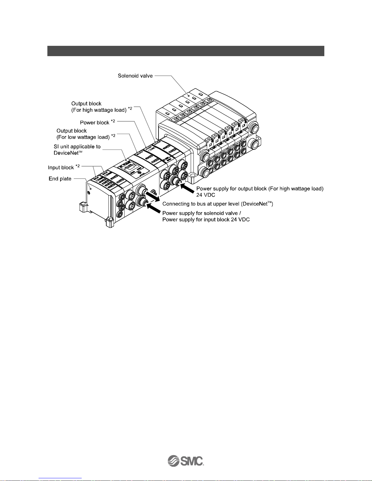
Product Summary
System configuration
This system connects input/output devices to DeviceNetTM with reduced wiring. DeviceNetTM communicates
with the input/output devices via the SI unit.
Input block and output block/valve manifolds of the EX9 series can be connected to 32 input points or 32
output points1maximum.
1: The maximum output points when the valve manifold or power block of the VQC series or S0700 series is used is 24 maximum
2: Refer to the operation manual EX-OME0002 for the input block specifications, and EX-OMH0005 for the output block and power
block specifications.

-9-
No.EX※※-OME0003-F
Model indication and How to Order
Summary of Product parts
No.
Element
Description
1
Communication connector
Sends or receives communication signals via DeviceNetTM line. 1
2
Power supply connector
Supplies power to the solenoid valve, output block, SI unit and input block. 1
3
Input block connector
Connects the input block
4
Output block connector
Connects the solenoid valve or output block etc.
5
Display window
Displays the status of the SI unit with LEDs. 2
6
Switch cover
Address and communication speed, etc. are set with the switches inside it. 2
7
Grounding terminal (FE)
Used for grounding.
1: Refer to “Wiring" on page 11 of this operation manual.
2: Refer to “Indication and settings” on page 17 of this operation manual.
-10-
No.EX※※-OME0003-F
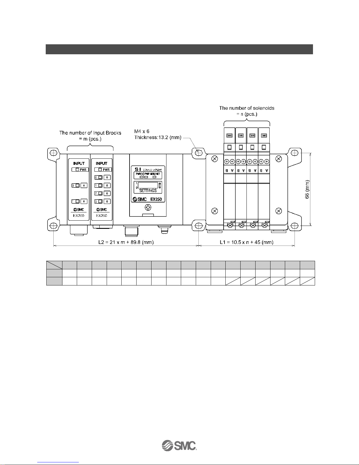
Mounting and Installation
■Installation
The SI unit does not have mounting holes, so it cannot be installed alone. Make sure to connect the valve
manifold. When an input block is not required, connect the end plate directly to the SI unit.
○Installation example
L
0
1
2
3
4
5
6
7
8
9
10
11
12
13
14
15
16
L1
45
55.5
66
76.5
87
97.5
108
118.5
129
139.5
150
160.5
171
181.5
192
202.5
213
L2
89.8
110.8
131.8
152.8
173.8
194.8
215.8
236.8
257.8
278.8
299.8
(mm)
: L1 shows the dimensions of the VQC1000 series solenoid valve.
Refer to the individual specifications for other solenoid valve series.
N_m
-11-
No.EX※※-OME0003-F
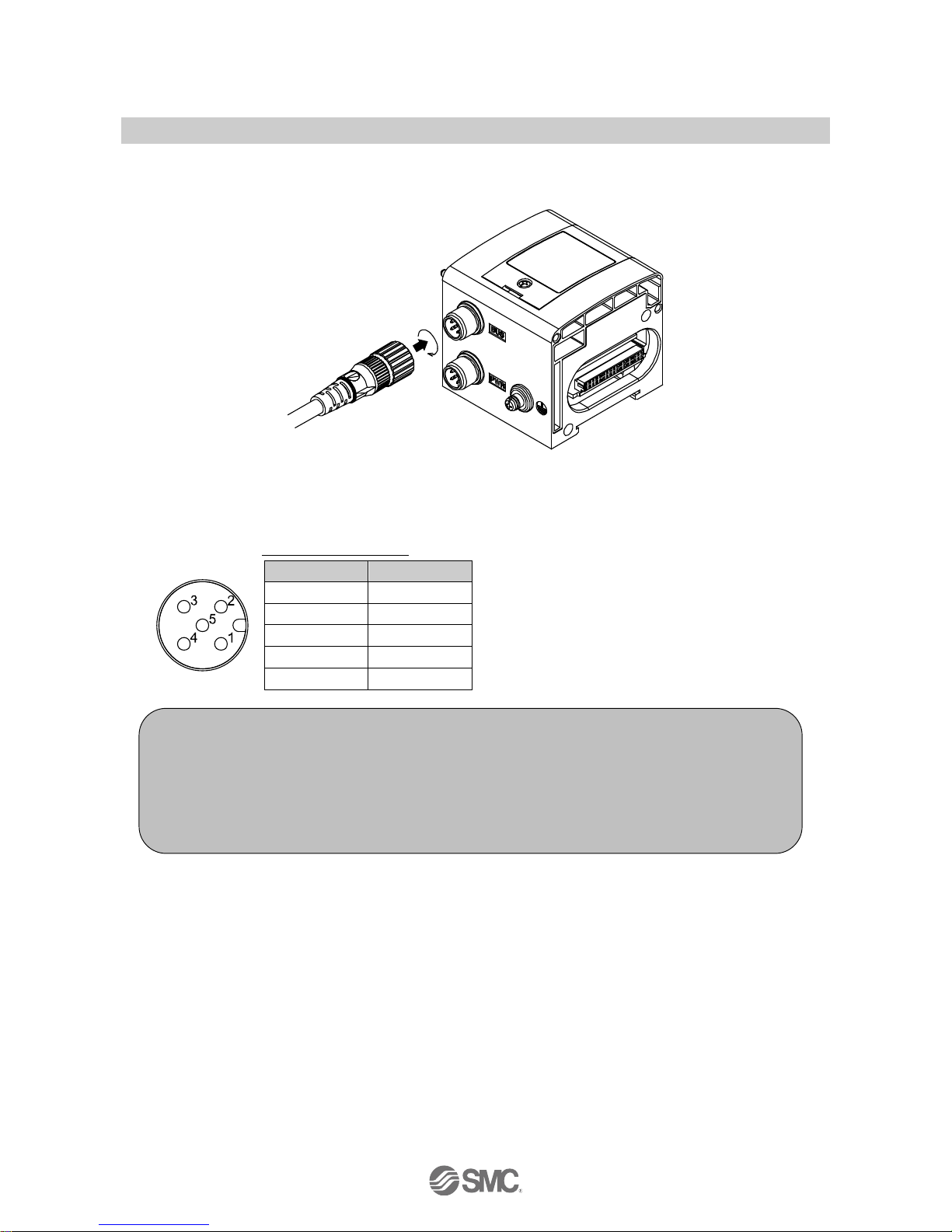
■Wiring
Connect the appropriate cable connector to the connector on the SI unit as shown below.
○Communication wiring
The DeviceNetTM communication connector specifications are shown below.
M12 5-pin plug A-code
Pin No.
Signal name
1
DRAIN
2
V+
3
V-
4
CAN_H
5
CAN_L
Note
Wiring should be carried out with the power supply turned off.
Do not route the communication cable near to high voltage cables such as a power cable or high
current electrical cable.
Make sure to connect terminal resistors to both ends of the DeviceNetTM main cable.
The drain wire should be connected to ground at one point only in the communication network.
Grounding should only be made at one point.
-12-
No.EX※※-OME0003-F
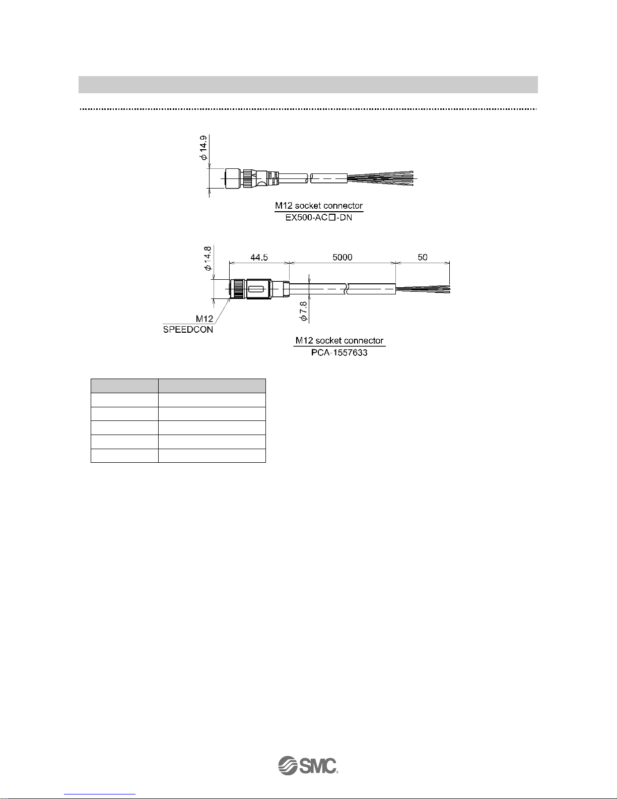
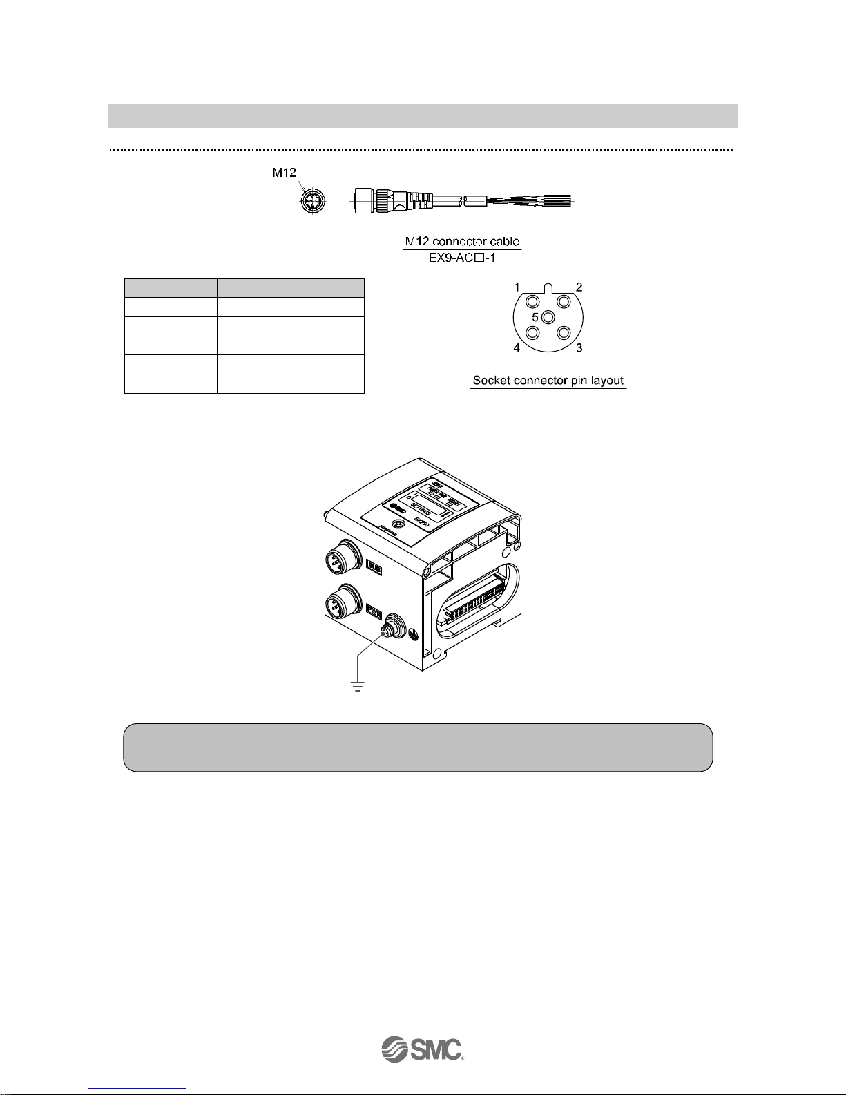
Pin Layout and Wiring of DeviceNetTM Communication Connector Cable
Connect the M12 connector cable (socket) to the communication connector.
Pin No.
Cable colour: Signal
1
DRAIN
2
Red: V+
3
Black: V-
4
White: CAN_H
5
Blue: CAN_L
-13-
No.EX※※-OME0003-F
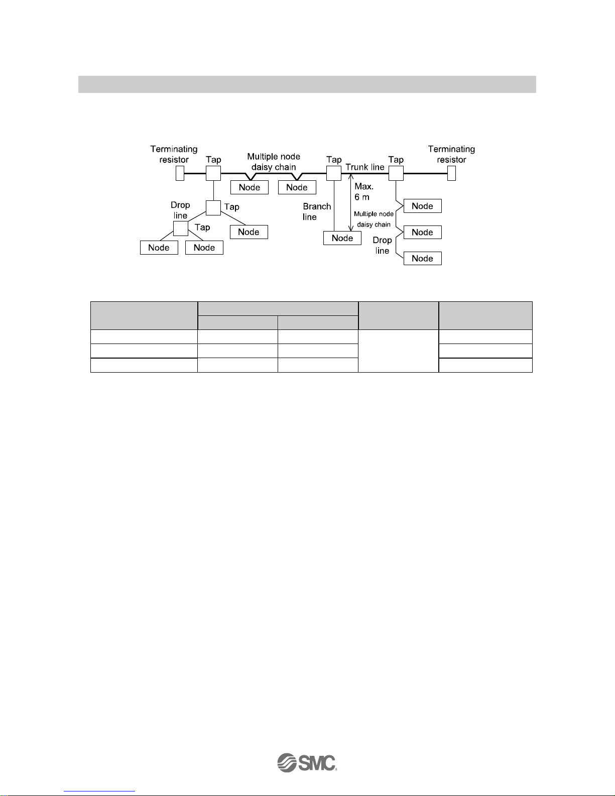
○DeviceNetTM Media Topology
A shielded twisted pair cable for DeviceNetTM should be used.
The maximum cable length depends on the communication speed and the cable type used.
<Communication speed [kbps] and max. bus cable length>
Communication speed
Maximum cable length for network
Drop line length
Cumulative Drop
Thick cable
Thin cable
500 kbps
100 m
100 m
6 m or less
39 m max
250 kbps
250 m
100 m
78 m max
125 kbps
500 m
100 m
156 m max
○Terminating resistors
DeviceNetTM requires a terminating resistor to be installed at each end of the trunk.
The resistor requirements are:
121 Ω
1% metal film
1/4 W
Terminating resistors should not be installed at the end of a drop line, only at the two ends of trunk line.

-14-
No.EX※※-OME0003-F
○Power supply wiring
Connect a power supply cable connector to the power supply connector on the SI unit.
Refer to "Safety Instructions" on page 2of this operation manual for the selection of the power supply.
○Power supply connector
(M12 5-pin B-code (reverse))
Pin No.
Description
Function
1
SV24 V
+24 V for solenoid valve
2
SV0 V
0 V for solenoid valve
3
SW24 V
+24 V for input block
4
SW0 V
0 V for input block
5
FE
Ground
-15-
No.EX※※-OME0003-F
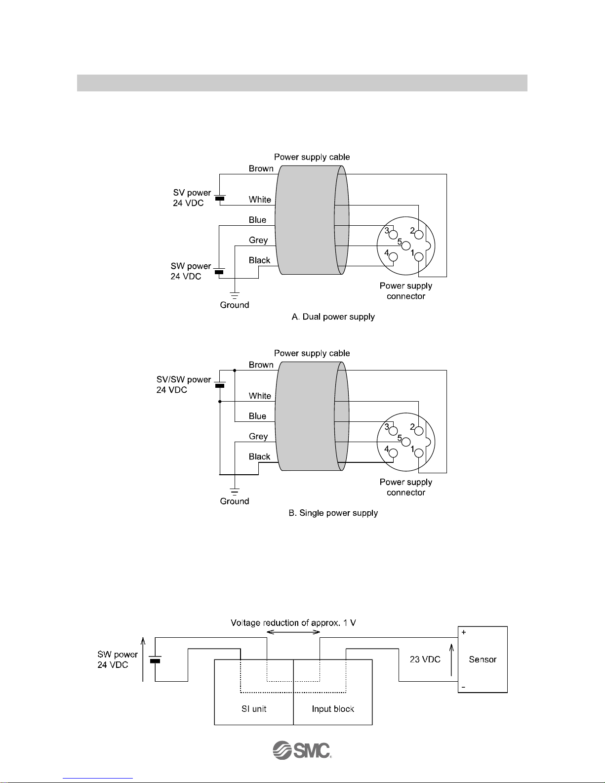
Pin Layout and Wiring of Power Supply Connector Cable
Pin No.
Cable color: Signal
1
Brown: SV24 V
2
White: SV0 V
3
Blue: SW24 V
4
Black: SW0 V
5
Grey: Ground
○FE connection
Note
Connect the ground terminal to the ground. Resistance to the ground should be 100 ohms or less.
-16-
No.EX※※-OME0003-F
Within the SI unit there are separate power supply lines for the solenoid valves (SV power supply) and for
the input block (SW power supply). Supply 24 V DC to each of them. Power can be supplied from a single
power supply or from separate power supplies.
It is not necessary to connect the SW power supply when not using an input block.
: When a single power supply is used, the voltage range of each power supply should be noted.
SW power is supplied to the sensor connected to the input block. There is a voltage drop of approximately 1
V maximum inside the SI unit when SW power is supplied. Select a sensor taking this voltage drop into
consideration. If 24 V must be supplied to the sensor, it is necessary to increase the SW power supply
voltage so that the input voltage of the sensor will be 24 V with the actual load. (Allowable SW power supply
range: 19.2 V to 28.8 V)
-17-
No.EX※※-OME0003-F
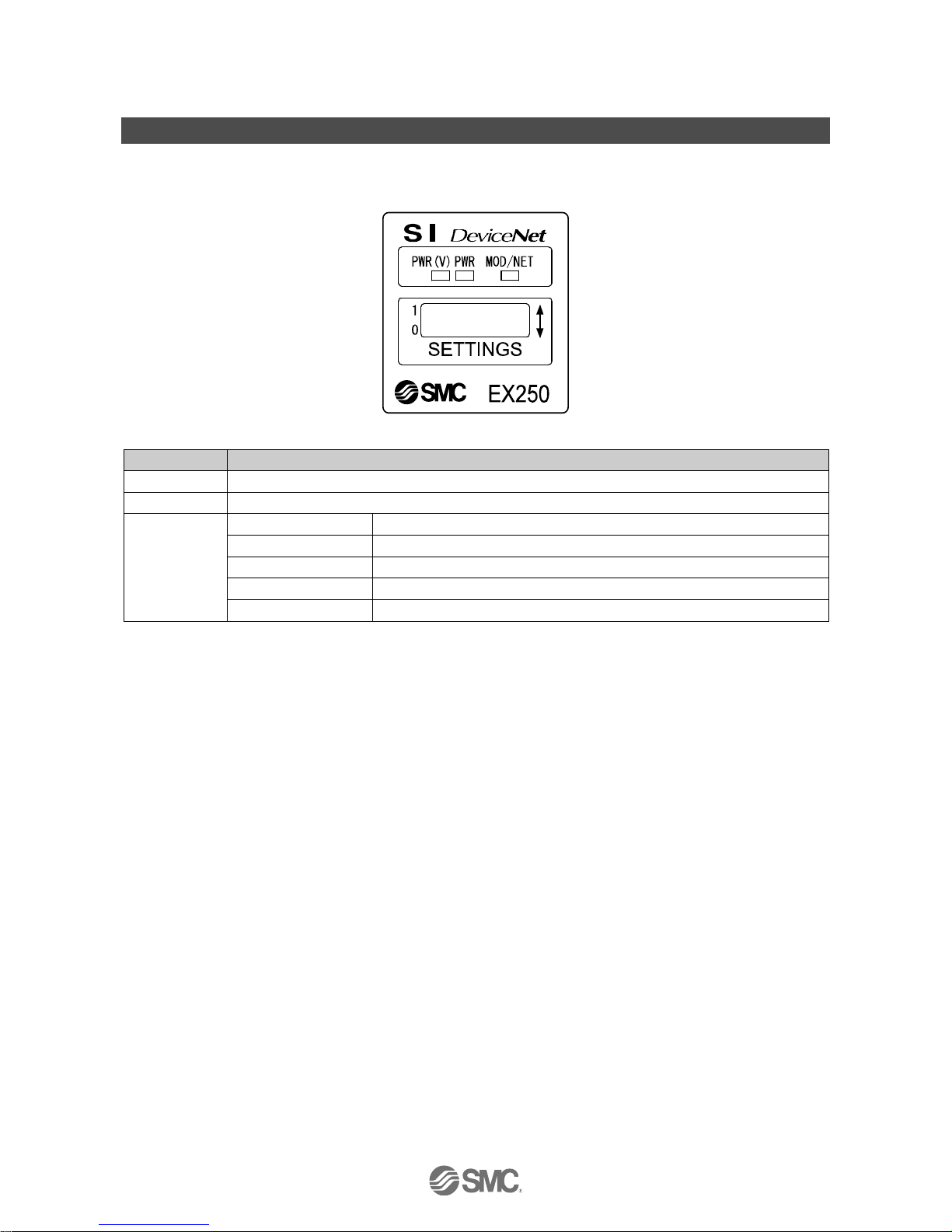
Indication and Settings
○Indication
EX250-SDN1/EX250-SDN1-X102
LED
Description
PWR (V)
Green LED is ON when power for solenoid valve is supplied.
PWR
Green LED is ON when power for DeviceNetTM communication is supplied.
MOD/NET
OFF
Power supply is off, on-line status or checking for MAC ID duplication.
Green LED is flashing
I/O connection stand-by (on-line status)
Green LED is ON
I/O connection established (on-line status)
Red LED is flashing
I/O connection time-out (minor communication error)
Red LED is ON
MAC ID duplication error or BUS OFF error (serious communication error)
: EX250-SDN1 disconnects the I/O connection when the solenoid valve power supply decreases or when the input block fuse is
detected to be broken (EX250-SDN1-X102 does not disconnect the I/O connection).

-18-
No.EX※※-OME0003-F
○Switch setting
Open the protective cover, and set the switches with a small flat blade screwdriver.
Address setting
Note
1. The power supply should be off while setting the switches.
2. Be sure to set the switches before use.
3. After setting the switches, close the switch cover and tighten the screw to the specified torque.
(Tightening torque: 0.6 Nm)
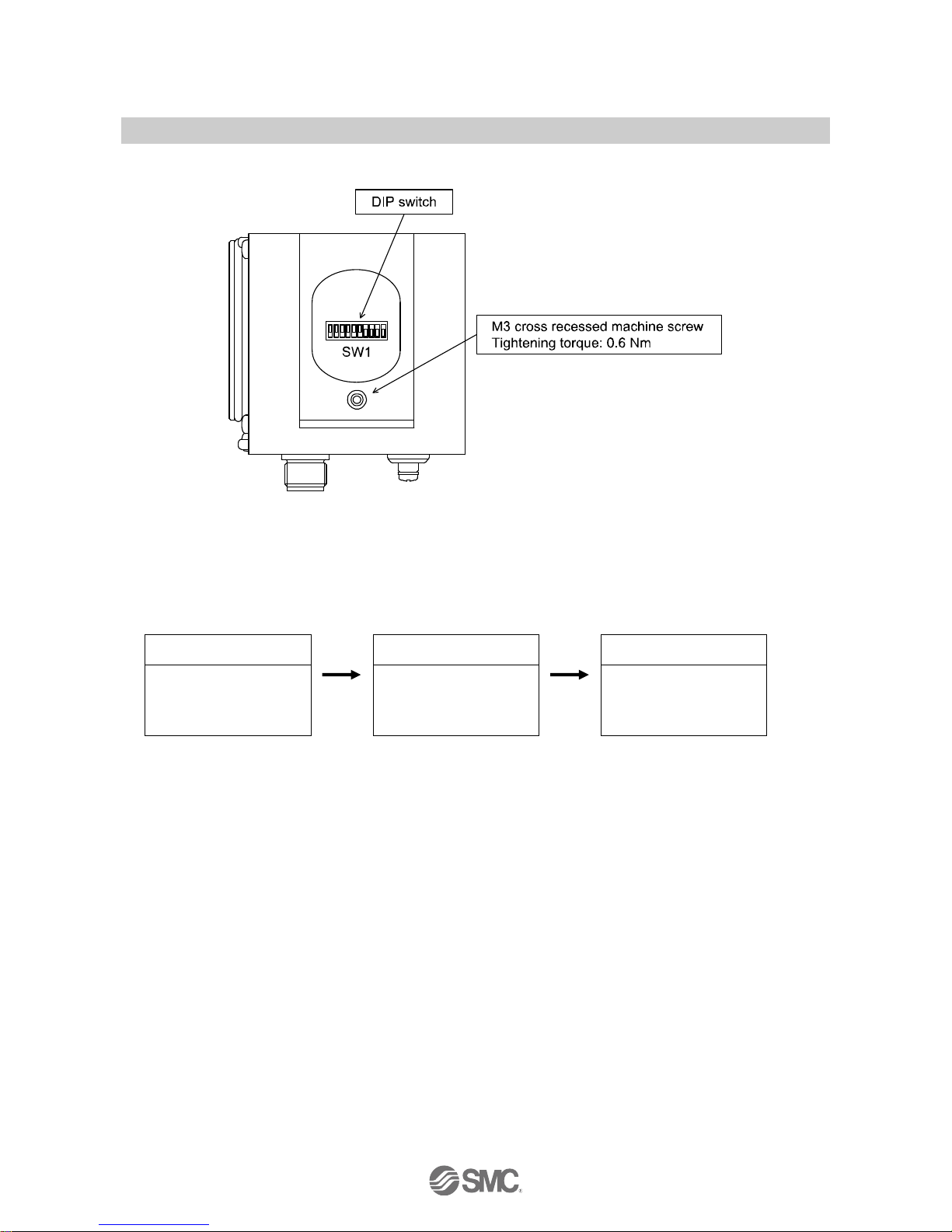
-19-
No.EX※※-OME0003-F
DIP switch position
Caution
The default settings are MAC ID 63 and communication speed 125 kbps (Hardware setting mode).
The MAC ID and communication speed set in SW setting mode are maintained even when the SI unit
power supply is turned off. When the power supply is applied in HW setting mode, the MAC ID and
communication speed set in SW mode are deleted, and the MAC ID and communication speed set by the
switches are memorized.
Software setting mode
Hardware setting mode
Software setting mode
MAC ID: 63
Communication speed:
125 kbps
MAC ID: 0
Communication speed:
500 kbps
MAC ID: 0
Communication speed:
500 kbps
The default output setting for when communication stops is 0 (all outputs to be cleared).
The output setting for when communication stops can be changed individually for each point via the
DeviceNetTM communication network. In this case, SW1-9 settings will become invalid.
This manual suits for next models
1
Table of contents
Other SMC Corporation Recording Equipment manuals


