4-Input / Output Interface
The four input/output interface unit can be configured
to provide any combination of up to four inputs and/or
outputs. An output of either normally open or
normally closed relay contacts can be used to control
a resistive or inductive load. An input can be
programmed as a fire, fault, supervisory or
confirmation input with configurable delay to filter
noise or spurious signals during switch transition.
Additionally the confirmation input can be configured
with an additional longer delay before an input is
accepted.
1-Output & 1/4-Input Interface
This interface unit can be used to control a resistive
or inductive load via a set of single pole change over
contacts. In addition there are 4 inputs for use to
monitor external equipment.
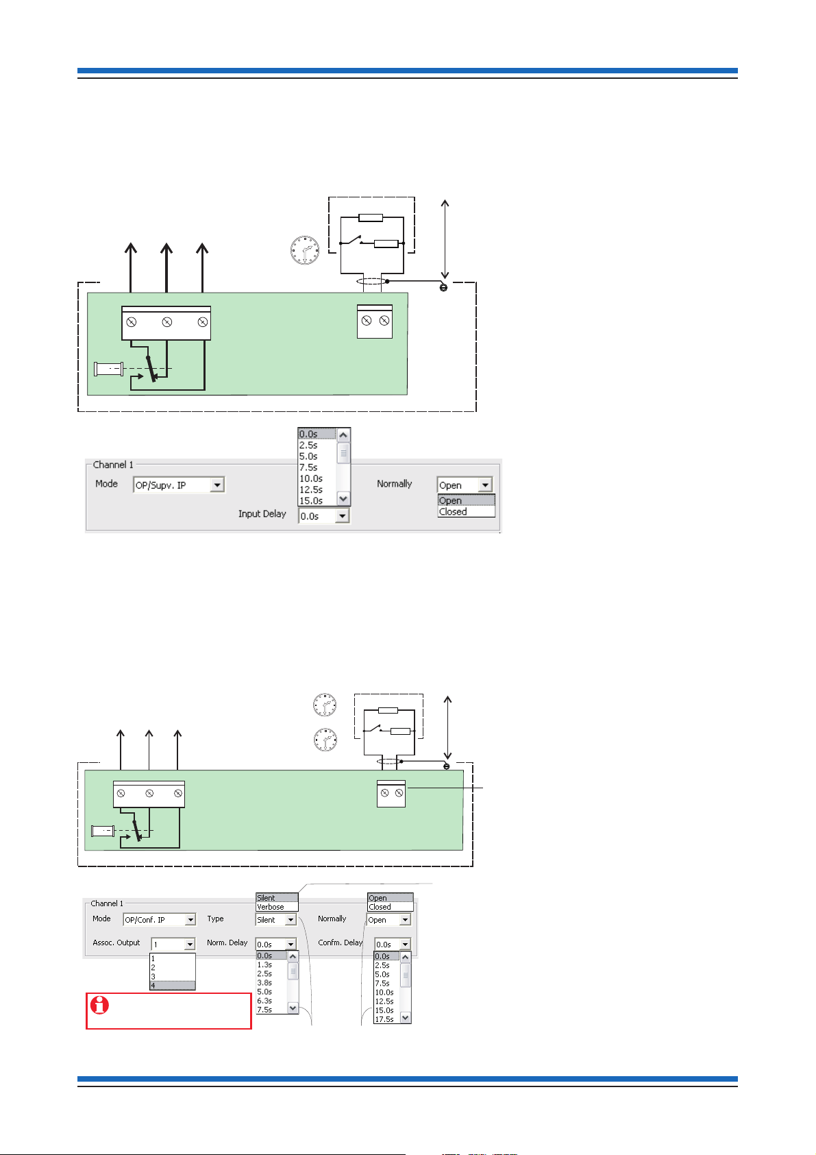
Confirmation Input / Output functionality
An input and an output of an interface unit can be
paired to operate in a confirmation mode. External
equipment can send an acknowledgement upon
receiving a signal from the interface unit, this is called
'confirmation input'. External equipment can also
receive an acknowledgement from the Interface unit
upon sending it a signal, this is called 'confirmation
output'.
Confirmation input
The confirmation input can be either a normally open
switch input or a normally closed switch input from
external equipment, such as a damper control unit.
A confirmation input generates a fault if a change of
state is not seen within the predefined period of a
specific output.
Unused Channels
Any unused channels must be configured as 'unused'
during the configuration stage using the
commissioning tool.
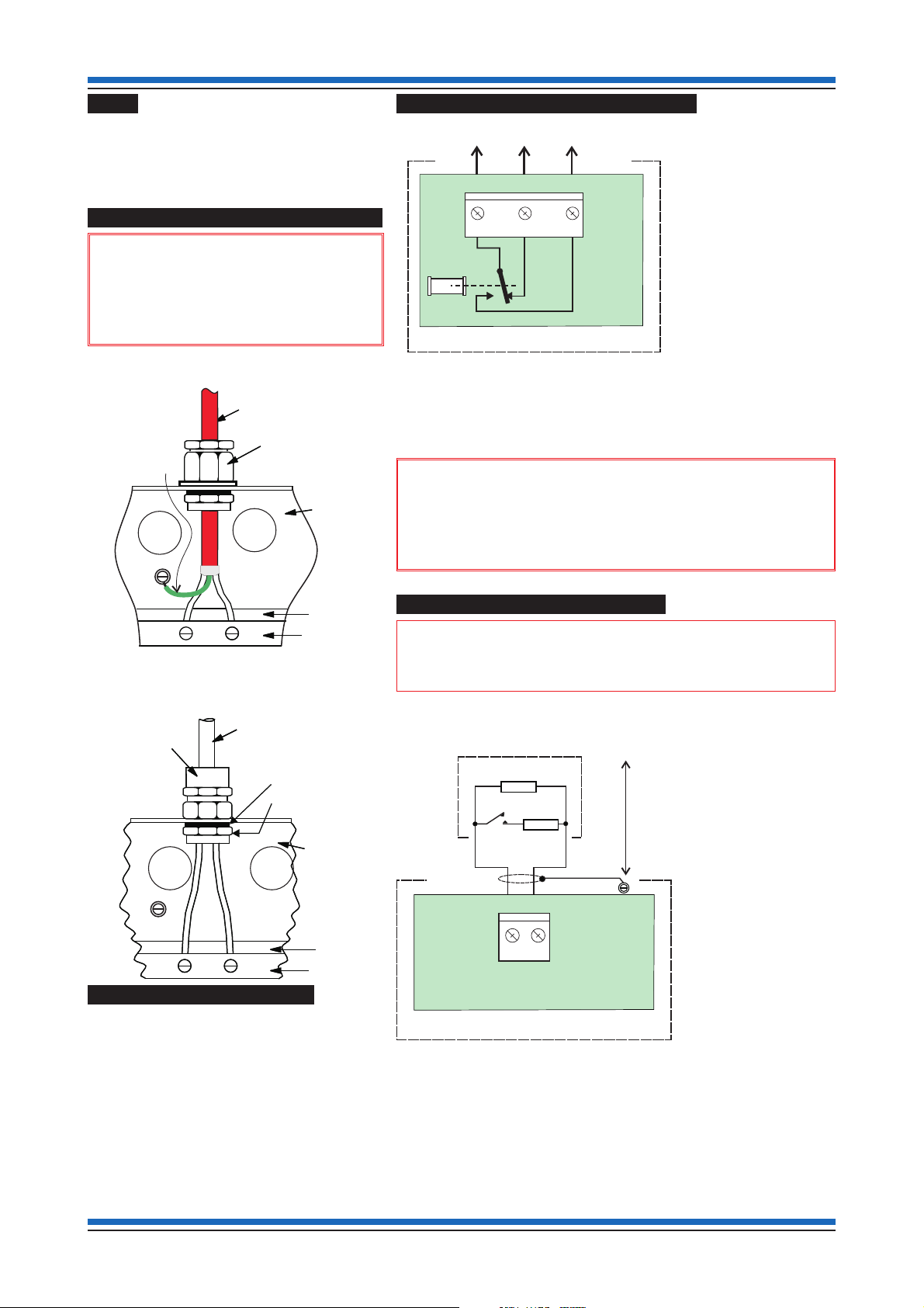
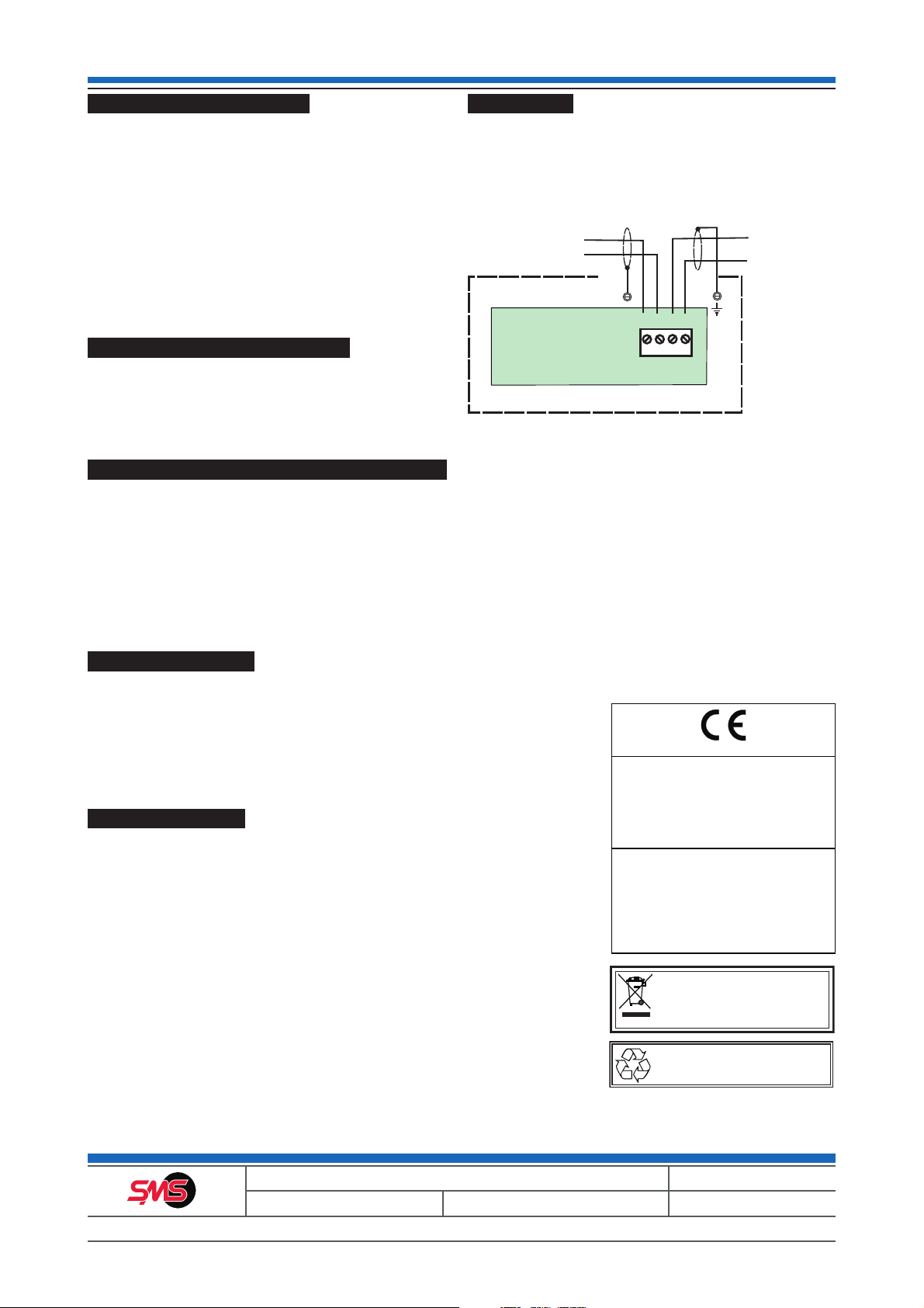
Loop wiring
The Mains switching interface unit must be wired to
the device loop circuit of the fire system. The loop
circuit can accommodate a number of Mains
switching interface units and on loop power up each
device is given a soft address.
Data and installation Mains Switching Interface
Gent by Honeywell reserves the right to revise this publication from time to time and make changes to the content hereof without
obligation to notify any person of such revisions of changes.
Hamilton Industrial Park, Waterside Road, Leicester LE5 1TN, UK Website: www.smsfire.co.uk
Telephone: +44 (0) 116 246 2100 Technical support: www.smstoolbox.co.uk Fax (UK): +44 (0)116 246 2016
4 4188-1002 issue 4_Part 1_09/13_Mains Switching I/F
At the end of their useful life, the packaging,
product and batteries should be disposed of
via a suitable recycling centre and in
accordance with national or local legislation.
Do not dispose of with your normal household waste.
Do not burn.
WEEE Directive:
At the end of their useful life, the packaging,
product and batteries should be
disposed of via a suitable recycling centre.
0V
L2
L1 0V
TB6
From Line 2
previous device
To Line 1
next device
Board
Mains Switching Interface Unit
SMS by Honeywell (Novar Systems Limited)
Manufactured by: Honeywell Life Safety Systems,
140 Waterside Road, Hamilton Industrial Park,
Leicester, LE5 1TN, United Kingdom
13
DoP Product No.
067-CPR-2013 SEN-INT-IOAC
067-CPR-2013 SEN-INT-4IOC
EN54-17: 2008/ AC 2007, EN54-18:2008 /AC 2007
SEN-INT-IOAC
SEN-INT-4IOC
Intended for use in fire detection and fire alarm systems
in and around buildings
Refer to 067-CPR-2013 for level or class of performance declared,
for details see website www.smsfire.co.uk
0359